Page is loading ...

www.ivalolighting.com
610.282.7472
Ivalo Finiré 4” LED Recessed Lighting
Installation Instructions
367-2202h 1 05.31.16
Important Notes
• IC fixtures must be used for installations containing insulating materials
and must be mounted away from heat producing elements (e.g., HVAC
ducts, hot water pipes, radiant heat floors, ovens). Non-IC fixtures
cannot be used in these types of applications.
• Non-IC fixtures are intended for free air applications. Do not confine
non-IC fixtures with insulation or building materials.
• Leads in junction box are ready for connection.
• Contractor is responsible for power connection.
• The mud ring shipped with trimless fixtures must be installed to ensure
desirable ceiling aesthetic.
•
Thermal protection device standard on non-IC housing fixtures (voltage
specific device: 120 V~ or 277 V~).
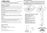
• 14 W and 17 W IC fixtures are 11.1 in (282 mm) long.
18W and 20 W IC fixtures are 17.3in (439 mm) long.
17 W, 18 W and 20 W Non-IC Fixtures are 11.1 in (282 mm) long.
See Dimensions.
•
Mounting brackets can be installed on either side of the fixture.
• Prior to fixture installation,
remove cable tie securing light module to the
fixture housing.
Fixture Installation
1. Turn off power.
WARNING: Shock Hazard.
Serious injury or death may occur.
Turn off power before servicing or installing. Wire according to local
and national codes. This product should be installed by a qualified
electrician.
2. Install fixture using the mounting bar based on mounting method
(Figure1). Mounting brackets can be installed on either side of the
fixture.
a. Insert mounting bar into mounting bar clamp.
b. Use mounting bar to secure to structure (notch allows for T-bar
installation). Secure wires to mounting bar
(if required).
c. Hammer barb into stud. Secure with mounting screws provided by
others.
3. To adjust mounting bar position (Figure 1 & 2):
a. Loosen both mounting bar clamp set screws
b. Adjust mounting bar to desired position
c. Tighten mounting bar clamp set screws
4.
Make power connections. See Circuit Diagrams for Dimming.
5. Cut out drywall to fit fixture aperture.
a. Round diameter: 4.7 in (119 mm)
b.
Square dimensions: 4.8 in x 4.8 in (122 mm x 122mm)
6.
For adjustable fixtures, aim fixture at desired location (Figure2).
a. Loosen rotation-locking thumb screws.
b. Aim fixture by rotating the module support bracket to the desired
position.
c. Tighten thumb screws.
Dimensions
IMPORTANT INFORMATION
Please Read Before Installing
Figure 1
Module
support
bracket
Rotation-locking
thumb screw
Mounting
bar clamp
set screw
Note: Enclosure and driver removed for visual clarity.
Figure 2
IC Housing
Non-IC Housing
Wire
Mounting
bar
Mounting
bar clamp
Barb
T-bar
notch
Leads and
ground
bundled
in junction
box.
Clip
11.1 in
(282 mm)
17.3 in
(439 mm)
9.5 in
(241 mm)
5.9 in
(150 mm)
11.1 in
(282 mm)
9.5 in
(241 mm)
4.2 in
(107 mm)

www.ivalolighting.com
610.282.7472
Ivalo Finiré 4” LED Recessed Lighting
Installation Instructions
367-2202h 2 05.31.16
Fixture Installation (continued)
7. For adjustable fixtures, adjust the tilt of the lamp module (Figure3).
a. Loosen tilt-adjust locking thumb screws.
b. Adjust aim of fixture by moving the module support bracket
along the track to one of the three stopping positions.
c. Tilt module support bracket to the desired angle.
d. Tighten thumb screws.
8. Install mud ring (Trimless only) (Figure 4).
Note: Trimless fixtures come with a screw hole template to assist
with mounting the mud ring.
a. Insert 4 screws (provided by others) into holes in mud ring and
screw into fixture. Screw length depends on ceiling thickness.
b. Use screws to level.
c. Ensure screws secure mud ring flush to drywall.
d. Apply plaster up to rim of mud ring.
e. Smooth plaster to blend with ceiling.
9. Install trim (Figure5).
a. Trimmed (round and square) and trimless (round):
i. Compress torsion springs at sides of trim
ii. Slide into trim brackets
iii. Allow springs to expand, drawing trim up into fixture
b. Trimless (square):
i. Push trim into opening until clips engage on sides
10. Restore Power.
Mud ring
Rim
Figure 4
Drywall
Plaster
Figure 5
Trim
bracket
Torsion
spring
Spring
clip
Torsion spring based trim
Spring clip based trim
Note: LED emitter
module removed
for visual clarity.
Tilt-adjust
locking
thumb
screw
Figure 3
Track
Stopping position
Module support
bracket

www.ivalolighting.com
610.282.7472
Ivalo Finiré 4” LED Recessed Lighting
Installation Instructions
367-2202h 3 05.31.16
Field Replace Components (optional)
WARNING: Risk of Fire or Electric Shock.
LED retrofit kit
installation requires knowledge of luminaire electrical systems.
If not qualified, do not attempt installation. Contact a qualified
electrician.
NOTICE: Property Damage.
To prevent damage or
abrasions, do not expose wiring to edges of sheet metal or
other sharp objects.
Note:
Do not make or alter any open holes in an enclosure of wiring or
electrical components during kit installation.
1. Changing Trim with Spring Clips (Figure6).
Note: This includes trimless (square) fixtures.
a. Insert a screwdriver between the rim of the trim and the
aperture opening.
b. Rotate the screwdriver to expose the lip of the trim.
c. Pull the trim down and remove from the fixture.
2. Changing Trim with Torsion Springs (Figure7).
Note: This includes trimmed (round and square) and trimless
(round) fixtures.
a. Holding the edge of the trim, pull it down until the torsion
springs engage.
b. Compress torsion springs and remove trim from the fixture.
3. Field Replace Reflector (Figure8).
a. Remove the trim. Refer to step 1 and 2 above.
b. Hold reflector by edges. Twist counter-clockwise to unlock from
the light module.
c. Carefully remove reflector.
d. Install new reflector. Twist clockwise to lock into light module.
4. Field Replace Light Module (Figure9).
a. Follow steps 1 and 2 to remove the trim and reflector.
b. Squeeze both light module clips and pull light module out of the
module support bracket.
c. Disconnect module from connector.
d. Connect new module to connector.
e. Secure new module into module support bracket. Make sure
all wiring is clear from the support bracket, light module, and
reflector.
5. Field Replace Driver.
Note: Refer to driver replacement guide.
a. Follow steps 1, 2, and 3 to remove the trim, reflector, and light
module.
b. Loosen the wing nuts on the driver support bracket (2or
3turns).
c. Remove the driver from the support bracket and pull out of the
aperture (Figure10). Disconnect the wires from the existing
driver.
d. Transfer the wing nuts to the studs on the new driver and
connect the wires to the new driver.
e. Insert new driver into aperture and install into the support
bracket.
f. Tighten wing nuts.
Figure 6
M4/6
flathead
screwdriver
Rim
Insert 1/2in
(13mm)
Figure 7
Figure 8
Figure 9
Figure 10
Torsion
spring
Reflector
Light module
LutronR LED driver
Note: Do not scratch the visible section of the trim.

www.ivalolighting.com
610.282.7472
Ivalo Finiré 4” LED Recessed Lighting
Installation Instructions
367-2202h 4 05.31.16
EcoSystem Control
Fixture
Line/Hot
120V~
2
Purple
E2 (Low-Voltage Data Link)
Purple
E1 (Low-Voltage Data Link)
Black
Forward Phase
Control
Hi-Lume 1%
2-Wire
Dimmable LED
Driver
(Mounted in
Grounded Fixture)
Fixture
Black
White
Neutral
Neutral
Circuit Diagrams for Dimming
2-Wire Forward Phase Control with Neutral (120 V~ only)
EcoSystem Digital Control (120/277 V~)
White
1
White
1
Ground
5
Ground
5
Line/Hot
120/277V~
2
Hi-lume 1%
EcoSystem Dimmable
LED Driver with
Soft-on Fade-to-Black
3
(Mounted in Grounded
Fixture)
To LEDs
4
To LEDs
4
1
Neutral may be optional for certain control types. See control specification submittal for specific wiring diagrams.
2
Refer to the specific Lutron control specifications for exact input voltage rating of the product.
3
40 W maximum rated drivers.
4
LED connectors are specific to LED / module type. Follow product guidelines on housing label for compatibility.
5
Ensure that both ground wires are connected in the junction box.
• Contact Fixture Customer Service for custom mounting options at fixtur[email protected]
• For a list of compatible controls and control ratings, visit www.lutron.com/finire or contact the LED
Control Center of Excellence at 1.877.DIM.LED8 or leds@lutron.com

Ivalo Finiré 4” LED Recessed Lighting
Installation Instructions
IVALO COLLECTION
367-2202h 5 04.16.19
) Lutron, Lutron, EcoSystem, IVALO, IVALO Lighting
(registered in the U.S. only), Hi-lume, Finiré Lutron Ivalo
Collection, and Soft-on Fade-to-Black are trademarks or
registered trademarks of Lutron Electronics Co., Inc. in the
US and/or other countries.
©2012-2019 Lutron Electronics Co., Inc.
Lutron Electronics Co., Inc.
7200 Suter Road, Coopersburg, PA 18036
Telephone 610.282.7472 Fax 610.282.7600
For limited 10-year warranty details, see
www.lutron.com/TechnicalDocumentLibrary/3683454.pdf
FCC Statements
LED Type “35” with EcoSystem Driver Options – Class A
• NOTE: This equipment has been tested and found to comply with the limits for a Class A digital device,
pursuant to part 15 of the FCC Rules. These limits are designed to provide reasonable protection against
harmful interference when the equipment is operated in a commercial environment. This equipment generates,
uses, and can radiate radio frequency energy and, if not installed and used in accordance with the instruction
manual, may cause harmful interference to radio communications. Operation of this equipment in a residential
area is likely to cause harmful interference in which case the user will be required to correct the interference at
his own expense.
• CAN ICES-005 (A) / NMB-005 (A)
All Other Models – Class B
This device complies with part 15 of the FCC Rules. Operation is subject to the following two conditions:
(1) This device may not cause interference, and
(2) This device must accept any interference, including interference that may cause undesired operation.
Modifications not expressly approved by Lutron Electronics Co., Inc. could void the user’s authority to operate
this equipment.
NOTE: This equipment has been tested and found to comply with the limits for a Class B digital device,
pursuant to part 15 of the FCC Rules. These limits are designed to provide reasonable protection against
harmful interference in a residential installation. This equipment generates, uses and can radiate radio
frequency energy and, if not installed and used in accordance with the instructions, may cause harmful
interference to radio communications. However, there is no guarantee that interference will not occur in a
particular installation. If this equipment does cause harmful interference to radio or television reception,
which can be determined by turning the equipment off and on, the user is encouraged to try to correct the
interference by one or more of the following measures:
• Reorient or relocate the receiving antenna
• Increase the separation between the equipment and receiver
• Connect the equipment into an outlet on a circuit different from that to which the receiver is connected
• Consult the dealer or an experienced radio/TV technician for help
CAN ICES-005 (B) / NMB-005 (B)
/