Page is loading ...

Need Help? Please visit the Hi-lume Premier 0.1% page at www.lutron.com or
call Lutron Customer Assistance at 1.844.LUTRON1 (1.844.588.7661)
Hi-lume Premier 0.1% EcoSystem / 3-Wire Voltage LED Driver
Installation
L3D0-96W24V-U UL® Listed Driver
Output: 2–96 W 24 V- Input: 120–277 V~ 50 / 60 Hz, Max 110 W
Important Notes: Please read before installing.
• For installation by a qualified electrician in accordance with all local and national electrical codes.
• Use copper conductors only.
• For indoor use only.
• For 277 V~ applications, a suitable barrier may be required between the non-Class 2 and Class 2
wiring, per local and national electrical wiring codes. For your convenience, the driver includes an
optional barrier.
• Check to see that the driver type and rating are suitable for the application.
• DO NOT install if product has any visible damage.
• If moisture or condensation is evident, allow the product to dry completely before installation.
• Operate between 32 °F (0 °C) and 104 °F (40 °C) ambient.
• 0% to 90% humidity, non-condensing.
• Four 8-32 × 3/8 in (9.5 mm), serrated lid screws provided.
• For best practices, please refer to Application Note #591 (P/N 048591) at www.lutron.com
* Driver and control must be grounded in accordance with local and national electrical codes.
Lutron Electronics Co., Inc. | 7200 Suter Road | Coopersburg PA, 18036-1299
English
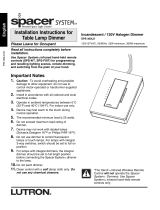
Mounting
(mount as shown on the right)
1. Remove top cover to access multi-sided mounting key holes.
2. Mount driver per the options shown to the right.
Notes
• Minimum of 3 in (76 mm) required between any two LED drivers.
• Install in accordance with all national and local electrical codes.
• Mount driver in a position where it can be easily located and accessed if service
or troubleshooting is necessary.
• Any other mounting configuration will require additional mechanical support.
Improper installation may result in hazards to personnel or property.
Wiring
(wire as shown below)
!
WARNING: Shock Hazard. May result in serious injury or death.
Turn off power at circuit breaker before installing the unit.
1. Remove top cover to access the terminal blocks.
2. Open necessary knockouts to pass wires into the wiring compartment.
3. Connect the necessary wires according to the illustration below. For E1 / E2
wiring, please refer to Application Note #142. Terminals accept 12AWG to
20AWG (0.50 mm
2
to 2.5 mm
2
).
4. Optional - An AC line cord may be used for a 120 V~ application. The line
cord must include a grounded plug to be a valid installation as shown to the right.
277 V~ applications cannot use a line cord, they must be hard-wired.
5. Optional - Add barrier between non-Class 2 and Class 2 wires (e.g.,EcoSystem
wiring shown below has E1 / E2 as Class 2, therefore barrier is placed between
input and control terminal block).
6. Rotate Field Adjustment Knob to full counter-clockwise position.
7. Ensure compatible dimmer and load are installed and restore power to the circuit.
See reverse side for Compatible Controls.
041597 Rev. A
2/2017
Required Components For each system, ensure that you have:
At least one compatible
LED Load (light engine)
3
1
See list of compatible controls on the reverse side.
2
Please refer to the control installation sheet for wiring instructions.
3
Refer to LED load manufacturer instructions for proper installation practices.
Load ratings must match driver output ratings.
At least one Hi-lume
Premier 0.1% Driver
One Compatible
Lutron Control
1,2
lutron.com
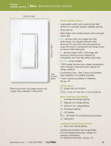
3-Wire Wiring Diagram
Hi-lume
Premier
0.1%
Driver
Switched Hot (L)
Neutral (N)
Neutral
Line /
Hot
+ LED
– LED
LED
Light
Engine
Dimmed Hot (DH)
Ground* (D)
Ground*
Ground*
Lutron
3-Wire
Dimmer
EcoSystem Wiring Diagram
Hi-lume
Premier
0.1%
Driver
E1
E2
Line / Hot (L)
Neutral (N) Neutral
Line / Hot
+ LED
– LED
LED Light
Engine
Ground* (D)
Ground*
To EcoSystem
Digital Link
3-Wire Controls
Switched Hot (L)
From Line/Control
120 – 277 V~
50 / 60 Hz
To LED Load
Neutral (N)
Dimmed Hot (DH)
Ground* (D)
+ LED
– LED
EcoSystem Controls
E1
E2
Line / Hot (L)
From Line/Control
120 – 277 V~
50 / 60 Hz
To LED Load
To EcoSystem Digital Link
Neutral (N)
Ground* (D)
+ LED
– LED
A barrier (included) in the wiring compartment separates non-Class2
and Class2 wires. Barrier can be placed between control and output
terminals (Option1) or between input and control terminals (Option 2).
Option 1
Option 3
Option 2
Mounting Surface
Barrier
Output
Control
Input
Barrier
Output
Control
Input
Line Cord

Warranty
For warranty information, please visit:
www.lutron.com/DriverWarranty
)Lutron, Lutron, Ariadni, Diva, GRAFIK Eye, Hi-lume, HomeWorks,
Maestro, Maestro Wireless, Nova, Nova T*, PowPak, Quantum,
RadioRA, EcoSystem, and Skylark are trademarks of Lutron
Electronics Co., Inc. registered in the U.S. and other countries.
Energi Savr Node and Soft-on, Fade-to-Black are trademarks of
Lutron Electronics Co., Inc.
©2015 – 2017 Lutron Electronics Co., Inc.
L3D0-96W24V-U Troubleshooting
Problem Possible Solution
LED does not illuminate
at high-end
• Verify that the system is wired correctly according to wiring diagram and
powered.
•
Verify that the LED load is wired correctly; +LED to positive, -LED to negative.
• Verify that the LED load is for “constant-voltage” applications with PWM
dimming.
• Verify that the LED load is compatible with the specified voltage output
of the driver.
• Lutron drivers are not for use with MR16 LED lamps.
LED does not illuminate
at low-end
• Verify that the low-end trim on the control is set properly.
• Turn Field Adjustment Knob clockwise until desired low-end operation is
obtained.
LED does not dim • Verify that Switched Hot and Dimmed Hot are connected to the proper
terminals for 3-wire control.
• Verify EcoSystem control wiring (E1 and E2) is wired according to the
instructions for digital control.
LED turns on / off
abruptly without Soft-on,
Fade-to-Black feature
• Turn Field Adjustment Knob counter-clockwise until desired low-end
operation is obtained.
• 3-wire control does not have Soft-on, Fade-to-Black dimming
technology.
LED is flashing,
flickering, dropping out,
or has poor dimming
performance
• Verify that a compatible dimmer is being used to control the driver.
• Verify that the input voltage is within the rated limits.
• Verify that Switched Hot and Dimmed Hot are connected to the proper
terminals.
• Verify that the LED load is for “constant-voltage” with PWM dimming
applications.
• Verify that the length of wires between driver and LED does not exceed
specification.
• Verify that the rated voltage is present at the driver.
• Certain types of LED loads may be incompatible.* Verify that the LED
load is within the specified wattage range of 2 W to 96 W.
• Lutron drivers are not for use with MR16 LED lamps.
LED is flashing slowly
(6to 8 second interval)
• Verify that the LED load does not exceed the maximum specified power
rating of the driver (96 W).
• Verify that the LED load matches the specified voltage output of the driver.
• Verify that the length of wire between driver and LED does not exceed
specification.
• Certain types of LED loads may be incompatible.
*
LED output appears
dim at high-end
• Verify that rated line voltage is present at the terminal.
• Verify that the driver is operating in an environment within its ambient
temperature rating.
• Verify that the driver is not located adjacent to other heat producing
devices. Verify that space between drivers is greater than 3 in (76 mm).
• Verify that the maximum lead length is not exceeded per Lutron
recommendation.
• Verify that the LED load is installed per manufacturer’s instructions.
• Verify that the LED load is compatible with the specified voltage output
of the driver.
Not all LED strips/
fixtures illuminate
• Verify that multiple LEDs connected to a single driver are properly wired.
• Verify that the LED load is installed per manufacturer’s instructions.
Not all LEDs on the
same strip are evenly lit
• Verify that the length of wire between the driver and LED does not
exceed specifications.
• Verify that the LED load is for “constant-voltage” with PWM dimming
applications.
• Verify that the LED load is installed per manufacturer’s instructions.
LED is brighter / hotter
than expected
• Verify that the LED load is compatible with the specified voltage output
of the driver.
* Certain constant-voltage loads may have added capacitance. Contact the Lutron LED Center of Excellence at 1.877.346.5338 or
LEDs@lutron.com for more information about these loads.
Hi-lume Premier 0.1% EcoSystem / 3-wire Voltage LED Driver
Compatible Controls
Compatible Controls
• 3-Wire Controls
• EcoSystem Controls
Consult individual component installation
guides for more details.
Driver Leads
Maximum wire length between LED driver and
start of the light engine:
Wire Gauge* Maximum Lead Length
24 AWG (0.20 mm
2
)* 6 ft (1.8 m)
22 AWG (0.75 mm
2
)* 10 ft (3.0 m)
20 AWG (0.50 mm
2
) 15 ft (4.5 m)
18 AWG (0.75 mm
2
) 25 ft (7.62 m)
16 AWG (1.0 mm
2
) 40 ft (12.2 m)
14 AWG (1.5 mm
2
) 60 ft (18.3 m)
12 AWG (2.5 mm
2
) 100 ft (30.5 m)
10 AWG (4.0 mm
2
)* 150 ft (45.7 m)
* To use wire gauges larger or smaller than terminal
blocks’ rated gauge of 20 AWG to 12 AWG (0.50 mm
2
to 2.50 mm
2
), connect 12 in (30 cm) or less of rated
wire from terminal and connect with larger or smaller
wire.
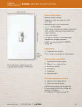
Field Adjustment Knob
Adjusting knob on the outside of the
enclosure changes the minimum
light level that is reached during
normal operation. This feature
enables the user to address light
output mismatch between two or
more drivers at low-end dim level.
Driver is initially defaulted to the
minimum light output when at
low-end. For more information,
please refer to Application Note
#591 (P/N 048591) at www.lutron.
com
1. Ensure knobs on all drivers are in the full
counter-clockwise position.
2. Set control to get lowest light level.
3. Turn knob clockwise to adjust light output to
match the brightest driver.
4. Repeat steps 2-3 for the remaining drivers.
Compatible Controls
For assistance in selecting controls, contact our LED Center of Excellence.
3-Wire Controls (without Soft-on, Fade-to-Black dimming technology)
Product
Model Number Drivers per Control**
Load Selection
Type
Low-end
trim setting
†
120 V~ 277 V~ 120 V~ 277 V~
Nova T*
NTF-10- NTF-10-277- 1 – 16 1 – 19 — —
NTF-103P- NTF-103P-277- 1 – 8 1 – 14 — —
Nova
NF-10- NF-10-277- 1 – 16 1 – 19 — —
NF-103P- NF-103P-277- 1 – 8 1 – 14 — —
Skylark
SF-10P- SF-12P-277- 1 – 8 1 – 14 — —
SF-103P- SF-12P-277-3- 1 – 8 1 – 14 — —
Diva
DVF-103P- DVF-103P-277- 1 – 8 1 – 14 — —
DVSCF-103P- DVSCF-103P-277- 1 – 8 1 – 14 — —
Ariadni AYF-103P- AYF-103P-277- 1 – 8 1 – 14 — —
Maestro
MAF-6AM- MAF-6AM-277- 1 – 6 1 – 14 — —
MSCF-6AM- MSCF-6AM-277- 1 – 6 1 – 14 — —
Maestro Wireless MRF2-F6AN-DV- 1 – 6 1 – 14 — —
RadioRA 2 RRD-F6AN-DV- 1 – 6 1 – 14
Dual voltage 3-wire
dimmer
21%
†
HomeWorks QS HQRD-F6AN-DV- 1 – 6 1 – 14
Fluorescent 3-wire
LED 3-wire
21%
†
Interface
PHPM-3F-120- — 1 – 16 — — —
PHPM-3F-DV- 1 – 16 1 – 38 — —
BCI-0-10 1 – 16 1 – 38 — —
GP Dimming Panel Various 1 – 16 1 – 38 2 – 1 —
EcoSystem Controls (with Soft-on, Fade-to-Black dimming technology)
Product
Model Number
Recommended
System Version
r
Drivers per Control
120 – 277 V~ 120 V~ 277 V~
PowPak Dimming Module
with EcoSystem
RMJ-ECO32-DV-B,
URMJ-ECO32-DVB
5.9 or higher 32 per EcoSystem link
PowPak Wireless Fixture
Control with EcoSystem
‡
FCJ-ECO
FCJS-ECO
0796554 or higher 3 per EcoSystem link
Energi Savr Node with
EcoSystem
QSN-1ECO-S, QSN-2ECO-S,
QSN-2ECO-PS120,
UQSN-1ECO-S, UQSN-2ECO-S
9.027 or higher 64 per EcoSystem link
GRAFIK Eye QS with
EcoSystem
QSGRJ-_E,
QSGR-_E
— 9.009 or higher 64 per EcoSystem link
Quantum Light
Management Hub
QP2-_P_C — 3.2 or higher
§
64 per EcoSystem link
HomeWorks QS with
EcoSystem
LQSE-2ECO-D,
QSGRJ-_E,
QSGR-_E,
— 10 or higher* 64 per EcoSystem link
NOTE: For information about Legacy product use in existing control applications, contact LEDs@lutron.com
** No derating required in multigang applications provided that the driver count does not exceed the quantity listed.
†
21% trim allows for 0.1% low-end level but might result in dead travel for 1% – 4% on user interface. 22% trim can be used to avoid dead travel but
may result in >0.1% low-end level.
‡
All devices connected to one PowPak wireless fixture controller will be controlled together. Devices will dim to the same level as the result of a
control command. Control will need to have low-end level reprogrammed to dim to 0.1% output. For more details, refer to Application Note #556 at
www.lutron.com.
§
Version 3.1 (or higher) is required to dim lower than 1%.
* Version 7.0 (or higher) is required to dim lower than 1%.
r
For lower system versions, please visit www.lutron.com/LEDsystemcheck to check if your system requires changes.
/