INSTALLATION INSTRUCTIONS
For item#4635-106 (New. 12/11/2017)
READ AND SAVE THESE INSTRUCTIONS
WARNING! SHUT POWER OFF AT FUSE OR CIRCUIT BREAKER.
AVERTISSEMENT! COUPER LE COURANT AU NIVEAU DES FUSIBLES OU DU DISJONCTEUR.
Fig. 1
Fig. 2
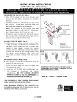
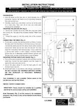
PREPARING FOR INSTALLATION (Fig. 1)
1. Shut off the power at the fuse box or circuit breaker box
and remove the old fixture from the ceiling, including
the mounting hardware.
2. Carefully unpack your new fixture and lay out all the
parts in a clear area. Take care not to lose any small
parts necessary for installation.
3. Thread the nipple (E) into the crossbar (C) until snug.
Note: The length of the nipple (E) into the crossbar (C)
may be adjusted if necessary.
4. Use the lock washer (B) and hex nut (A) to secure the
nipple (E) into the crossbar (C).
5. Take this crossbar (C) assembly and mount it to ceiling
outlet box with mounting screws (D) (Size:
#8-32N*L0.5”). The side of crossbar marked with
“GND” must face out.
6. Secure metal tube (T) into nipple (I).
7. Determine the desired hanging height and thread rods
(F1, F2 and F3) to the nipple of the metal tube (T).
Then attach loop (H1) by screwing in to rod (F1). Note:
remove the nipple if installing with one 6” rod only.
8. Attach the quick link (G) to loop (H1) and loop (H2) on
the canopy (F), carefully feed the wire over loop (H1),
quick link (G) and loop (H2).
9. The support cable is provided to support the weight of
the fixture while wiring. Align the fixture to Crossbar (C)
and attach hook (Q) on the end of support cable (P)
into a slot located on Crossbar (C). Carefully allow the
support cable (P) to support the weight of the fixture
while wiring.
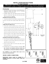
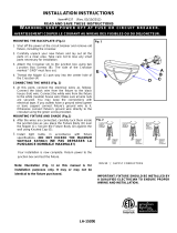
CONNECTING THE WIRES (Fig.2)
10. At this point, connect the electrical wires as shown in
figure 2, making sure that all wire connectors are
secured. If your outlet has a ground wire (green or bare
copper), connect the fixture’s ground wire to it.
Otherwise, connect the fixture’s ground wire directly to
the crossbar using the green screw provided.
11. Tuck the wire connectors neatly into the ceiling
Junction Box and then raise the canopy all the way to
the ceiling.
12. Place the canopy (F) over the nipple (E), and secure
the canopy (F) against the ceiling using knurled cap
(S).
13. Secure metal tube (N) into the fixture body (O).
14. Place the candle covers (L) over the sockets (M).
15. Install the bulb(s) (K) (included) in accordance with the
fixture’s specification. (DO NOT EXCEED THE
MAXIMUM WATTAGE RATING!) (NE PAS
DEPASSER LA PUISSANCE NOMINALE
MAXIMALE!).
16. Put the glass shade (J) over the socket (M) and turn to
secure it to the fixture.
Your installation is now complete. Return power to the
outlet box and test the fixture.
Note: Illustration (Fig. 1) on this manual is for
installation purposes only. It may or may not be
identical to the fixture purchased.
LA-2885E
FIXTURE
WIRES
Black or
Smooth
H
O
U
S
E
WIRES
Black
(Hot)
FIXTURE
WIRES
White or
Ribbed
H
O
U
S
E
WIRES
White
(Neutral)
FIXTURE
WIRES
Bare
Copper
(Ground)
H
O
U
S
E
WIRES
Green
(Ground)
Set# A-010
- Crossbar
- Ground screw
- Mounting screw*2
Rod# W30-1-84*2(F1)
W30-1-84*4(F2)
W30-H-84*2(F3)
Candle Cove
r
#CCV24052P-84
F3
C
D
F
E
A
G
H1
S
F2
F1
T
I
M
K
J
N
B
Q
L
H2
O
P
/