Page is loading ...

A
Smart Locker
Installation Instructions
Scale 1 : 1
0 11/2
1/4 1/4
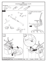
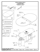
Tools Required
1/8” DRILL
5_41729 1 of 9 6100-0257 1Rev:Part No:Page:E.C.O. No:
CUSTOMER SERVICE PHONE: 1-800-426-8562
#2
#10-16 x 1-1/4"" Pan Head Screw
(S-42)
S-42
S-42
S-42
S-42
B
1

A
C
2 of 9 1Rev:Part No:Page:E.C.O. No:
CUSTOMER SERVICE PHONE: 1-800-426-8562
6100-0257
#10-16 x 1-1/4"" Pan Head Screw
(S-42)
2
S-42
S-42
B
5_41729

D
C
3 of 9 1Rev:Part No:Page:E.C.O. No:
CUSTOMER SERVICE PHONE: 1-800-426-8562
6100-0257
#10-16 x 1-1/4"" Pan Head Screw
(S-42)
S-42
D
A
A
3
FLUSH
5_41729

D
4 of 9 1Rev:Part No:Page:E.C.O. No:
CUSTOMER SERVICE PHONE: 1-800-426-8562
6100-0257
#10-16 x 1-1/4"" Pan Head Screw
(S-42)
E
S-42
S-42
4
5_41729

5 of 9 1Rev:Part No:Page:E.C.O. No:
CUSTOMER SERVICE PHONE: 1-800-426-8562
6100-0257
E
F
G
G
F
F
OR
11
2
22
1
S-42
S-42
S-42
S-42
INSTALL TOP FIRST
INSTALL
SIDES LAST
INSTALL
SIDES LAST
INSTALL
SIDES FIRST
INSTALL
SIDES FIRST
INSTALL
TOP LAST
5
NOTE: Trim is installed in
the order that depends on
the nished appearance.
5_41729

6 of 9 1Rev:Part No:Page:E.C.O. No:
CUSTOMER SERVICE PHONE: 1-800-426-8562
6100-0257
F2
S-42
S-42
6
5_41729

7 of 9 1Rev:Part No:Page:E.C.O. No:
CUSTOMER SERVICE PHONE: 1-800-426-8562
6100-0257
H
7
8
NOTE: Electronic Lock Representative
will determine lock location.
NOTE: See template on last page
when location lock ange (J).
NOTE: Hardware is provided
by the user.
NOTE: Hardware is provided
by the user.
J
K
L
5_41729

8 of 9 1Rev:Part No:Page:E.C.O. No:
CUSTOMER SERVICE PHONE: 1-800-426-8562
G
G
DOOR HINGE ADJUSTMENTDOOR INSTALLATION/REMOVAL
2
1
1
2
3
1
2
3
4
3
CK-3 CK-3
HW-SERIES
X
HW-SERIES
Install lock plug (HW-SERIES)
NOTE: Position cam to
unlocked (12:00 o’clock
position.
NOTE: It may be
necessary to rotate cam
until lock plug engages.
NOTE: Hold the lock
plug (HW-SERIES) in
place with thumb
while removing the
control key (CK-3).
Remove round key (CK-3)
and insert square key (X)
X
OPTIONAL LOCK PLUG INSTALLATION
1
2
CK-3
AG
CK-1
HW-SERIES
Remove shipping plug
(AG) with round key (CK-1)
Replace square key (X) with round key (CK-3)
1
1
2
2
6100-0257
9
M
5_41729

TEMPLATE - LEFTHAND SIDE
TEMPLATE - RIGHTHAND SIDE
9/16”
7/8”
11/16”
1/4”
9/16”
7/8”
11/16”
1/4”
9 of 9 1Rev:Part No:Page:E.C.O. No:
CUSTOMER SERVICE PHONE: 1-800-426-8562
6100-0257
ALIGN WITH FRONT OF SIDE PANEL
ALIGN WITH FRONT OF SIDE PANEL
ALIGN WITH FRONT OF SIDE PANEL
ALIGN WITH FRONT OF SIDE PANEL
5_41729
/


