Page is loading ...

Conference System
Intelligent Conference Host
D6201
PROFESSIONAL DIGITAL CONFERENCE SYSTEM
D6201
USB
User's Manual
Welcome to use DSPPA public address system. For the better use of this product, please read this instruction carefully
prior to use.
Guangzhou DSPPA Audio Co., Ltd
http://www.dsppatech.com

此页留空供用户记事

Introduction
This manual is used on the conference control host D6201. The manual includes the system
introduction, the precautions for use, the system connection instructions, and the product instructions
for the conference control host D6201. Users should carefully read this manual before connecting and
installing and using it, and follow the instructions in the manual. .
Instructions marked with this mark on the rear panel of the machine are all matters that
must be taken care of. Please be sure to use or operate them in accordance with these instructions.
Please keep this manual in a safe place for future use.
D—V0.6
Facture 2018-5-23

* * CONTENT
i
Caution
To assure the finest performance, please use or operate the product in accordance with corresponding
instructions.
This symbol indicates "forbidden content" This symbol indicates "compulsory content"
■ Please make sure that the
power wire is NOT damaged.
Do NOT unplug the equipment
by pulling the power wire;
otherwise it may cause electric
shock, short circuit or fire.
■ When the equipment is in use, DO NOT block the air
outlet which should be kept clear, in order to avoid
overheat.
■Do NOT store this
equipment in any
place with heavy
dust or vibration, or
where it is extremely
cold or hot.
■ Please do NOT place any heavy article on this
equipment. Please operate
switches, buttons or
external audio source
carefully.
■ Please prevent foreign matters (such as paper,
metal etc.) entering the equipment through the gaps
or opening, in such cases, please cut off the power
supply
immediat
ely.
■ Do NOT attempt to remove any internal component
from the equipment, or
to
modify the equipment in
whatever manner.
■ In case that sound is suddenly off or there is
abnormal odor or smoke, please unplug the
equipment from the power socket to avoid potential
electric shock, fire or other accident. The equipment
should be inspected by professional personnel.
Burning Smell
■ If the equipment is not in use for a long period, please
unplug it from the AC power socket to realize zero
energy consumption.

Content
1. PRODUCT INSTRUCTION................................................................................................................................. 1
1.1 EQUIPMENT INTRODUCTION.......................................................................................................................1
1.2 FEATURES........................................................................................................................................................... 1
2. APPEARANCE INTRODUCTION......................................................................................................................2
2.1 FRONT PANEL.................................................................................................................................................2
2.2 REAR PANEL................................................................................................................................................... 2
3. CONNECTION INTRODUCTION ....................................................................................................................4
3.1 SYSTEM CONNECTION ..................................................................................................................................4
4. OPERATION GUIDE ..........................................................................................................................................5
4.1 CONFIGURATION ........................................................................................................................................... 5
4.1.1 BOOT DEVICE .................................................................................................................................................. 5
4.1.2 PLAY MUSIC...................................................................................................................................................... 5
4.1.3 NUMBER OF SPEECH..........................................................................................................................................5
4.1.4 VIDEO FOLLOW ON-OFF ..................................................................................................................................5
4.1.5 CAMERA SELECT ............................................................................................................................................. 6
4.1.6 MEETING MODE.................................................................................................................................................6
4.1.7 SOUND EFFECT CONTROL ................................................................................................................................7
4.1.8 RECORD CONTROL ..........................................................................................................................................8
4.2 SYSTEM CONFIGURATION .......................................................................................................................... 8
4.2.1NETWORK SETTING ...........................................................................................................................................9
4.2.2 CAMERA TRACKING POSITION SETTING .......................................................................................................... 9
4.2.3 MICROPHONE UNIT DETECTION .................................................................................................................... 10
4.2.4 CONFERENCE MICROPHONE ID SETTING .........................................................................................................11
4.2.5 CONFERENCE MICROPHONE SETTING ............................................................................................................12
4.2.6 SET SPEAK TIME............................................................................................................................................. 14
4.2.7 CHIME SET ....................................................................................................................................................14
4.2.8 SYSTEM TIME SETTING ..................................................................................................................................14
4.2.9 DISPLAY SETTING ..........................................................................................................................................15
4.3 EXTENDED HOST ADDRESS ENCODING SETTING.............................................................................. 17
4.4 HOST FUSE HANDLING METHOD............................................................................................................. 19
NOTICE FOR USE.................................................................................................................................................. 21
PACKING LIST....................................................................................................................................................... 21
PERFORMANCE.....................................................................................................................................................22

* * Conference Host
1
1. Product Instruction
1.1 Equipment Introduction
The D6201 is a digital conference system host that integrates advanced camera management and control
functions such as automatic camera tracking, 4.3-inch True Color touch screen control, and intuitive graphical
interface display. The digital conference system host is the core device of the entire conference system. It
supplies power to the connected conference microphone units. It can realize conference control, unit setting,
electronic voting, camera tracking, audio input and output functions, and can seamlessly dock with the control
system. It’s suitable for all kinds of large and small meeting events.
1.2 Features
Conform to IEC 60914 international standard
The conference host can connect to 128 conference Mic, can extend to 4096 conference Mic via extender
8-pin conference cable connection, support cascaded connection
FIFO, NORMAL, VOICE, FREE, APPL five conference modes
Support simultaneous speakers limit setting of 1/2/3/4/5/6
Support management of Voting and Speech Limit etc.
4.3” TFT touch screen, friendly graphical interface, easy to use
Support Chinese/English system languages, other languages can be customized
Support VIP Mic setting (up to 30), VIP Mic can speak freely in all the 5 conference modes
Built-in DSP sound processor, support low-cut, frequency-shift and equalizer control
Support conference recording, manually or automatically
With Mic detection function, manually or automatically
Support speech timing function, can set up speech time limit and reminder
Support video tracking, with 6 HDMI in and 1 HDMI out, 6 BNC in and 1 BNC out
With RS232 interface to link with central control system, with RS422 interface to control 6 cameras
8-pin female interfaces: 1 for Interpretation Host, 1 for extender, 3 for conference Mic
RCA interfaces: 2 AUX input, 2 AUX output, 2 Alarm input with override function
XLR interfaces: 2 AUX output to amplification system
+5V Alarm trigger interface: interact with the 2 Alarm RCA input
RJ45 interface: based on TCP/IP protocol, support computer remote control
Support Android pad remote control
The shell is made of all-metal materials. The connection between the circuit and the shell is enhanced with
the ground wire. It has a contact type 4kV and an air-type 8kV antistatic capability.
High-end design, 2U standard chassis, can be installed in a 19” standard cabinet.

* * Conference Host
2
2. Appearance Introduction
2.1 Front panel
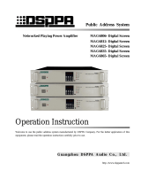
PROFESSIONAL DIGITAL CONFERENCE SYSTEM
D6201
USB
1 2 3 4 5
Functions on front panel of the controller:
1. Power switch (POWER)
Power is on when the button is pushed
down and is off when the button is
ejected.
2. Power indicating light (ON)
The indicating light will be on, when the
system is powered on, and it is off when
the system is powered off.
3. USB port (USB)
For connection of USB flash disks
during the recording process;
A mouse with USB port may be
connected to operate the system.
4. LCD touch screen display
For display of function icons and menus
in the operation process; touch screen is
used in configuration.
5. Screw holes for installation in cabinet
2.2 Rear panel
广州市迪士普音响科技有限公司
Guangzhou DSPPA Audio Co.,Ltd.
请勿打开,以免触电
RISK OF ELECTRIC SHOCK
DO NOT OPEN
警告
CAUTION!
AC220V~50Hz 320W
F2AL250V
ALARM
IN
LINE
IN
1 2 3 4
5 6
-
+
商标:
型号:D6201
品名:会议主机
9
1
2
3
4
5
7
8
6
9
1
2
3
4
5
7
8
6
9
1
2
3
4
5
7
8
6
9
1
2
3
4
5
7
8
6
9
1
2
3
4
5
7
8
6
8 9 10 11 12 13
2000m

* * Conference Host
3
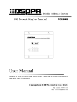
Functions on rear panel of the controller:
1. Warning audio signal input port (ALARM IN)
It is used for connection to warning signals
from the fire control center and is interlocked
to the warning triggering signal as mentioned
in ⑨.
2. Line audio signal input port (LINE IN)
It is for connection of sound source or sound
console equipment to provide line audio signal
to this system.
3. Mix output of audio signal (LINE OUT)
It is for connection of amplifiers, and the
output signal includes line audio signals,
warning signals and microphone signals.
4. Port for connection of interpreter controller to
the system
(INTERPRET)
5. Extension port (ROUTE)
It is used to connect the conference controller
and extension controllers and to transmit audio
signals and communication signals.
6. Conference unit output port (3-way output,
DELEGATES1-3)
The three ports allows connection of up to 128
conference units.
7. Port for central control system (CONTROL
SYSTEM)
It is used to connect the system to a smart
central control system, to realize centralized
control over the conference system by far
infrared.
8. Camera control port (RS422)
It is used for connection of control signals of 4
cameras, which are connected in serial manner.
9. Fire alarm interlocking and activation port
(ALARM ACTIVE)
The system adopts +5V voltage to trigger the
alarm interlocking, in which "Alarm" will be
displayed on the screen of all conference units
and the microphones of all conference units
will be deactivated.
When the +5V voltage on this port is off, the
system will automatically return to the
working status before such alarm.
10. Ethernet port (PC)
The conference can realize remote control via
TCP/IP network;
When the system is connected to a WIFI
network, it allows wireless conference control
via a tablet PC.
11. Fuse in power supply of the system
F2AL250V fuse socket;
If the fuse is blown, please replace it with a
fuse of the same specification;
If the fuse is blown, it indicates equipment
fault, so please replace the fuse after such fault
has been eliminated;
See description on Page 30 for procedures of
replacing the fuse.
12. Power input
AC220V/50Hz/320W power input.
13. Grounding connection
It is used to connect the conference controller
to the ground, so as to avoid electric shock or
equipment damages caused by electric
leakage.
14. Mix output of audio signals (Cannon balance
output socket)
This port is connected in parallel to output port
as mentioned in ③ (LINE OUT), and is a
balance output socket. The signals on the three
pins are defined as below:
15. 6 common cameras connection ports
Each port allows connection to one camera;
All 6 cameras connected to this system must
be of the same brand;
Cameras are connected by coaxial cable.
16. HD video output interface
Connect the projector and other video equipment,
Input the camera content to the big screen
17. Common Video output port
The port is used for connection to projectors or
other video equipment, with which the content
captured by cameras will be output to a large
1
2
3
GND
Reverse input
Obverse input
Three-wire Cannon plug

* * Conference Host
4
screen.
18. 6 HD camera connection port
Each port allows connection to one camera;
All 6 cameras connected to this system must
be of the same brand;
Cameras are connected by coaxial cable.
19. This label means "applies only to areas under
2000 meters above sea level and safe use in
non-tropical climate conditions.”
3. Connection
3.1 System connection
广州市迪士普音响科技有限公司
Guangzhou DSPPA Audio Co.,Ltd.
请勿打开,以免触电
RISK OF ELECTRIC SHOCK
DO NOT OPEN
警告
CAUTION!
AC220V~50Hz 320W
F2AL250V
ALARM
IN
LINE
IN
1 2 3 4
5 6
-
+
商标:
型号:D6201
品名:会议主机
9
1
2
3
4
5
7
8
6
9
1
2
3
4
5
7
8
6
9
1
2
3
4
5
7
8
6
9
1
2
3
4
5
7
8
6
9
1
2
3
4
5
7
8
6
2000m
PROFESSIONAL DIGITAL CONFERENCE SYSTEM D6237
PROFESSIONAL DIGITALCONFERENCE SYSTEM D6233B
PRIORITY
TALK
PROFESSIONAL DIGITALCONFERENCE SYSTEM D6234B
TALK
D6222
D6231
D6222
Extender
Extender
D6234B
D6237
D6236
D6234B
Projector
Central control system
Router
LAN/WLAN
PC
Pad
Amp.
Fire alarm system
DVDPlayer
Alarm trigger signal
Alarm trigger signal

* * Conference Host
5
4. Operation Guide
4.1 Configuration
After all the installation and connection of
the system is completed, the various
functions need to be set for the conference
control host, and all settings must be
completed before the meeting starts.
4.1.1 Boot device
Press the power switch (the blue indicating
light will be on), and the equipment will start
its operating system and then start the
conference control software. After the system
is started, the conference system will be
initialized, which will take some time. After
the initialization, the system will show the
main interface (start interface).
Main functions displayed on the main
interface, excluding system time displayed on
the top, include:
"Number of units connected to the system"
"Speech settings"
"Camera tracking"
"Camera selection"
"Conference mode"
"EQ Control"
"Recording operation"
"System settings"
Users can access the corresponding operating
interface by touching these icons on the touch
screen.
4.1.2 Play Music
Touch the "song play" icon on the main
interface to enter the song playback setting
interface (the first identification of U disk
needs 30s-2min, depending on the U disk
memory size, please wait patiently). Before
the song is played, you must insert the USB
disk that has been recorded into the song as
the sound source. Song playback and
recording cannot be performed at the same
time. The interface is as shown below:
4.1.3 Number of speech
The limit of the number of speech set in this item
is valid in the non-fully open conference mode
(FREE). Users can view the number of active
speech by touching the icon of "Speech" on the
main interface, and enter the configuration interface
of "Allow Speak Number". The interface is shown
below:
The interface indicates the number of currently
active speeches, number of speech application and
the maximum speech allowed, of which the
maximum speech allowed may be modified by
pressing the small arrows in the value box:
1) Touch the UP arrow to increase such value by 1;
2) Touch the DOWN arrow to decrease such value
by 1;
3) The maximum active speeches is 6;
4) After configuration and viewing operations are
completed, touch the icon to close the
unit limit interface and return to the main
interface.
4.1.4 Video follow on-off
On the main interface, touch the "Video follow
on-off" icon to enter the configuration interface of
Set the speak
numbers.

* * Conference Host
6
camera tracking function. As shown below, the
camera tracking function may be enabled or
disabled on this interface. Touch the options, and if
the icon before the option is green as shown below,
it means that the camera tracking function has been
set to the selected status. Firstly, set the status at
"video follow off", and then set the camera to a
preset point (there can be 30 preset points) in the
setting interface to locate and save it, and finally set
the state here as the video follow on state, so that
the camera preset point can be automatically
tracked. It can also be controlled by PC software
(see the PC software control description section for
specific operations) or by the central control.
4.1.5 Camera select
The camera may be selected on conditions that the
camera tracking function is off, otherwise users will
not be able to select the desired camera.
On the main interface, touch the icon of "Camera
Selection" to access the manual camera selection
interface. The interface is as shown below:
The operable functions on the interface as
following:
1) Camera selection: In this system, 6 BNC cameras
and 6 HDMI cameras can be connected. Only
one of them can be selected for operation. In
this operation, one of the cameras is selected
(for example, camera 1 is selected), and other
cameras are mainly configured with the
camera. If the camera is changed (for example,
camera 2 is selected), the camera needs to be
reselected. The camera is set up, including the
"camera tracking switch" setting and the
"camera tracking positioning" setting. When
selecting a camera, touch the icon in front
of one of the cameras so that the icon is
displayed in green to indicate it is selected. 2)
Camera naming: On the "Camera Selection"
interface, the user may touch the "Camera
Naming" icon to access the operation interface
to name the camera. On this interface, the user
may name the six cameras. The default names
are as follows before such cameras are named.
The user does not have to name the cameras
unless he/she has special needs.
Procedures to name a camera:
On the interface as shown above, touch the
"Modify" button after the camera to be
renamed, then a keyboard will show;
Enter the new name of such camera and touch
the "Ent" button to confirm and quit the key
board;
After the operation completes, touch the
on the upper right to exit the interface and
return to the upper interface.
4.1.6 Meeting mode
On the main interface, touch the "Conference
mode" icon to enter the configuration interface of
conference mode, which is as shown below:
There are total 5 meeting mode as following:
“FIFO”
“NORMAL”

* * Conference Host
7
“FREE”
“APPLY”
“VOICE”
a) FIFO mode means first-in-first-out mode.
When the unit is opened to reach the set
quantity, the next unit will turn off the first
unit that is turned on. The total number of
ordinary unit + VIP units can be up to 10 in
total.
b) NORMAL mode is the queuing mode. When
the unit opens and reaches the set quantity,
the unit that was first queued after the
previous unit was turned off is automatically
turned on, and the total number of ordinary
unit + VIP units can be up to 10.
c) FREE is free mode, supports 20 units to
speak at the same time. When the number
reaches 20, the subsequently opened unit
enters the queue for waiting. If the VIP in the
unit is queued, the VIP unit is opened first.
d) APPLY is the application for speaking mode.
The representative unit must apply for the
approval of the chairman unit and open the
application unit to speak. If there is no
application for the VIP unit, the total number
of ordinary unit + VIP units can be up to 10.
e) VOICE is the sound control mode. It needs to
set the voice control sensitivity firstly. When
speaking, it will be close to the unit's
microphone head and it will automatically
open the unit. If there is no speech within 1
minute, the unit microphone will be
automatically turned off.
○1 If the number of normal cells is first
turned on to the set number, the total number
of ordinary cells + VIP cells can be up to 10.
○2 If the VIP unit turns on the quantity to the
set quantity first, and then open the normal
unit, it cannot be turned on.
On the interface, the user can select a mode for the
conference system.
1) Touch the desired conference mode to select (for
example, touch NORMAL to select the NORMAL
mode), the conference is selected when the icon
before such conference mode is in green color.
2) If "VOICE" mode is selected as the conference
mode, then the user needs to set up the sensitivity of
the microphones on conference units. The
procedures for setting up the sensitivity as follows:
When the icon before "VOICE" mode is in green
color, touch the "Sensitivity" button after it will call
the sensitivity setting interface.
On such interface, touch the boxes which indicates
the sensitivity and the boxes becomes blue, it means
that the adjustment has completed.
After the configuration is complete, touch the
"Return" button to exit the sensitivity configuration
interface.
4.1.7 Sound effect
On the main interface, touch the "EQ" icon to enter
the EQ interface, which is as shown below:
On the interface, the user can control the AUX
volume, main volume, low cut, frequency shifter
and equalizer setting.
1) AUX volume: It is used to adjust the volume of
secondary audio input.
2) Main volume: It is used to adjust the volume of
secondary output, alarm output and the volume
of all conference units.
3) Low cut: With this option, the user may decide if
the low frequency under 801Hz will be cut or
not. If this option is selected, (the icon
before the option is green) the low cut function
will be activated, otherwise, it will be in active.
If the low cut function is required, the option
must be properly set up before the conference.
The low cut function may also be configured on
the PC control software.
4) Equalizer: This setting is to choose whether to
use the equalizer function. There are 14 graphic
equalizers in the system. There are multiple
equalization modes. You can manually adjust

* * Conference Host
8
the balance and save the manually adjusted
equalization mode for later recall. If the
equalizer function is selected here, you can
touch the "Settings" button behind it to enter the
equalizer setting interface.
As shown in the picture, the 14 band graphic
equalizer allows manual adjustment. Users may
save the current value as mode 1 to mode 6.
Users need to touch the mode button before
making any adjustment to the equalizer (for
example, "mode 1 is selected").
After the adjustment is completed, touch the
"Save mode" button to save the equalizer
values to "mode 1", so in the future, the user
may touch the "mode 1" button to call the
equalizer values.
4.1.8 Record control
On the main interface, touch the "Recorder" button
to enter the recorder operation interface. The
conference system can realize conference recording,
and the audio file recorded may be saved on a USB
flash disk. Before the recording is started, plug a
USB flash disk to the front panel of the conference
controller, otherwise the recording function cannot
be realized.
The audio file generated by this conference system
will be saved in wav format, which allows direct
playing on most computers.
The system supports "Automatic recording" and
"Manual recording" modes. On the recording
interface as shown above, the user may touch the
desired recording mode to select it.
Automatic recording: If the automatic
recording function is selected, the recording
will start when any speech is delivered via any
conference unit, and it will automatically stop
when the last speaking unit is off. The
recording may stop if there is not enough space
on the USB flash disk.
Manual recording: If manual recording is
selected, the user may start recording by
pressing the "Start" button and stop it by
pressing the "Stop" button. Under manual
recording mode, the recording will also
automatically stop if there is not enough space
on the USB flash disk.
On the recording interface, the user may view
the time length of recording, the file name of
recorded files and the time kept on the USB
flash disk.
Composition of file name:
By default, the file is named by the starting
date and time of the recording in wav format;
for example if the recording starts at 12:30:50
of August 1st, then the audio file will be
named as 08_01_12.30.50.wav. A new audio
file will be generated when the recording is
longer than 1 hour.
4.2 System Configuration
On the main interface, the user can press the
"System Setup" icon and then input the password
(the default password is 111111 and may be
changed by the user) and press the "OK" button to
enter the "System Setup" interface, which is as
shown below:

* * Conference Host
9
The functions provided on the system setup
interface include:
"Network Setup"
"Camera Tracking and Positioning"
"Unit Inspection"
"Unit ID"
"Unit Setup"
"Time Limit for Speeches"
"Microphone On/Off tone"
"System Time"
"Display"
"General"
4.2.1Network setting
The Network setup includes "IP address", "Subnet
mask" and "Gateway" settings of the host controller.
Assign a unique IP address to the conference
controller. Touch the boxes after the "IP
Address" and the cursor starts to blink, at this
time, the user may touch the "Modify" button
to call the "IP Address modification" interface,
in order to modify the IP address. The interface
is as shown below:
Move the input cursor behind the number you want
to change, touch the red “DEL” button to delete the
original number, and then use the numeric keypad
to enter the target number, touch the “OK” button to
confirm and exit the input interface. The procedures
for setting up the subnet mask same as those of IP
address.
The method of setting the subnet mask and
gateway is the same as the IP address setting.
After all the settings are completed, the
interface will automatically pop up a message
saying "requiring system restart to take effect."
Then restart the system.
4.2.2 Camera Tracking and Positioning
The user may touch the "Camera Positioning" icon
on the "System Setup" interface to enter the camera
tracking and positioning setup interface, which is as
shown below:
On this interface, the user may select the desired
communication protocol of cameras and can set up
the swing speed of cameras and can enter the
camera positioning interface for further operation.
Tips: No speech will be delivered on the
conference units during the setup period of
camera tracking and positioning functions.
Communication protocol: D62 series smart
digital conference system provides three
options: PELCO D -9600, PELCO P -9600 and
VISCA -9600. In order to select the desired
option, the user can touch the black arrow after
the protocol box to open the drop-down list,
and then touch the target communication
protocol in the list to complete the whole
operation. The communication protocol may
vary from cameras of different brands,
therefore, all the four cameras connected to the
controller must be products of the same brand.
Swing speed of camera: With this option, the
user can set up the step size when the camera
swings. Larger step size means faster swing
speed, and the swing range will be larger,

* * Conference Host
10
otherwise smaller step size means slower
swing speed, and the swing range will be
smaller. But slower swing speed will result in
better positioning precision. In order to set up
the swing speed, the user may only need to
slide the block to the desired position to
complete the setup process.
Camera positioning: The user may touch the
"Camera Positioning" button on the graphic
interface to enter the setup interface, which is
as shown below:
On this interface, the user may point a camera to a
particular conference unit, and the setting will be
saved for future use. With this interface, the user
may set up 32 conference units which will be
tracked by the cameras and save 32 camera
positioning plans.
To set up the camera positioning, the user should
select a camera (Camera 1# for example) and then
modify the conference unit ID which will be
tracked by the camera (The Unit ID should be the
ID of conference unit to be tracked). The user may
enter the desired unit ID (for example the unit ID is
0001), via a number keyboard, on the interface
shown below, and then the user may use the
button to adjust the position and
focal length when the camera is pointed to such
conference unit;
Finally, the user should save the position
information of cameras. He/she can touch the
"Modify" button after the "Save as preset point" to
enter the modification interface. Then he/she can
touch the preset points (for example "1") and then
touch the "Select" button to complete the operation
and exit the interface. If after the user selects a
preset point, he/she touch the "DEL" button, then
the position information saved on such preset point
will be deleted and the preset point will be in an
idle status. Preset points without position
information are also in idle status.
After modification to the preset points, the user can
touch "Save" button to save the position
information, and in future application, the user may
touch the "Call" button to call the saved position
plans. In each time, the system will call the preset
point after the "saved preset point" (for example,
the number box will display "2").
4.2.3 Microphone unit detection
On the "System Setup" interface, the user can touch
the "Unit Inspection" icon to enter the unit
inspection interface. The interface is as shown
below:
0001

* * Conference Host
11
Before the conference commences, it is necessary to
inspect every conference units. The items to be
inspected include: "microphone, LCD screen,
operation buttons, LED indicating lights and
speaker". Inspection may be done manually or
automatically and the inspection time is also
adjustable. The inspection will be carried out on the
conference units currently displayed, and the ID of
such units will be displayed on the upper left corner
of the interface.
Procedures for automatic inspection:
Touch the "Automatic Inspection" button and
the button is selected if it is highlighted.
Set the "Unit inspection time", which will be
effective in automatic inspection. The time
may be 20-100 seconds. Touch the small
arrows after the "Unit inspection time"
to adjust the time. After the inspection time is
set up, the system will automatically inspect all
inspection items of a conference unit,
including "microphone, LCD Screen, buttons,
LED lights and speaker". After the inspection
on one conference unit is completed, the
system will automatically proceed with the
next one.
In order to stop the automatic inspection,
please touch the "Stop inspection" button.
Tips: No speech will be delivered on the
conference units during inspection to the
conference units.
Procedures for manual inspection:
1) Inspection to microphone
Touch the "Inspect the microphone" button
(the button is selected when it is highlighted in
light blue color);
Touch the "Start Inspection" button to inspect
if the microphone can be activated and
deactivated normally. During the inspection,
the LED on power button and surrounding the
microphone will be on and messages of
"Inspecting" will be displayed on the
inspection interface and the "Start inspection"
button will change to "Stop inspection".
Message of "Microphone is being inspected..."
will be displayed on the LCD screen of the
conference unit.
After the selected conference unit is inspected,
the user can touch the "Stop inspection" button
to stop the inspection and the LED lights on
the conference unit inspected will be off. Or
otherwise, the user may touch the "Previous
Unit" or "Next Unit" to inspect other
conference units connected to the conference
controller and stop the inspection after all
conference units are inspected.
2) Inspection to LCD screen
Touch the "Inspection to LCD Screen" button
and the button is selected if it is highlighted.
Touch the "Start inspection" button to inspect
the LCD screen of the selected unit.
Touch the "Previous Unit" or "Next Unit" to
inspect other conference units connected to the
controller.
3) Inspection to buttons
Touch the "Inspection to Buttons" button and
the button is selected if it is highlighted.
Touch the "Start inspection" button to enter
unit button inspection status, and then the user
should press the buttons on each conference
unit to see if they work properly. When the
user press a function button, if the
corresponding indicating light is on and then is
automatically off, it means that the button can
work properly.
After inspection to all buttons, the user should
touch the "Stop inspection" button to stop the
inspection, or he/she can touch other
inspection item to continue with the
inspection.
4) Inspection to LED indicating light
Touch the "Inspection to LED" button and the
button is selected if it is highlighted.
Touch the "Start inspection" button to enter
Unit LED inspection status, and then all LED
indicating lights on the conference units being
inspected will blink.
The user may touch the "Stop inspection"
button to stop the inspection, or he/she can
touch other inspection item to continue with
the inspection.
5) Inspection to speaker
Touch the "Inspection to speaker" button and
the button is selected if it is highlighted.
Touch the "Start inspection" button to enter the
unit speaker inspection status, and the speakers
of conference units being inspected will beep,
this means that the speaker can work properly.
The user may touch the "Stop inspection"
button to stop the inspection, or he/she can
touch other inspection item to continue with
the inspection.
After all inspection items are completed, the user
should touch the icon to exit the inspection

* * Conference Host
12
interface.
4.2.4 Microphone unit set ID
Touch the "Unit numbering" button on the "System
setup" interface to enter the unit numbering
interface which is as shown below:
On this interface, the user can renumber all the
existing conference units and number the newly
connected units.
1) Renumbering
On the "Unit Numbering" interface, the user
can touch the "Renumber" button to enter the
renumbering interface which is as shown
below:
On the interface shown above, the user should
set up the unit ID on the conference units to be
renumbered (please refer to the description on
conference setup section for information with
respect to unit numbering operations). After
the operation has completed, the user should
touch the "End" button as shown above, to exit
the interface.
After all conference units are numbered, the
unit IDs renumbered will take effect after the
conference controller is power off and
restarted.
2) Add new ID
On the "Unit Numbering" interface, the user
can touch the "Add new ID" button to enter the
operation interface which is as shown below:
The user should set up the IDs on newly added
conference units and after the setup operation,
he/she should touch the "END" button on the
interface shown above to exit the interface.
After all new conference units are numbered,
the newly added unit IDs will take effect after
the conference controller is power off and
restarted.
After the conference units are numbered, the user
may touch the icon on the upper right corner
of the "Unit Numbering" interface to exit the
numbering interface.
Tips: After the conference units are renumbered,
the camera tracking information and the
chairman unit assigned will be deleted, so the
user needs to reset them.
4.2.5 Conference microphone setting
Touch the "Unit Setup" button on the "System
setup" interface to enter the unit setup interface
which is as shown below:
On the unit setup interface, the following setup
operations are available:
"Chairman unit 1"
"Chairman unit 2"
"Platform mode"
"Priority"
"Vote result display"
"Setting of VIP units"
1) Chairman unit
D62 series smart digital conference system allows 2

* * Conference Host
13
chairman units which are given the priority to make
speeches, and they can operate simultaneously. The
setup procedures are as follows:
On the "Unit Setup" interface, touch and select
the "Chairman Unit" (for example, Chairman
Unit 1 is selected). When an option is selected,
the icon before such option will be
displayed in green color.
Touch the black arrow after the ID box of
conference unit to unfold the drop-down list,
and select the ID from the menu for "Chairman
Unit 1" or "Chairman Unit 2".
After all conference units are numbered and
the conference system is restarted, the
Chairman Units will be automatically
identified and its ID will be displayed in the
list on the operation interface.
The ID of conference unit set as a Chairman
unit will be displayed on the following
interface.
If ten chairman units are connected to the system,
then after all conference units are renumbered, all
the ten chairman units will be identified by the
conference controller and will be displayed on the
list as shown above.
2) Platform mode
To set up the platform on/off status of
Chairman Unit 1 and Chairman Unit 2, the
user may simply touch the desired option to
complete the setup operation.
If the Platform mode is "ON", then both the
two chairman units will be always on and the
ON/OFF button the chairmen unit will be
ineffective; if the platform is "OFF", the
chairman unit will be operated by the On/Off
button on such units.
3) Priority
The user may set the priority of Chairman Unit
1 and Chairman Unit 2 as "Mute" or "Off".
The user may touch the options after "Priority"
on this interface to complete the setup.
If "Mute" is selected, then in the conference,
when the chairman presses the priority button,
then all activated conventioner unit will be
turned to mute status. After the activated
conventioner unit is mute, the On/Off LED
light on the microphone will blink, and a
sound off message will be displayed on LCD
screens of the Chairman unit and the
conventioner units. Please refer to the
description of conference unit setup section for
detailed information as the content displayed
and the operation instructions. If it is no longer
necessary to turn off the microphones of
conventioner units, they chairman may press
the priority button and cancel the sound off
status by following the instructions on the
LCD screen, the conventioner unit will be able
to deliver speeches.
If "Off" is selected, then in the conference,
when the chairman presses the priority button,
then all activated conventioner unit will be
turned off.
4) Vote result display (Only effective on units with
LCD screen)
With this option, the user may decide if the
vote result will be displayed on all conference
units including the Chairman Unit 1 and
Chairman Unit 2. The user may touch the
options after "Vote Result Display" button to
complete the setup.
If "YES" is selected, then the vote result will
be displayed on all conference units; of "NO"
is selected, then the vote results will not be
displayed on LCD screens of any conference
unit other than the chairman unit 1 and 2.
5) Setting of VIP units
The user may touch the "VIP Unit Setup" button on
the "Unit Setup" interface to enter the VIP unit
setup interface which is as shown below:
D62 series smart digital conference system allows a
maximum number of 30 VIP units. The VIP unit
may be a conference unit of whatever type. When
the total activated conference unit is less than 20
under FREE mode and 10 under any other mode,
the VIP unit is free from limitation of conference
mode and may be turned on/off freely.
On the interface shown above, the user may
add new VIP units by touching the "ADD"
button. The conference system allows a
Touch here to
show the list of
all Chairman
units.

* * Conference Host
14
maximum number of 30 VIP units. Touch the
"ADD" button to enter the VIP unit operation
interface:
On the interface as shown above, they user may
enter the ID of conference unit to be set as a VIP
unit, and then touch the "OK" button to confirm and
exit the interface.
The user can touch the "DEL" button to delete
the VIP unit selected.
They user may touch the "DELETE ALL"
button to delete all existing VIP units.
With the "Return" button or by touching the
icon, the user can exit VIP setup interface and
return to the unit setup interface.
After the unit setup is completed, the user may
touch the icon on the upper right corner to exit
the unit setup interface and return to the main
interface of the system.
4.2.6 Set speak time
The user may touch the "Timing of Speeches"
button on the "System Setup" interface to enter the
timing setup interface which is as shown below:
On this interface, the user can set up the time limit
for speeches of conventioners and the speech unit
will be automatically shut off when the time is over.
The time limit can be any value between 1 and 300
minutes. D62 series digital conference system
provides a countdown warning function, and the
user can set up the countdown time in this interface,
which should be with the range between 1 and 60
seconds. The countdown will also be displayed on
the speech unit. If the speech timing function is not
needed in the conference, then it can be set as
"OFF".
The user can adjust the values of time limit and
countdown function to the desired value by
touching the small gray arrows after the time
indication .
After the time value setup is completed, the user
may touch the icon on the upper right corner
to exit the setup interface and return to the main
interface of the system.
4.2.7 Chime set
The user may touch the "Ring tone" icon on the
"System Setup" interface to enter the ring tone
setup interface which is as shown below:
Select the prompt tone when the microphone is
turned on or off. The options available for setup
includes:
"No ring tone"
"Ring tone 1"
"Ring tone 2"
"Ring tone 3"
1) "No ring tone" means that there is no indicating
sound when the microphone of conference unit is
powered on or off.
2) "Ring tone 1- Ring tone 3" indicates that one of
the ring tones will be played when the microphone
on the conference unit is turned on/off.
4.2.8 Set system time
The user may touch the "Time" icon on the "System
Setup" interface to enter the system time setup
interface which is as shown below:
Enter the ID of unit to
be set as a VIP unit.

* * Conference Host
15
The current system time can be adjusted on this
interface. The system time set here is displayed on
the top edge of the main interface.
1) To set the system time, the user can touch the
gray arrows respectively after the values of Year,
Month, Data, Hour, Minute and Second to
adjust the system time.
2) After the setup is completed, the user should
touch the "OK" button to confirm and exit the
system time setup interface.
4.2.9 Display setting
The user can touch the "Display" icon on the
"System Setup" interface to enter the conference
controller LCD screen setup interface. The
options available for setup include:
"Backlight on time"
"Touch screen calibration"
1) Backlight on time
This is the time or status set for the backlight of
LCD screen on the conference controller.
After the user sets up the backlight times, if
there is no operation on the equipment within
such period of time, the back light of LCD
screen will be off and it will be on again if any
operation is made on the equipment, so that it
helps to save energy and to extend the service
life of LCD screen. The backlight time may be
any value between 1 and 240 minutes.
If the backlight is set as "Always On", then the
backlight will be on for the period after the
equipment is powered on and before it is
powered off.
The user can touch the gray arrows after the
"backlight time" to adjust the option or
backlight time.
2) Touch screen calibration
After the equipment is used for a certain period, due
to the rise of temperature or other factors, the touch
point is not precise and it may be hard to move the
touch point to the desired operation item, at such
time, the user needs to calibrate the touch screen by
following the following procedures:
Touch the "Screen Calibration" button on the
"Display Setup" interface to enter the screen
calibration interface.
After the touch screen is in the calibration
status, the system will automatically restart
and enter the screen calibration interface after
a while.
On the calibration interface, the user should
touch the center of the small circle on the
screen with the sharp end of the pen (Note:
Touch the exact center of the circle).
Repeat the calibration on all four corners and
the center of the touch screen, otherwise, it
will be hard to move the cursor to the desired
option. In such cases, the user can connect a
USB mouse to the system to enter the touch
screen calibration interface, in order to restart
the system and complete the calibration. Or
otherwise, the user may also operate the
system by using the mouse.
Notice:
During touch screen calibration, it is very
important to point the pen to the center of the
"+", otherwise the user may not be able to
operate the system. The touch pen should be
used to operate the touch screen during the
calibration, which helps to reduce the chances of
misoperation.
4.2.10 General setting
The user may touch the "General" icon on the
"System Setup" interface to enter the general setup
interface which is as shown below:
The options on the general setup interface includes:
"Language"
"Export configuration file to USB flash disk"
"Import configuration file to the system"
"Modify the Password on the Equipment"
"Machine Code of this Equipment"
1) Language selection
With this option, the user can setup the display
language for the system. The conference system
supports Chinese and English languages. Touch
the small arrow after the language bar to open
Touch here to adjust
the options or time
value to complete
the setup.
/