Page is loading ...

www.infineon.com
Please note that Cypress is an Infineon Technologies Company.
The document following this cover page is marked as “Cypress” document as this is the
company that originally developed the product. Please note that Infineon will continue
to oer the product to new and existing customers as part of the Infineon product
portfolio.
Continuity of document content
The fact that Infineon oers the following product as part of the Infineon product
portfolio does not lead to any changes to this document. Future revisions will occur
when appropriate, and any changes will be set out on the document history page.
Continuity of ordering part numbers
Infineon continues to support existing part numbers. Please continue to use the
ordering part numbers listed in the datasheet for ordering.

www.cypress.com Document No. 001-76405 Rev. *J 1
AN76405
EZ-USB® FX3™/FX3S™ Boot Options
Author: Sai Krishna Vakkantula
Associated Part Family: CYUSB30xx
Related Application Notes: AN75705
More code examples? We heard you.
For a consolidated list of USB SuperSpeed Code Examples, visit http://www.cypress.com/101781.
AN76405 describes the boot options—over USB, I
2
C, serial peripheral interface (SPI), and synchronous Address Data
Multiplexed (ADMux) interfaces—available for the Cypress EZ-USB
®
FX3™ peripheral controller. This application note
is also applicable to FX3S and CX3 peripheral controllers.
Contents
1 Introduction .................................................................. 2
2 More Information ......................................................... 2
2.1 EZ-USB FX3 Software Development Kit ............. 2
2.2 GPIF™ II Designer .............................................. 2
3 FX3 Boot Options ........................................................ 3
4 USB Boot ..................................................................... 4
4.1 PMODE Pins ....................................................... 4
4.2 Features .............................................................. 4
4.3 Checksum Calculation ........................................ 8
4.4 Boot Image Format ........................................... 11
5 I
2
C EEPROM Boot ..................................................... 12
5.1 Features ............................................................ 13
5.2 Storing Firmware Image on EEPROM .............. 13
5.3 Boot Image Format ........................................... 15
5.4 Checksum Calculation ...................................... 16
6 I
2
C EEPROM Boot with USB Fallback ....................... 18
6.1 Features ............................................................ 18
6.2 Example Image for Boot with VID and PID ....... 18
7 SPI Boot .................................................................... 19
7.1 Features ............................................................ 19
7.2 Selection of SPI Flash ....................................... 20
7.3 Storing Firmware Image on
SPI Flash/EEPROM .......................................... 20
7.4 Boot Image Format ........................................... 21
7.5 Checksum Calculation ...................................... 22
8 SPI Boot with USB Fallback ...................................... 23
8.1 Example Image for Boot with VID and PID ....... 23
9 Synchronous ADMux Boot ........................................ 24
9.2 Boot Image Format ........................................... 36
10 eMMC Boot ............................................................... 38
11 Default State of I/Os During Boot .............................. 39
12 Related Documents ................................................... 40
A Appendix A: Steps for Booting Using
FX3 DVK Board (CYUSB3KIT-001) .......................... 41
A.1 USB Boot .......................................................... 42
A.2 I
2
C Boot ............................................................ 46
A.3 SPI Boot ............................................................ 51
B Appendix B: Troubleshooting Steps for
Sync ADMux Boot ..................................................... 56
B.1 Initialization ....................................................... 56
B.2 Test Register Read/Write .................................. 56
B.3 Test FIFO Read/Write ....................................... 56
B.4 Test Firmware Download .................................. 57
C Appendix C: Using the elf2img
Utility to Generate Firmware Image ........................... 59
C.1 Usage ............................................................... 59
C.2 Image Type ....................................................... 59
C.3 I2C Parameters ................................................. 59
C.4 SPI Parameters ................................................ 60

EZ-USB® FX3™/FX3S™ Boot Options
www.cypress.com Document No. 001-76405 Rev.*J 2
1 Introduction
EZ-USB FX3 is the next-generation USB 3.0 peripheral controller, providing highly integrated and flexible features that
enable developers to add USB 3.0 functionality to a wide range of applications. FX3 supports several boot options,
including booting over USB, I
2
C, SPI, synchronous and asynchronous ADMux, and asynchronous SRAM interfaces.
Note: This application note describes the details of only the USB, I
2
C, SPI, and synchronous ADMux boot options.
The default state of the FX3 I/Os during boot is also documented. Appendix A covers the stepwise sequence for testing
the different boot modes using the FX3 DVK.
2 More Information
Cypress provides a wealth of data at www.cypress.com to help you to select the right device for your design, and to
help you to integrate the device into your design quickly and effectively.
▪
Overview: USB Portfolio, USB Roadmap
▪
USB 3.0 Product Selectors: FX3, FX3S, CX3, HX3
▪
Application notes: Cypress offers a large number of USB application notes covering a broad range of topics, from
basic to advanced level. Recommended application notes for getting started with FX3 are:
AN75705 – Getting Started with EZ-USB FX3
AN70707 – EZ-USB FX3/FX3S Hardware Design Guidelines and Schematic Checklist
AN65974 – Designing with the EZ-USB FX3 Slave FIFO Interface
AN75779 – How to Implement an Image Sensor Interface with EZ-USB FX3 in a USB Video Class (UVC)
Framework
AN86947 – Optimizing USB 3.0 Throughput with EZ-USB FX3
AN84868 – Configuring an FPGA over USB Using Cypress EZ-USB FX3
AN68829 – Slave FIFO Interface for EZ-USB FX3: 5-Bit Address Mode
AN76348 – Differences in Implementation of EZ-USB FX2LP and EZ-USB FX3 Applications
AN89661 – USB RAID 1 Disk Design Using EZ-USB FX3S
▪
Code Examples:
USB Hi-Speed
USB Full-Speed
USB SuperSpeed
▪
Technical Reference Manual (TRM):
EZ-USB FX3 Technical Reference Manual
▪
Development Kits:
CYUSB3KIT-003, EZ-USB FX3 SuperSpeed Explorer Kit
CYUSB3KIT-001, EZ-USB FX3 Development Kit
▪
Models: IBIS
2.1 EZ-USB FX3 Software Development Kit
Cypress delivers the complete software and firmware stack for FX3 to easily integrate SuperSpeed USB into any
embedded application. The Software Development Kit (SDK) comes with tools, drivers, and application examples,
which help accelerate application development.
2.2 GPIF™ II Designer
The GPIF II Designer is a graphical software that allows designers to configure the GPIF II interface of the EZ-USB
FX3 USB 3.0 Device Controller.

EZ-USB® FX3™/FX3S™ Boot Options
www.cypress.com Document No. 001-76405 Rev.*J 3
The tool allows users the ability to select from one of five Cypress-supplied interfaces, or choose to create their own
GPIF II interface from scratch. Cypress has supplied industry-standard interfaces such as asynchronous and
synchronous Slave FIFO, and asynchronous and synchronous SRAM. Designers who already have one of these pre-
defined interfaces in their system can simply select the interface of choice, choose from a set of standard parameters
such as bus width (x8, 16, x32) endianness, clock settings, and then compile the interface. The tool has a streamlined
three-step GPIF interface development process for users who need a customized interface. Users can first select their
pin configuration and standard parameters. Secondly, they can design a virtual state machine using configurable
actions. Finally, users can view the output timing to verify that it matches the expected timing. After this three-step
process is complete, the interface can be compiled and integrated with FX3.
3 FX3 Boot Options
FX3 integrates a bootloader that resides in the masked ROM. The function of the bootloader is to download the FX3
firmware image from various interfaces such as USB, I
2
C, SPI, or GPIF II (for example, synchronous ADMux,
asynchronous SRAM, or asynchronous ADMux).
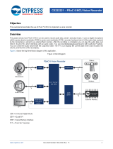
The FX3 bootloader uses the three PMODE input pins of FX3 to determine the boot option to be used. Figure 1 shows
the boot options discussed in this application note. Table 1 lists these boot options along with the required PMODE pin
settings.
Figure 1. FX3 Boot Options
USB Host
Boot over
USB2.0
Bootloader
ROM
External FPGA/
Processor
PMODE2
PMODE1
PMODE0
SPI
I
2
C
Sync
ADMux
EZ-USB FX3
Sync
ADMux
I
2
C EEPROM
SPI Flash
Boot from an
I
2
C EEPROM
Boot from
SPI Flash
Boot over
Sync ADMux
Table 1. Boot Options for FX3*
PMODE[2:0] Pins
Boot Option
USB Fallback
PMODE[2]
PMODE[1]
PMODE[0]
Z
0
0
Sync ADMux (16-bit)
No
Z
1
1
USB Boot
Yes
1
Z
Z
I
2
C
No
Z
1
Z
I
2
C USB
Yes
0
Z
1
SPI USB
Yes
1
0
0
eMMC**
No
0
0
0
eMMC** USB
Yes
Other combinations are reserved.
Notes:
* Z = Float. The PMODE pin can be made to float either by leaving it unconnected or by connecting it to an FPGA I/O
and then configuring that I/O as an input to the FPGA.
**: eMMC boot is only supported by FX3S.

EZ-USB® FX3™/FX3S™ Boot Options
www.cypress.com Document No. 001-76405 Rev.*J 4
In addition to the boot options listed in Table 1, FX3 supports booting from asynchronous SRAM and asynchronous
ADMux interfaces. Contact Cypress Applications Support for details. The following sections describe the boot options
supported by FX3:
▪
USB Boot: The FX3 firmware image is downloaded into the FX3 system RAM from the USB Host.
▪
I
2
C EEPROM Boot: The FX3 firmware image is programmed into an external I
2
C EEPROM, and on reset, the
FX3 bootloader downloads the firmware over I
2
C.
▪
SPI Boot: The FX3 firmware image is programmed into an external SPI flash or SPI EEPROM, and on reset, the
FX3 bootloader downloads the firmware over SPI.
▪
Synchronous ADMux Boot: The FX3 firmware image is downloaded from an external processor or an FPGA
connected to the FX3 GPIF II interface.
4 USB Boot
Figure 2 shows the system diagram for FX3 when booting over USB.
Figure 2. FX3 System Diagram
EZ-USB FX3
USB Host
Boot over
USB2.0
Bootloader
ROM
External FPGA/
Processor
PMODE2=Z
PMODE1=1
PMODE0=1
4.1 PMODE Pins
For USB boot, the state of the PMODE[2:0] pins should be Z11, as shown in Table 2.
Table 2. PMODE Pins for USB Boot
PMODE[2]
PMODE[1]
PMODE[0]
Z
1
1
Note: Z = Float
4.2 Features
The external USB Host can download the firmware image to FX3 in USB 2.0 mode. FX3 enumerates as a USB Vendor
class device with bus-powered support.
The state of FX3 in USB boot mode is as follows:
▪
USB 3.0 (SuperSpeed) signaling is disabled.
▪
USB 2.0 (High Speed/Full Speed) is enabled.
▪
FX3 uses the vendor command A0h for firmware download/upload. This vendor command is implemented in the
bootloader. (Unlike FX2LP™, the A0h vendor command is implemented in firmware; that is, in the bootloader
code.)
4.2.1 Default Silicon ID
By default, FX3 has the default Cypress Semiconductor VID=04B4h and PID=00F3h stored in the ROM space. This
VID/PID is used for default USB enumeration unless the eFUSE
1
VID/PID is programmed. The default Cypress ID
values should be used only for development purposes. Users must use their own VID/PID for final products. A VID is
obtained through registration with the USB-IF.
1
eFUSE is the technology that allows reprogramming of certain circuits in the chip. Contact your Cypress representative for details
on eFUSE programming.

EZ-USB® FX3™/FX3S™ Boot Options
www.cypress.com Document No. 001-76405 Rev.*J 5
4.2.2 Bootloader Revision
The bootloader revision is stored in the ROM area at the address FFFF_0020h, as shown in Table 3.
Table 3. Bootloader Revision
Minor revision
FFFF_0020h
Major revision
FFFF_0021h
Reserved bytes
FFFF_0022h, FFFF_0023h
4.2.3 Re Nu me ra ti on™
Cypress’s ReNumeration feature is supported in FX3 and is controlled by firmware.
When first plugged into a USB Host, FX3 enumerates automatically with its default USB descriptors. Once the firmware
is downloaded, FX3 enumerates again, this time as a device defined by the downloaded USB descriptor information.
This two-step process is called “ReNumeration.”
4.2.4 Bus-Powered Applications
The bootloader enumerates in the bus-powered mode. FX3 can fully support bus-powered designs by enumerating
with less than 100 mA, as required by the USB 2.0 specification.
4.2.5 USB Fallback Options (--> USB)
When booting over other options with USB fallback enabled, FX3 will fall back to the same USB boot mode described
in this section. The operating current may be slightly higher than the USB boot mode due to other clock sources being
turned ON.
4.2.6 USB with VID/PID Options
The bootloader supports booting with a new VID/PID that may be stored in the following:
▪
I
2
C EEPROM: See the I2C EEPROM Boot section of this application note.
▪
SPI EEPROM: See the SPI Boot section of this application note.
▪
eFUSE (VID/PID): Contact Cypress Sales for custom eFUSE VID/PID programming.
4.2.7 USB Default Device
The FX3 bootloader consists of a single USB configuration containing one interface (interface 0) and an alternative
setting of '0'. In this mode, only endpoint 0 is enabled. All other endpoints are turned OFF.
4.2.8 USB Setup Packet
The FX3 bootloader decodes the SETUP packet that contains an 8-byte data structure defined in Table 4.
Table 4. Setup Packet
Byte
Field
Description
0
bmRequestType
Request type: Bit7: Direction
Bit6–0: Recipient
1
bRequest
This byte will be A0h for firmware download/upload vendor command.
2-3
wValue
16-bit value (little-endian format)
4-5
wIndex
16-bit value (little-endian format)
6-7
wLength
Number of bytes
Note: Refer to the USB 2.0 Specification for the bitwise explanation.

EZ-USB® FX3™/FX3S™ Boot Options
www.cypress.com Document No. 001-76405 Rev.*J 6
4.2.9 USB Chapter 9 and Vendor Commands
The FX3 bootloader handles the commands in Table 5.
Table 5. USB Commands
bRequest
Descriptions
00
GetStatus: Device, Endpoints, and Interface
01
ClearFeature: Device, Endpoints
02
Reserved: Returns STALL
03
SetFeature: Device, Endpoints
04
Reserved: Returns STALL
05
SetAddress: Handle in FX3 hardware
06
GetDescriptor: Devices’ descriptors in ROM
07
Reserved: Returns STALL
08h
GetConfiguration: Returns internal value
09h
SetConfiguration: Sets internal value
0Ah
GetInterface:Rreturns internal value
0Bh
SetInterface: Sets internal value
0Ch
Reserved: Returns STALL
20h-9Fh
Reserved: Returns STALL
A0h
Vendor Commands: Firmware upload/download and so on
A1h-FFh
Reserved: Returns STALL
4.2.10 USB Vendor Commands
The bootloader supports the A0h vendor command for firmware download and upload. The fields for the command are
shown in Table 6 and Table 7.
Table 6. Command Fields for Firmware Download
Byte
Field
Value
Description
0
BmRequestType
40h
Request type: Bit7: Direction
Bit6-0: Recipient.
1
bRequest
A0h
This byte will be A0 for firmware download/upload vendor command.
2-3
WValue
AddrL (LSB)
16-bit value (little endian format)
4-5
WIndex
AddrH (MSB)
16-bit value (little endian format)
6-7
wLength
Count
Number of bytes
Table 7. Command Fields for Firmware Upload
Byte
Field
Value
Description
0
BmRequestType
C0h
Request type: Bit7: Direction
Bit6-0: Recipient.
1
bRequest
A0h
This byte will be A0 for firmware download/upload vendor command.
2-3
WValue
AddrL (LSB)
16-bit value (little endian format)
4-5
WIndex
AddrH (MSB)
16-bit value (little endian format)
6-7
wLength
Count
Number of bytes

EZ-USB® FX3™/FX3S™ Boot Options
www.cypress.com Document No. 001-76405 Rev.*J 7
Table 8. Command Fields for Transfer of Execution to Program Entry
Byte
Field
Value
Description
0
bmRequestType
40h
Request type: Bit7: Direction
Bit6-0: Recipient
1
bRequest
A0h
This byte will be A0 for firmware download/upload vendor command.
2-3
wValue
AddrL (LSB)
32-bit Program Entry
4-5
wIndex
AddrH (MSB)
32-bit Program Entry>>16
6-7
wLength
0
This field must be zero.
In the transfer execution entry command, the bootloader will turn off all the interrupts and disconnect the USB. Three
examples of vendor command subroutines follow.
Example 1. Vendor Command Write Data Protocol With 8-Byte Setup Packet
bmRequestType = 0x40
bRequest = 0xA0;
wValue = (WORD)address;
wIndex = (WORD)(address>>16);
wLength = 1 to 4K-byte max
This command will send DATA OUT packets with a length of transfer equal to wLength and a DATA IN Zero length
packet.
Example 2. Reading Bootloader Revision with Setup Packet
bmRequestType = 0xC0
bRequest = 0xA0;
wValue = (WORD)0x0020;
wIndex = (WORD)0xFFFF;
wLength = 4
This command will issue DATA IN packets with a length of transfer equal to wLength and a DATA OUT Zero length
packet.
Example 3. Jump to Program Entry With 8-Byte Setup Packet (refer to Table 8.)
bmRequestType = 0x40
bRequest = 0xA0;
wValue = Program Entry (16-bit LSB)
wIndex = Program Entry >>16 (16-bit MSB)
wLength = 0
Note: FX3 uses 32-bit addressing. Addresses should be written to the wValue and wIndex fields of the command.
4.2.11 USB Download Sample Code
To download the code, the application should read the firmware image file and write 4K sections at a time using the
vendor write command. The size of the section is limited to the size of the buffer used in the bootloader.
Note The firmware image must be in the format specified in Table 14.
The following is an example of how the firmware download routine can be implemented.
DWORD dCheckSum, dExpectedCheckSum, dAddress, i, dLen;
WORD wSignature, wLen;
DWORD dImageBuf[512*1024];
BYTE *bBuf, rBuf[4096];
fread(&wSignature,1,2,input_file);/*fread(void *ptr, size_t size, size_t
count, FILE *stream)

EZ-USB® FX3™/FX3S™ Boot Options
www.cypress.com Document No. 001-76405 Rev.*J 8
read signature bytes. */
if (wSignature != 0x5943) // check ‘CY’ signature byte
{
printf(“Invalid image”);
return fail;
}
fread(&i, 2, 1, input_file); // skip 2 dummy bytes
dCheckSum = 0;
while (1)
{
fread(&dLength,4,1,input_file); // read dLength
fread(&dAddress,4,1,input_file); // read dAddress
if (dLength==0) break; // done
// read sections
fread(dImageBuf, 4, dLength, input_file);
for (i=0; i<dLength; i++) dCheckSum += dImageBuf[i];
dLength <<= 2; // convert to Byte length
bBuf = (BYTE*)dImageBuf;
while (dLength > 0)
{
dLen = 4096; // 4K max
if (dLen > dLength) dLen = dLength;
VendorCmd(0x40, 0xa0, dAddress, dLen, bBuf); // Write data
VendorCmd(0xc0, 0xa0, dAddress, dLen, rBuf); // Read data
// Verify data: rBuf with bBuf
for (i=0; i<dLen; i++)
{
if (rBuf[i] != bBuf) { printf(“Fail to verify image”); return
fail; }
}
dLength -= dLen;
bBuf += dLen;
dAddress += dLen;
}
}
// read pre-computed checksum data
fread(&dExpectedChecksum, 4, 1, input_file);
if (dCheckSum != dExpectedCheckSum)
{
printf(“Fail to boot due to checksum error\n”);
return fail;
}
// transfer execution to Program Entry
VendorCmd(0x40, 0xa0, dAddress, 0, NULL);
input_file is the FILE pointer that points to the firmware image file, which is in the format specified in Table 14.
4.3 Checksum Calculation
In USB download, the download tool is expected to handle the checksum computation as shown in the USB Download
Sample Code section.
4.3.1 FX3 Bootloader Memory Allocation
The FX3 bootloader allocates 1280 bytes of data tightly-coupled memory (DTCM) from 0x1000_0000 to 0x1000_04FF
for its variables and stack. The firmware application can use it as long as this area remains uninitialized, that is,
uninitialized local variables, during the firmware download.
The bootloader allocates the first 16 bytes from 0x4000_0000 to 0x4000_000F for warm boot and standby boot. These
bytes should not be used by firmware applications.
The bootloader allocates about 10K bytes from 0x4000_23FF for its internal buffers. The firmware application can use
this area as the uninitialized local variables/buffers.
The bootloader does not use the instruction tightly-coupled memory (ITCM).

EZ-USB® FX3™/FX3S™ Boot Options
www.cypress.com Document No. 001-76405 Rev.*J 9
4.3.2 Registers/Memory Access
The FX3 bootloader allows read access from the ROM, MMIO, SYSMEM, ITCM, and DTCM memory spaces. The
bootloader allows write access to the MMIO, SYSMEM, ITCM, and DTCM memory spaces except for the first 1280-
byte of DTCM and first 10K of system memory. When writing to the MMIO space, the expected transfer length for
Bootloader must be four (equal to LONG word), and the address should be aligned by 4 bytes.
4.3.3 USB eFUSE VID/PID Boot Option
The FX3 bootloader can boot with your choice of VID and PID by scanning the eFUSE (eFUSE_USB_ID) to see whether
the USB_VID bits are programmed. If they are, the bootloader will use the eFUSE value for VID and PID.
4.3.4 USB OTG
The FX3 bootloader does not support USB On-The-Go (OTG) protocol. It operates as a USB bus-powered device.
4.3.5 Bootloader Limitations
The FX3 bootloader handles limited checking of the address range. Accessing nonexisting addresses can lead to
unpredictable results.
The bootloader does not check the Program Entry. An invalid Program Entry can lead to unpredictable results. The
bootloader allows write access to the MMIO register spaces. Write accesses to invalid addresses can lead to
unpredictable results.
4.3.6 USB Watchdog Timer
The FX3 USB hardware requires a 32-kHz clock input to the USB core hardware. The bootloader will configure the
watchdog timer to become the internal 32-kHz clock input for the USB core if the external 32-kHz clock is not present.
4.3.7 USB Suspend/Resume
The FX3 bootloader will enter the suspend mode if there is no activity on USB. It will resume when the PC resumes the
USB operation.
4.3.8 USB Device Descriptors
The following tables list the FX3 bootloader descriptors for High Speed and Full-Speed.
Note: The Device Qualifier is not available in the Full-Speed mode.
Table 9. Device Descriptor
Offset
Field
Value
Description
0
bLength
12h
Length of this descriptor = 18 bytes
1
bDescType
01
Descriptor type = Device
2-3
wBCDUSB
0200h
USB Specification version 2.0
4
bDevClass
00
Device class (No class-specific protocol is implemented.)
5
bDevSubClass
00
Device subclass (No class-specific protocol is implemented.)
6
bDevProtocol
00
Device protocol (No class-specific protocol is implemented.)
7
bMaxPktSize
40h
Endpoint0 packet size is 64.
8-9
wVID
04B4h
Cypress Semiconductor VID
10-11
wPID
00F3h
FX3 silicon
12-13
wBCDID
0100h
FX3 bcdID
14
iManufacture
01h
Manufacturer index string = 01
15
iProduct
02h
Serial number index string = 02
16
iSerialNum
03h
Serial number index string = 03
17
bNumConfig
01h
One configuration

EZ-USB® FX3™/FX3S™ Boot Options
www.cypress.com Document No. 001-76405 Rev.*J 10
Table 10. Device Qualifier
Offset
Field
Value
Description
0
bLength
0Ah
Length of this descriptor = 10 bytes
1
bDescType
06
Descriptor type = Device Qualifier
2-3
wBCDUSB
0200h
USB Specification version 2.00
4
bDevClass
00
Device class (No class-specific protocol is implemented.)
5
bDevSubClass
00
Device subclass (No class-specific protocol is implemented.)
6
bDevProtocol
00
Device protocol (No class-specific protocol is implemented.)
7
bMaxPktSize
40h
Endpoint0 packet size is 64.
8
bNumConfig
01h
One configuration
9
bReserved
00h
Must be zero
Table 11. Configuration Descriptor
Offset
Field
Value
Description
0
bLength
09h
Length of this descriptor = 10 bytes
1
bDescType
02h
Descriptor type = Configuration
2-3
wTotalLength
0012h
Total length
4
bNumInterfaces
01
Number of interfaces in this configuration
5
bConfigValue
01
Configuration value used by SetConfiguration request to select this interface
6
bConfiguration
00
Index of string describing this configuration = 0
7
bAttribute
80h
Attributes: Bus Powered, No Wakeup
8
bMaxPower
64h
Maximum power: 200 mA
Table 12. Interface Descriptor (Alt. Setting 0)
Offset
Field
Value
Description
0
bLength
09h
Length of this descriptor = 10 bytes
1
bDescType
04h
Descriptor type = Interface
2
bInterfaceNum
00h
Zero-based index of this interface = 0
4
bAltSetting
00
Alternative Setting value = 0
5
bNumEndpoints
00
Only endpoint0
6
bInterfaceClass
FFh
Vendor Command Class
7
bInterfaceSubClass
00h
8
bInterfaceProtocol
00h
9
iInterface
00h
None

EZ-USB® FX3™/FX3S™ Boot Options
www.cypress.com Document No. 001-76405 Rev.*J 11
Table 13. String Descriptors
Offset
Field
Value
Description
0
bLength
04h
Length of this descriptor = 04 bytes
1
bDescType
03h
Descriptor type = String
2-3
wLanguage
0409h
Language = English
4
bLength
10h
Length of this descriptor = 16 bytes
5
bDescType
03h
Descriptor type = String
6-21
wStringIdx1
–
“Cypress”
22
bLength
18h
Length of this descriptor = 24 bytes
23
bDescType
03h
Descriptor type = String
24-47
wStringIdx2
–
“WestBridge”
48
bLength
1Ah
Length of this descriptor = 26 bytes
49
bDescType
03h
Descriptor type = String
50-75
wStringIdx3
–
“0000000004BE”
4.4 Boot Image Format
For USB boot, the bootloader expects the firmware image file to be in the format shown in Table 14. The EZ-USB FX3
SDK provides a software utility that can be used to generate a firmware image in the format required for USB boot.
Refer to the elf2img utility located in the C:\Program Files\Cypress\EZ-USB FX3 SDK\1.3\util\elf2img directory after
installing the SDK. For 64-bit systems, the first folder in the path is Program Files(x86). The number 1.3 in the directory
path is the version number of the SDK, and it can vary based on the latest release of the FX3 SDK. For more details
on using the elf2img utility, see Appendix C and Figure 15 in Appendix A.
Table 14. Boot Image Format
Binary Image
Header
Length
(16-bit)
Description
wSignature
1
Signature 2 bytes initialize with “CY” ASCII text.
bImageCTL;
½
Bit0 = 0: Execution binary file; 1: data file type
Bit3:1 No use when booting in SPI EEPROM
Bit5:4(SPI speed):
00: 10 MHz
01: 20 MHz
10: 30 MHz
11: Reserved
Bit7:6: Reserved, should be set to zero
bImageType;
½
bImageType = 0xB0: Normal FW binary image with checksum
bImageType = 0xB2: I
2
C/SPI boot with new VID and PID
dLength 0
2
First section length, in long words (32-bit)
When bImageType = 0xB2, the dLength 0 will contain PID and VID. Bootloader ignores the rest
of the following data.
dAddress 0
2
First section address of Program Code.
Note: Internal ARM address is byte addressable, so the address for each section should be 32-
bit aligned.
dData[dLength 0]
dLength 0*2
Image Code/Data must be 32-bit aligned.
…
More sections
dLength N
2
0x00000000 (Last record: termination section)

EZ-USB® FX3™/FX3S™ Boot Options
www.cypress.com Document No. 001-76405 Rev.*J 12
Binary Image
Header
Length
(16-bit)
Description
dAddress N
2
Should contain valid Program Entry (Normally, it should be the Startup code, that is, the RESET
vector.)
Note: If bImageCTL.bit0 = 1, the bootloader will not transfer the execution to this Program Entry.
If bImageCTL.bit0 = 0, the bootloader will transfer the execution to this Program Entry. This
address should be in the ITCM area or SYSTEM RAM area.
The bootloader does not validate the Program Entry.
dCheckSum
2
32-bit unsigned little-endian checksum data will start from the first section to the termination
section. The checksum will not include the dLength, dAddress, and Image Header.
4.4.1 Example of Boot Image Format Organized in Long-Word Format
Location1: 0xB0 0x10 ’Y’ ’C’ //CY Signature, 20 MHz, 0xB0 Image
Location2: 0x00000004 //Image length of section 1 = 4
Location3: 0x40008000 //1st section stored in SYSMEM RAM at 0x40008000
Location4: 0x12345678 //Image starts (Section1)
Location5: 0x9ABCDEF1
Location6: 0x23456789
Location7: 0xABCDEF12 //Section 1 ends
Location8: 0x00000002 //Image length of section 2 = 2
Location9: 0x40009000 //2nd section stored in SYSMEM RAM at 0x40009000
Location10: 0xDDCCBBAA //Section 2 starts
Location11: 0x11223344
Location12: 0x00000000 //Termination of Image
Location13: 0x40008000 //Jump to 0x40008000 on FX3 System RAM
Location 14: 0x6AF37AF2 //Checksum (0x12345678 + 0x9ABCDEF1 + 0x23456789 +
0xABCDEF12+ 0xDDCCBBAA +0x11223344)
The stepwise sequence for testing the USB boot mode using the FX3 DVK is shown in the USB Boot section of
Appendix A.
5 I
2
C EEPROM Boot
Figure 3 shows the system diagram for FX3 when booting over I
2
C.
Figure 3. FX3 System Diagram for I2C Boot
I
2
C
EZ-USB FX3
USB Host
USB3.0/
USB2.0
Bootloader
ROM
External FPGA/
Processor
PMODE2=1
PMODE1=Z
PMODE0=Z
I
2
C EEPROM
I
2
C
On Reset, FX3 bootloader
downloads firmware over I
2
C

EZ-USB® FX3™/FX3S™ Boot Options
www.cypress.com Document No. 001-76405 Rev.*J 13
For I
2
C EEPROM boot, the state of the PMODE[2:0] pins should be 1ZZ, as shown in Table 15.
Table 15. PMODE Pins for I
2
C Boot
PMODE[2]
PMODE[1]
PMODE[0]
1
Z
Z
The pin mapping of the FX3 I
2
C interface is shown in Table 16.
Table 16. Pin Mapping of I
2
C interface
EZ-USB FX3 Pin
I
2
C Interface
I2C_GPIO[58]
I2C_SCL
I2C_GPIO[59]
I2C_SDA
5.1 Features
▪
FX3 boots from I
2
C EEPROM devices through a two-wire I
2
C interface.
▪
EEPROM
2
device sizes supported are:
32 kilobit (Kb) or 4 kilobyte (KB)
64 Kb or 8 KB
128 Kb or 16 KB
256 Kb or 32 KB
512 Kb or 64 KB
1024 Kb or 128 KB
2048 Kb or 256 KB
Note: It is recommended to use the firmware image built in Release mode, as the size of the generated image file in
the Release version is smaller than that in the Debug version.
▪
ATMEL, Microchip, and ST Electronics devices have been tested.
▪
100 kHz, 400 kHz, and 1 MHz I
2
C frequencies are supported during boot. Note that when V
IO5
is 1.2 V, the
maximum operating frequency supported is 100 kHz. When V
IO5
is 1.8 V, 2.5 V, or 3.3 V, the operating
frequencies supported are 400 kHz and 1 MHz. (V
IO5
is the I/O voltage for I
2
C interface).
▪
Boot from multiple I
2
C EEPROM devices of the same size is supported. When the I
2
C EEPROM is smaller than
the firmware image, multiple I
2
C EEPROM devices must be used. The bootloader supports loading the image
across multiple I
2
C EEPROM devices. SuperSpeed Explorer CYUSB3KIT-003 uses a 256 KB EEPROM
(M24M02) from ST Electronics. The bootloader can support up to eight I
2
C EEPROM devices smaller than
128 KB. The bootloader can support up to four I
2
C EEPROM devices of 128 KB.
▪
Only one firmware image can be stored on I
2
C EEPROM. No redundant images are allowed.
▪
The bootloader does not support the multimaster I
2
C feature of FX3. Therefore, during the FX3 I
2
C booting
process, other I
2
C masters should not perform any activity on the I
2
C bus.
5.2 Storing Firmware Image on EEPROM
The FX3 bootloader supports a master I
2
C interface for external serial I
2
C EEPROM devices. The serial I
2
C EEPROM
can be used to store application-specific code and data. Figure 4 shows the pin connections of a typical I
2
C EEPROM.
The I
2
C EEPROM interface consists of two active wires: serial clock line (SCL) and serial data line (SDA).
The Write Protect (WP) pin should be pulled LOW while writing the firmware image to EEPROM.
The A0, A1, and A2 pins are the address lines. They set the slave device address from 000 to 111. This makes it
possible to address eight I
2
C EEPROMs of the same size. These lines should be pulled HIGH or LOW based on the
address required.
2
Only 2-byte I
2
C addressees are supported. Single-byte address is not supported for any I
2
C EEPROM size less than 32 Kb.

EZ-USB® FX3™/FX3S™ Boot Options
www.cypress.com Document No. 001-76405 Rev.*J 14
Figure 4. Pin Connections of a Typical I
2
C EEPROM
I
2
C EEPROM
A0
A1
A2
WP
VCC
GND
VIO5
SCL
SDA
VIO5
VIO5
2.2 KΩ
2.2 KΩ
10 KΩ
10 KΩ
10 KΩ
5.2.1 Important Points on 128-KB EEPROM Addressing
In the case of a 128-KB I
2
C EEPROM, the addressing style is not standard across EEPROMs. For example, Microchip
EEPROMs use pins A1 and A0 for chip select, and pin A2 is unused. However, Atmel EEPROMs use A2 and A1 for
chip select, and A0 is unused. Both these cases are handled by the bootloader. The addressing style can be indicated
in the firmware image header.
Table 17 shows how four Microchip 24LC1025 EEPROM devices can be connected.
Table 17. Microchip 24LC1025 EEPROM Device Connections
Device
No.
Address Range
A2 A1 A0
Size
1
0x00000-0x1FFFF
Vcc 0 0
128 KB
2
0x20000-0x3FFFF
Vcc 0 1
128 KB
3
0x40000-0x5FFFF
Vcc 1 0
128 KB
4
0x60000-0x7FFFF
Vcc 1 1
128 Kbytes
Table 18 shows how four Atmel 24C1024 EEPROM devices can be connected.
Table 18. ATMEL 24C1024 EEPROM Device Connections
Device
No.
Address Range
A2 A1 A0
Size
1
0x00000-0x1FFFF
0 0 NC
128 KB
2
0x20000-0x3FFFF
0 1 NC
128 KB
3
0x40000-0x5FFFF
1 0 NC
128 KB
4
0x60000-0x7FFFF
1 1 NC
128 KB
Note: NC indicates no connection.
For example, if the firmware code size is greater than 128 KB, then you must use two I
2
C EEPROMs, with the
addressing schemes corresponding to that EEPROM, as shown in the previous two tables. The firmware image should
be stored across the EEPROMs as a contiguous image as in a single I
2
C EEPROM.

EZ-USB® FX3™/FX3S™ Boot Options
www.cypress.com Document No. 001-76405 Rev.*J 15
5.3 Boot Image Format
The bootloader expects the firmware image file to be in the format shown in Table 19. The EZ-USB FX3 SDK provides
a software utility that can be used to generate a firmware image in the format required for I
2
C EEPROM boot. Refer to
the elf2img utility located in the C:\Program Files\Cypress\EZ-USB FX3 SDK\1.3\util\elf2img directory after installing
the SDK. For 64-bit systems, the first folder in the path is Program Files(x86). The number 1.3 in the directory path is
the version number of the SDK, and it can vary based on the latest release of the FX3 SDK. For more details on using
the elf2img utility, see Appendix C and Figure 21 in Appendix A.
Table 19. Firmware Image Storage Format
Binary Image Header
Length (16-bit)
Description
WSignature
1
Signature 2 bytes initialize with “CY” ASCII text
bImageCTL;
½
Bit0 = 0: execution binary file; 1: data file type
Bit3:1 (I
2
C size)
7: 128 KB (microchip)
6: 64 KB (128K ATMEL and 256K ST Electronics)
5: 32 KB
4: 16 KB
3: 8 KB
2: 4 KB
Notes:
Options 1 and 0 are reserved for future usage. Unpredicted results will occur when booting in
these modes.
Bit5:4 (I
2
C speed):
00: 100 kHz
01: 400 kHz
10: 1 MHz
11: Reserved
Notes:
The bootloader power-up default will be set at 100 kHz, and it will adjust the I
2
C speed if
needed.
Bit7:6: Reserved; should be set to zero
bImageType;
½
bImageType = 0xB0: Normal FW binary image with checksum
bImageType = 0xB2: I
2
C boot with new VID and PID
dLength 0
2
First section length, in long words (32-bit)
When bImageType = 0xB2, the dLength 0 will contain PID and VID. The bootloader will
ignore the rest of the following data.
dAddress 0
2
First section address of Program Code, not the I
2
C address
Notes:
The internal ARM address is byte addressable, so the address for each section should be
32-bit aligned.
dData[dLength 0]
dLength 0*2
All image code/data also must be 32-bit aligned.
…
More sections
dLength N
2
0x00000000 (Last record: termination section)
dAddress N
2
Should contain valid Program Entry (Normally, it should be the startup code, that is, the
RESET vector.)
Notes:
If bImageCTL.bit0 = 1, the bootloader will not transfer the execution to this Program Entry.
If bImageCTL.bit0 = 0, the bootloader will transfer the execution to this Program Entry. This
address should be in the ITCM area or SYSTEM RAM area.
The bootloader does not validate the Program Entry

EZ-USB® FX3™/FX3S™ Boot Options
www.cypress.com Document No. 001-76405 Rev.*J 16
Binary Image Header
Length (16-bit)
Description
dCheckSum
2
The 32-bit unsigned little-endian checksum data will start from the First sections to the
termination section. The checksum will not include the dLength, dAddress, and Image
Header.
Example: The binary image file is stored in the I
2
C EEPROM in the following order:
Byte0: “C”
Byte1: “Y”
Byte2: bImageCTL
Byte3: bImageType
…..
Byte N: Checksum of Image
Important Notes:
▪
Bootloader default boot speed = 100 kHz; to change the speed from 100 kHz to 1 MHz, bImageCTL<5:4> should
be set to 10.
▪
To select the I
2
C EEPROM size, bImageCTL[3:1]should be used.
The addressing for the Microchip EEPROM 24LC1026 is different from the addressing of other 128-KB Microchip
EEPROMs. If using Microchip EEPROM 24LC1026, the I
2
C EEPROM size field, for example, bImageCTL[3:1],
should be set to 6.
5.4 Checksum Calculation
The bootloader computes the checksum when loading the binary image in the I
2
C EEPROM. If the checksum does not
match the one in the image, the bootloader does not transfer execution to the Program Entry.
The bootloader operates in little-endian mode; for this reason, the checksum must also be computed in little-endian
mode.
The 32-bit unsigned little-endian checksum data starts from the first sections to the termination section. The checksum
does not include the dLength, dAddress, and Image Header.
5.4.1 First Example Boot Image
The following image is stored only at one section in the system RAM of FX3 at the location 0x40008000:
Location1: 0xB0 0x1A ’Y’ ’C’ //CY Signature, 32KB EEPROM,400Khz,0xB0 Image
Location2: 0x00000004 //Image length =4
Location3: 0x40008000 // 1st section stored in FX3 System RAM at 0x40008000
Location4: 0x12345678 //Image starts
Location5: 0x9ABCDEF1
Location6: 0x23456789
Location7: 0xABCDEF12
Location8: 0x00000000 //Termination of Image
Location9: 0x40008000 //Jump to 0x40008000 in FX3 System RAM
Location 10: 0x7C048C04 //Check sum (0x12345678 + 0x9ABCDEF1 + 0x23456789 +
0xABCDEF12)
5.4.2 Second Example Boot Image
The following image is stored at two sections in the system RAM of FX3 at the locations 0x40008000 and 0x40009000:
Location1: 0xB0 0x1A ’Y’ ’C’ //CY Signature, 32KB EEPROM,400Khz,0xB0 Image
Location2: 0x00000004 //Image length of section 1 =4
Location3: 0x40008000 //1st section stored in FX3 System RAM at 0x40008000
Location4: 0x12345678 //Image starts (Section1)
Location5: 0x9ABCDEF1
Location6: 0x23456789
Location7: 0xABCDEF12 //Section 1 ends
Location8: 0x00000002 //Image length of section 2 =2
Location9: 0x40009000 //2nd section stored in FX3 System RAM at 0x40009000

EZ-USB® FX3™/FX3S™ Boot Options
www.cypress.com Document No. 001-76405 Rev.*J 17
Location10: 0xDDCCBBAA //Section 2 starts
Location11: 0x11223344
Location12: 0x00000000 //Termination of Image
Location13 0x40008000 //Jump to 0x40008000 in FX3 System RAM
Location 14: 0x6AF37AF2 //Check sum (0x12345678 + 0x9ABCDEF1 + 0x23456789 +
0xABCDEF12 + 0xDDCCBBAA + 0x11223344)
Similarly, you can have N sections of an image stored using one boot image.
The stepwise sequence for testing the USB boot mode using the FX3 DVK is shown in the I
2
C Boot section of
Appendix A.
5.4.3 Checksum Calculation Sample Code
The following is the checksum sample code:
// Checksum sample code
DWORD dCheckSum, dExpectedCheckSum;
WORD wSignature, wLen;
DWORD dAddress, i;
DWORD dImageBuf[512*1024];
fread(&wSignature,1,2,input_file); // read signature bytes
if (wSignature != 0x5943) // check ‘CY’ signature byte
{
printf(“Invalid image”);
return fail;
}
fread(&i, 2, 1, input_file); // skip 2 dummy bytes
dCheckSum = 0;
while (1)
{
fread(&dLength,4,1,imput_file); // read dLength
fread(&dAddress,4,1,input_file); // read dAddress
if (dLength==0) break; // done
// read sections
fread(dImageBuf, 4, dLength, input_file);
for (i=0; i<dLength; i++) dCheckSum += dImageBuf[i];
}
// read pre-computed checksum data
fread(&dExpectedChecksum, 4, 1, input_file);
if (dCheckSum != dExpectedCheckSum)
{
printf(“Fail to boot due to checksum error\n”);
return fail;
}
This section described the details of the I
2
C boot option. The next section describes the I
2
C boot option with USB
fallback enabled.

EZ-USB® FX3™/FX3S™ Boot Options
www.cypress.com Document No. 001-76405 Rev.*J 18
6 I
2
C EEPROM Boot with USB Fallback
For the I
2
C EEPROM boot with USB fallback, the state of the PMODE[2:0] pins should be Z1Z, as shown in Table 20.
Table 20. PMODE Pins for I
2
C Boot with USB Fallback
PMODE[2]
PMODE[1]
PMODE[0]
Z
1
Z
In all USB fallback modes (denoted as “--> USB”), USB enumeration occurs if 0xB2 boot is selected or an error occurs.
After USB enumeration, the external USB Host can boot FX3 using USB boot. I
2
C EEPROM boot with USB fallback
(I
2
C --> USB) may also be used to store only Vendor Identification (VID) and Product Identification (PID) for USB boot.
The I
2
C EEPROM boot fails under the following conditions:
▪
I
2
C address cycle or data cycle error
▪
Invalid signature in FX3 firmware image
▪
Invalid image type
A special image type is used to denote that instead of the FX3 firmware image, data on EEPROM is the VID and PID
for USB boot. This helps in having a new VID and PID for USB boot.
6.1 Features
▪
In case of USB boot, the bootloader supports only USB 2.0. USB 3.0 is not supported.
▪
If the 0xB2 boot option is specified, the USB descriptor uses the customer-defined VID and PID stored as part of
the 0xB2 image in the I
2
C EEPROM.
▪
On USB fallback, when any error occurs during I
2
C boot, the USB descriptor uses the VID=0x04B4 and
PID=0x00F3.
▪
The USB device descriptor is reported as bus-powered, which will consume about 200 mA. However, the FX3
chip is typically observed to consume about 100 mA.
6.2 Example Image for Boot with VID and PID
Location1: 0xB2 0x1A ’Y’ ’C’ //CY Signature,32k EEPROM,400Khz,0xB2 Image
Location2: 0x04B40008 //VID = 0x04B4 | PID=0x0008

EZ-USB® FX3™/FX3S™ Boot Options
www.cypress.com Document No. 001-76405 Rev.*J 19
7 SPI Boot
Figure 5 shows the system diagram for FX3 when booting over SPI.
Figure 5. System Diagram for SPI Boot
SPI
EZ-USB FX3
USB Host
USB3.0/
USB2.0
Bootloader
ROM
External FPGA/
Processor
PMODE2=0
PMODE1=Z
PMODE0=1
SPI Flash/
EEPROM
SPI
For SPI boot, the state of the PMODE[2:0] pins should be 0Z1, as shown in Table 21.
Table 21. MODE Pins for SPI Boot
PMODE[2]
PMODE[1]
PMODE[0]
0
Z
1
The pin mapping of the FX3 SPI interface is shown in Table 22.
Table 22. Pin Mapping of SPI interface
EZ-USB FX3 Pin
SPI Interface
GPIO[53]
SPI_SCK
GPIO[54]
SPI_SSN
GPIO[55]
SPI_MISO
GPIO[56]
SPI_MOSI
7.1 Features
FX3 boots from SPI flash/EEPROM devices through the 4-wire SPI interface.
▪
SPI flash/EEPROM devices from 1 Kb to 128 Mb in size are supported for boot.
Supported SPI Flash parts:
o Cypress SPI Flash (S25FS064S (64-Mbit), S25LFL064L (64-Mbit) and S25FS128S (128-Mbit))
o Winbond W25Q32FW (32-Mbit)
▪
SPI frequencies supported during boot are ~10 MHz, ~20 MHz, and ~30 MHz.
Note that the SPI frequency may vary due to a rounding off on the SPI clock divider and clock input.
When the crystal or clock input to FX3 is 26 MHz or 52 MHz, the internal PLL runs at 416 MHz. SPI frequencies
with PLL_CLK = 416 MHz can be 10.4 MHz, 20.8 MHz, or 34.66 MHz.
When the crystal or clock input to FX3 is 19.2 MHz or 38.4 MHz, the internal PLL runs at 384 MHz. SPI
frequencies with PLL_CLK = 384 MHz can be 9.6 MHz, 19.2 MHz, and 32 MHz.
▪
Operating voltages supported are 1.8 V, 2.5 V, and 3.3 V.
▪
Only one firmware image is stored on an SPI flash/EEPROM. No redundant image is allowed.
▪
For SPI boot, the bootloader sets CPOL=0 and CPHA=0. (For the timing diagram of this SPI mode, refer to the
SPI timing in the FX3 datasheet.)
/