Garmin GPSMAP 8012 MFD Reference guide

Category
Network switches
Type
Reference guide
Camera Integration
Guide
Installation Instructions
Marine Camera Integration Guide
Integrating FLIR
®
and Axis
®
network cameras with your Garmin
®
marine electronics provides superior video surveillance for your
boat. You can view video on every chartplotter screen on your
boat, or view multiple video streams on one chartplotter
combination screen. You can use touchscreen gestures to
control your camera from your chartplotter, such as pinching to
zoom, and dragging to pan and tilt the camera. You can
customize your chartplotter to store settings with on-screen
presets for each camera, such as camera position and zoom
data.
A Garmin Power over Ethernet (PoE) Isolation Coupler (GPN
010-10580-10) must be used to connect standard Ethernet
equipment to a Garmin Marine Network. Such equipment
includes a network camera, network switch, video encoder, or
PoE injector. A shielded cable, such as a CAT 5e F/FTP, offers
the best protection for your equipment. Connecting a PoE
device directly to a Garmin Marine Network chartplotter
damages the Garmin chartplotter and may damage the PoE
device.
You can connect multiple supported video cameras and up to
two video encoders (models with four channels or fewer) to the
Garmin Marine Network.
You can set up combination screens to view multiple videos at
once. In devices with multiple composite video inputs, only a
single video function within a combination screen can use a
built-in video input. Some chartplotters, including the GPSMAP
®
8015 series and 8500 series, support quad view, which allows
four built-in videos to be viewed within a single video function.
NOTE: When you connect multiple video cameras to the Garmin
Marine Network, you can insert a PoE isolation coupler in the
path to create a single connection from a network switch to your
Garmin electronics.
FLIR Cameras
FLIR marine cameras provide thermal imagery, and can provide
an optional lowlight camera output. When you connect a FLIR
camera to your compatible chartplotter, the network detects the
camera automatically and displays it in the source list. You do
not need to pre-configure the camera before installation.
Garmin GPSMAP 7400, 7600, and 8000 series chartplotters are
compatible with FLIR M and MD series cameras.
Multiple Network Camera Connection
Item Description
Compatible GPSMAP chartplotter
Garmin Marine Network cable
DC power
FLIR M-series camera
Analog/composite video camera such as Garmin GC10 (010-11372-00)
Axis network camera
FLIR joystick
Ethernet cable
Composite video cable
Axis video encoder
BNC composite inputs
PoE network cable
April 2015 Printed in Taiwan 190-01916-00_0A
Item Description
Multi-port PoE switch*
Garmin PoE isolation coupler (GPN 010-10580-10)**
Compatible GPSMAP chartplotter
*The blue ports on the multi-port PoE switch are non-powered ports. The red ports are powered ports.
**You should use a Garmin Marine Network waterproof connection on at least one side of the PoE isolation coupler. You can use a
waterproof connection on both sides by crimping a new RJ-45 connector on one of the Garmin cables to connect to standard
Ethernet equipment. For networks without a Garmin Marine Network waterproof connection, point the PoE isolation coupler down, or
horizontal with a drip loop to avoid water retention around the connector.
FLIR M-Series Camera to Network Connection
Item Description
À
FLIR M-Series network camera
Á
DC power
Â
Ethernet cable
Ã
PoE isolation coupler (GPN 010-10580-10)
Ä
GPSMAP chartplotter
Å
Single or dual composite video (V/IR) F-type female to coaxial to
BNC adapter cable
FLIR MD-Series Camera to Network Connection
Item Description
À
FLIR MD-Series network camera
Á
FLIR midspan PoE injector (or equivalent)
Â
PoE isolation coupler (GPN 010-10580-10)
Ã
GPSMAP chartplotter
Ä
Single or dual composite video (V/IR) F-type female to coaxial to
BNC adapter cable
FLIR Camera to GMS
10 Network Port Expander
Connection
Item Description
À
FLIR M-series camera
Á
DC power
Â
PoE isolation coupler (GPN 010-10580-10)
Ã
GMS 10 network port expander
Ä
GPSMAP chartplotter
Å
FLIR midspan PoE injector (or equivalent)
Æ
FLIR joystick
Ç
Single (V/IR) composite (BNC) video cable*
*See Dual Payload FLIR Models for recommended video
connections from the camera to the chartplotters, with and
without an Axis video encoder.
FLIR Camera Settings
Using the chartplotter, you can change the polarity, color
scheme, and scene setting (gain control) displayed on your FLIR
camera. You can switch between a thermal and visible camera
view on your chartplotter screen.
NOTE: You must have a dual-payload M-series FLIR camera
connected to your chartplotter network to switch between views.
FLIR MD-series cameras provide thermal views only.
From the video screen, select Menu.
Change Colors: Sets the color scheme of the infrared image.
Change Scene: Sets the camera to a night, night docking, day,
or man overboard view.
Polarity: Sets the colors or shades that represent hot and cold
in the infrared image.
Associating a FLIR Camera with a Video Input Device
Associating a detected FLIR camera and a video input device
creates a connection between the camera and the device. The
video input device can be a built-in connection on a chartplotter
or an Axis video encoder.
You must create an association between a FLIR camera and a
chartplotter. A prompt appears the first time you select a FLIR
camera as the video source. When >> appears next to the
device name, you are prompted to form an association.
From the Video Source menu, select your device.
>> disappears from the device name.
Changing the Associated Video Input Device for a
FLIR Camera
You can change the video association between the FLIR
camera and its video input device after the initial association.
1
From the video screen, select your connected FLIR camera.
2
From the video screen, select Menu > Video Setup >
Source.
3
Select the source of the video feed.
Dual Payload FLIR Models
Some FLIR camera models output multiple video streams. On
these dual payload models, composite video cables are marked
V/IR and IR-only from the camera. The video stream from the
V/IR cable can be switched between daylight video and infrared
2
video, and the IR-only cable provides infrared video only. The
V/IR video stream offers more flexibility when using one cable
only. When you need to connect the video stream directly from a
camera to a single chartplotter, you should use the V/IR cable.
For networks with an Axis video encoder, both cables can be
connected to the encoder, which is connected to the
chartplotter. See Multiple Network Camera Connection for
configuration details. This setup allows both the IR and V/IR
video streams to be displayed in a single chartplotter
combination screen. Using the video encoder allows these
streams to be viewed on any compatible networked chartplotter.
For a network with multiple chartplotters, you can connect one
FLIR composite video cable to each chartplotter, allowing side-
by-side display of each video stream.
Axis Network Cameras
When you add Axis network cameras to a Garmin Marine
Network, multiple camera feeds can be displayed on one
chartplotter screen. You can also display one network camera
feed on multiple Garmin chartplotters. When you connect an
Axis camera to your compatible chartplotter, the network detects
the camera automatically and displays it in the source list. You
do not need to configure the camera.
Garmin GPSMAP 7400, 7600, and 8000 series chartplotters are
compatible with many M, P, and Q series Axis cameras and
encoders. The chartplotters support Axis fixed-dome cameras,
including the P33 series cameras, and Axis network cameras,
including the P39-R series network cameras. These
chartplotters also support Axis pan/tilt/zoom (PTZ) model
cameras, including the Q60-S PTZ dome camera. You can
connect analog video cameras to Axis network encoders (up to
4-channel models), including the Q7424-R video encoder.
These chartplotters support the F4X family of main units with
connected sensors. Go to www.axis.com for a current list of
available F sensors, including the F10.
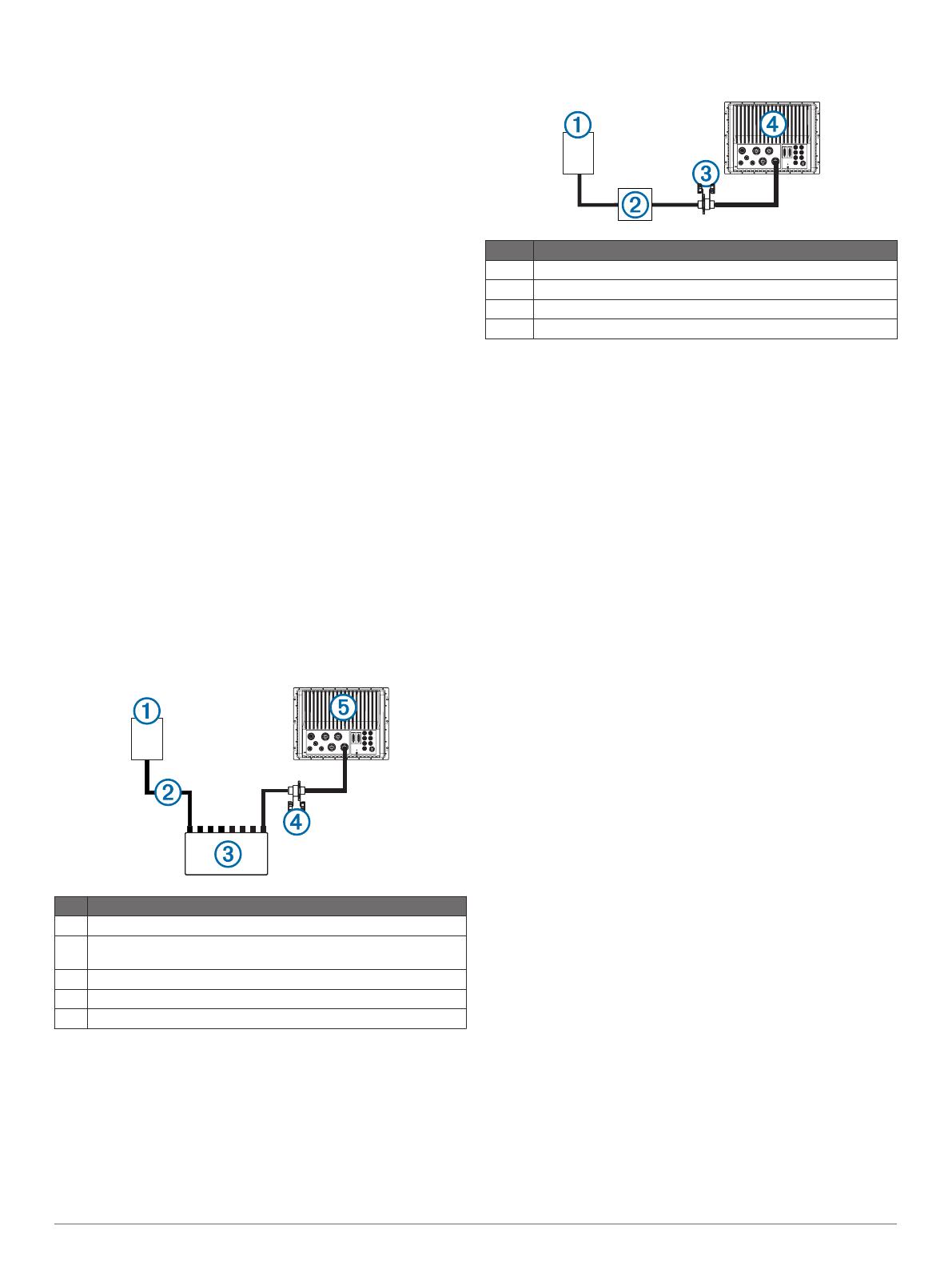
Axis Camera to Chartplotter Connection with a PoE
Switch
Item Description
À
Axis network camera
Á
PoE IEEE 802.af or IEEE 802.at, depending on the Axis camera
model
Â
PoE switch*
Ã
PoE isolator (GPN 010-10580-10)
Ä
GPSMAP chartplotter
*Not a Garmin part.
Axis Camera to Chartplotter Connection with a
Midspan PoE Injector
Item Description
À
Axis network camera
Á
Axis midspan PoE injector (or equivalent)
Â
PoE isolation coupler (GPN 010-10580-10)
Ã
GPSMAP chartplotter
Troubleshooting
Before you contact your Garmin dealer or service center, you
should perform a few simple troubleshooting steps to help
diagnose the problem.
My camera is installed but it is not in the video source
menu
Powering up the chartplotters and cameras can take several
minutes to resolve. If the camera still does not appear, you
should complete these actions.
Verify the power is connected.
Verify the circuit breakers are set properly.
Verify the Power over Ethernet (PoE) adapter power is on.
Verify the Ethernet cable is connected to your chartplotter.
Verify your routers and switches are on and functioning.
Verify the camera is working. See your camera owner's
manual for camera troubleshooting information.
Verify the camera is compatible with Garmin systems. See
Axis Network Cameras for more information on camera
compatibility.
My video displays but I cannot control the FLIR
camera
Verify the correct video input source (built-in or Axis video
encoder) is associated with the FLIR camera. See Changing
the Associated Video Input Device for a FLIR Camera for
more information.
Verify you selected the correct camera when associating the
camera with the chartpotter .
My chartplotter cannot access my Axis camera
The chartplotter uses the Axis camera's default password to
initially access the camera. When the chartplotter cannot
connect to the camera because of mismatched passwords, the
chartplotter displays a message that it cannot connect to the
camera. When this message appears, you must reset your Axis
camera password to its factory default settings. Go to
www.axis.com for instructions on resetting the camera to factory
default settings.
My chartplotter combination screen will not allow a
second built-in video source
Depending on the model, Garmin chartplotters can have up to
four built-in, or composite, video inputs. Each input can receive
a standard composite video feed from a camera. Combinations
can be configured to display multiple video sources, but only a
single video function within a combination can use a composite
video input connection to the chartplotter. To display up to four
analog video streams in one combination screen, you can add
an Axis video encoder to your network. See Multiple Network
Camera Connection for configuration details.
3
My chartplotter displays a rotated image in a
combination screen display
For cameras connected to an Axis video encoder, you must
mount all cameras at 0 degrees of rotation for proper video
display.
Garmin
®
, the Garmin logo, GMS
, and GPSMAP
®
are trademarks of Garmin Ltd. or its subsidiaries, registered in the USA and other countries. These trademarks may not be used without the express
permission of Garmin.
WiFi
®
is a registered trademark of Wi-Fi Alliance Corporation. Axis
®
is a registered trademark of Axis AB. FLIR
®
is a registered trademark of FLIR Systems, Inc. Other trademarks and trade names are those of
their respective owners.
© 2015 Garmin Ltd. or its subsidiaries www.garmin.com/support
  • Page 1 1
  • Page 2 2
  • Page 3 3
  • Page 4 4

Garmin GPSMAP 8012 MFD Reference guide

Category
Network switches
Type
Reference guide

Ask a question and I''ll find the answer in the document

Finding information in a document is now easier with AI