Page is loading ...


FFCCCC CCoommpplliiaannccee SSttaatteemmeenntt
This equipment has been tested and found to comply with the limits for a Class B digital
device, pursuant to part 15 of the FCC Rules. These limits are designed to provide
reasonable protection against harmful interference in a residential installation. This
equipment generates, uses and can radiate radio frequency energy and, if not installed
and used in accordance with the instructions, may cause harmful interference to radio
communications. However, there is no guarantee that interference will not occur in a
particular installation. If this equipment does cause harmful interference to radio or
television reception, which can be determined by turning the equipment off and on, the
user is encouraged to try to correct the interference by one or more of the following
measures:
• Reorient or relocate the receiving antenna.
• Increase the separation between the equipment and receiver.
• Connect the equipment into an outlet on a circuit different from that to which the
receiver is connected.
• Consult the dealer or an experienced radio/TV technician for help.
UUssee ooff TTrraaddeemmaarrkkss,, RReeggiisstteerreedd TTrraaddeemmaarrkkss,, aanndd
ootthheerr PPrrootteecctteedd NNaammeess aanndd SSyymmbboollss
This manual may make reference to trademarks, registered trademarks, and other
protected names and/or symbols of third-party companies not related in any way to
StarTech.com. Where they occur these references are for illustrative purposes only and
do not represent an endorsement of a product or service by StarTech.com, or an
endorsement of the product(s) to which this manual applies by the third-party company in
question. Regardless of any direct acknowledgement elsewhere in the body of this
document, StarTech.com hereby acknowledges that all trademarks, registered
trademarks, service marks, and other protected names and/or symbols contained in this
manual and related documents are the property of their respective holders.

TTaabbllee ooff CCoonntteennttss
Introduction . . . . . . . . . . . . . . . . . . . . . . . . . . . . . . . . . . . . . . . . . . . . . . . . . . .1
Features . . . . . . . . . . . . . . . . . . . . . . . . . . . . . . . . . . . . . . . . . . . . . . .1
Before You Begin . . . . . . . . . . . . . . . . . . . . . . . . . . . . . . . . . . . . . . . . . . . . .1
System Requirements . . . . . . . . . . . . . . . . . . . . . . . . . . . . . . . .1
Contents . . . . . . . . . . . . . . . . . . . . . . . . . . . . . . . . . . . . . . . . . .1
Hardware Guide . . . . . . . . . . . . . . . . . . . . . . . . . . . . . . . . . . . . . . . . . . . . . .2
Installation . . . . . . . . . . . . . . . . . . . . . . . . . . . . . . . . . . . . . . . . . . . . . . . . . . . .4
Hard drive installation . . . . . . . . . . . . . . . . . . . . . . . . . . . . . . . .4
Connecting the drive enclosure to a computer . . . . . . . . . . . . .4
ESATCASE2 . . . . . . . . . . . . . . . . . . . . . . . . . . . . . . . . . . . . . . . .4
SATCASE2U2 . . . . . . . . . . . . . . . . . . . . . . . . . . . . . . . . . . . . . . .5
Connecting the drive enclosure to a power source . . . . . . . . .5
Using the newly installed drives . . . . . . . . . . . . . . . . . . . . . . . .5
SATCASE2U2R . . . . . . . . . . . . . . . . . . . . . . . . . . . . . . . . . . . . .5
Setting up the RAID function . . . . . . . . . . . . . . . . . . . . . . . . . .5
Single mode (JBOD) . . . . . . . . . . . . . . . . . . . . . . . . . . . . . . . .6
Removing installed drives from the enclosure . . . . . . . . . . . . .6
RAID 0 (Striping) Mode . . . . . . . . . . . . . . . . . . . . . . . . . . . . . .7
Spanning Mode . . . . . . . . . . . . . . . . . . . . . . . . . . . . . . . . . . .10
Specifications . . . . . . . . . . . . . . . . . . . . . . . . . . . . . . . . . . . . . . . . . . . . . . . .3
Technical Support . . . . . . . . . . . . . . . . . . . . . . . . . . . . . . . . . . . . . . . . . . . .3
Warranty Information . . . . . . . . . . . . . . . . . . . . . . . . . . . . . . . . . . . . . . . . .3
Instruction Manual
i

IInnttrroodduuccttiioonn
FFeeaattuurreess
BBeeffoorree YYoouu BBeeggiinn
Instruction Manual
1
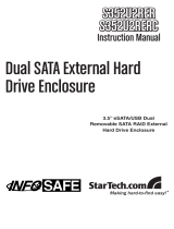
Thank for purchasing a StarTech.com Dual Hard Drive Enclosure. Featuring a sturdy
aluminum casing to protect stored drives and provide maximum heat dissipation, this
product is the perfect storage solution for RAID applications, or configurations requiring
large storage capacity.
• Hot swappable
• Driverless installation
• Sturdy aluminum casing
• Cooling fan
System Requirements
ESATCASE2:
• Pentium-based computer with available eSATA connection
• An available power receptacle
• SATA/SATA 2.0 hard drives
SATCASE2U2:
• Pentium-based computer with available USB/USB 2.0 connection
• An available power receptacle
• SATA/SATA 2.0 hard drives
SATCASE2U2R:
• Pentium-based computer with available USB/USB 2.0 connection
• An available power receptacle
• SATA/SATA 2.0 hard drives
Contents
This package should contain:
• Dual Hard Drive Enclosure (1)
• eSATA cable (2) (ESATCASE2 only)
• USB cable (2) (SATCASE2U2 and SATCASE2U2R only)
• Power adapter (1) (2pc.)
• Driver CD (For Windows 98 installation)

HHaarrddwwaarree GGuuiiddee
Front Panel
Instruction Manual
2
ESATCASE2:
1 - Locking Dial & Button
2 - Power Button (HDD 1)
3 - Power/Access LED
4- Power Button (HDD 2)
SATCASE2U2:
1 - Locking Dial & Button
2 - Power Button
3 - Power LED
4 - Activity LED (HDD 1)
5 - Activity LED (HDD 2)
SATCASE2U2R:
1 - Locking Dial & Button
2 - Power Button
3 - Power LED
4 - Activity LED (HDD 1)
5 - Activity LED (HDD 2)
6 - Striping Mode LED
7 - Spanning Mode LED
8 - Single Mode LED
1
2
3
1
2
3
4
5
1
2
3
4
5
6
7
8
4

Rear Panel
Instruction Manual
3
ESATCASE2:
1 - eSATA Ports (x2)
2 - 5V/12V Power port
SATCASE2U2R:
1 - RAID Setting Dip Switch
2 - USB Type ‘B’ Port
3 - Fan Setting Switch (High and Low
RPM Settings)
4 - 5V/12V Power port
SATCASE2U2:
1 - USB Type ‘B’ Port
2 - USB Hub (2x USB Type ‘A’)
3 - 5V/12V Power port
4 - Fan Setting Switch (High and Low
RPM Settings)
1 2
1 2 4
3
123
4

IInnssttaallllaattiioonn
Hard Drive installation
To ensure a quick and easy device installation, please read through this section carefully
before attempting to install the device.
WARNING! Hard drives, like all computer equipment, can be severely damaged by static
electricity.
1. To remove the drive tray(s) from the enclosure: Turn the locking dial to the OPEN
position (counter-clockwise). Following this, press on the button to open the locking
arm:
2. Once the locking arm is open, pull the hard drive tray out of the enclosure.
3. Place the hard drive you wish to install in the tray (label side up), aligning the
mounting holes located on the bottom of the drive with the mounting holes located on
the bottom of the tray.
4. Fasten the drive to the tray using the provided screws.
5. Insert the drive tray (containing the hard drive) into the slot made available in step 2.
Close the locking arm, until you hear a click.
6. Optional: To secure the drive tray in the enclosure, turn the locking dial to the LOCK
position (clockwise).
7. To add a second drive, follow steps 1-6, using the remaining (empty) drive tray.
Connecting the drive enclosure to a computer
ESATCASE2
Note: Please do not connect SATCASE2U2R to the host computer, until initial RAID
configuration is complete. For further instructions, please refer to SATCASE2U2R -
Setting up the RAID function.
To connect the drive enclosure to a host computer, connect one end of an eSATA cable,
to the eSATA port located on the rear panel of the drive enclosure. Connect the
remaining end of the eSATA cable to an available eSATA port on your host computer.
Instruction Manual
4
LOCK
OPEN
Press here
to open
drive bay

SATCASE2U2
To connect the drive enclosure to a host computer, insert the USB Type ‘B’ connector into
the port provided on the rear panel of the enclosure. Connect the remaining end of the
USB cable to an available USB port on your host computer.
Connecting the drive enclosure to a power source
1. The included power supply is comprised of two components. Connect the two
components, by inserting the female power plug into the main adapter.
2. Insert the male power plug into an available power receptacle.
3. Insert the remaining 7-pin, 5V/12V power connector to the power port, on the rear
panel of the enclosure.
Using the newly installed drive(s)
Once the drives have been installed in the enclosure, and the enclosure is connected to
a host computer, power the individual drives by pressing the power switch for the drive
you wish to access. This will enable the computer to use the drive, as though it were
installed directly in the computer. When the drive is powered, the POWER LED will
illuminate.
To shut down power to the drive, simply press and release the power button. Upon doing
so, the power LED will no longer be illuminated.
SATCASE2U2R
Setting up the RAID function
Once the drives have been suitably mounted in the enclosure and have been powered
on, automatic RAID configuration will begin based on the dip switch settings on the rear
panel. Note: Please power on the RAID enclosure, prior to connecting to the host
computer, to ensure that RAID has been built before connecting.
The following chart illustrates available dip switch combinations, and the resulting RAID
functions:
Once the RAID configuration has completed, connect the enclosure to the host computer
in order to format the RAID built drives. Once the drives have been formatted, they are
ready for use.
Instruction Manual
5
Mode 1 2
Strip On Off
Span Off On
Single On On
Single Off Off

Single mode (JBOD)
To configure the installed drives as Single drives, please ensure that both dip switches
are set to either the ON or OFF position (Factory default).
To format the drives:
1. Right-click on My Computer, and left-click on Manage.
2. Double-click on Storage, then double-click on Disk Management to view the attached
drives, which will appear as follows. Right-click on each drive, and format accordingly:
Removing installed drives from the enclosure
Please note: Removing a hard drive from the enclosure while the drive is busy, can
result in lost data. To remove one of the drives, please open the Safely Remove
Hardware icon located in the taskbar, which will launch the following screen. Highlight
the drive you wish to remove, and click on the Stop button:
Instruction Manual
6

Once the drive has been stopped:
1. Turn the locking dial covering the drive you wish to remove, to the OPEN position.
2. Press the lock button until the locking arm swings open.
3. Gently pull the drive out of the enclosure.
Striping (Strip) Mode
Warning: Please backup any original data prior to building your RAID configuration, as
all data wil be lost due to format.
To configure your drives for RAID 0, please set the dip switches accordingly, based on
the chart on page 5. Turn on the enclosure for the RAID to automatically be built.
Once the RAID has been built, turn off both disks using the main power button on the
enclosure. Once the drives have been powered down, connect the enclosure to the host
computer using the USB cable provided. Following connection, restore power to the
enclosure and format the drives,
1. Right-click on My Computer
2. Left-click on Manage.
3. Double-click on Storage, then double-click on Disk Management to view the attached
drives, which will appear as follows. Right-click on each drive, and format accordingly:
RAID 0 rebuilds both hard drives into a single, double-sized drive. With this type of RAID
configuration, if one drive fails, the entire RAID build will crash. However, as data storage
is spread over both hard disks, performance is much faster than on a standard, single
disk configuration.
Please note: For optimum performance, it is strongly recommended that two identical
hard drives are used. If the two drives are not the same size, RAID can only be built to a
Instruction Manual
7
Note: RAID has been
configured to include both
drives as a single drive.
Please remove any
existing partitions.

capacity equal to twice the size of the smaller drive (i.e. if a 200GB hard and 100 GB
hard drive are used, the total capacity of the RAID build will equal 200GB).
To delete any existing partitions (from within Disk Management), right-click on the drive
you wish to modify, and select Delete Partition:
Note: all data will be lost from the partitioned space, upon deletion:
Instruction Manual
8
Click ‘Yes’ to combine both
drives into a single, larger
drive.


Once the RAID set has been built, it should appear as follows, in Disk Management.
Note that the two individual drives have been combined:
Spanning (SPAN) Mode
Spanning Mode offers no fault tolerance, and no redundancy. If either hard drive fails,
the Span function will fail. Span HDD capacity is equivalent to the total of the two hard
disks.
To select JBOD, please set dip switch 1 to the OFF position, and switch 2 to the ON
position:
Instruction Manual
10
Set the HDD size and partition type, then Click Next:
Please note: Changing dip
switch settings while RAID
is being built, or is working
can result in data
loss/damage.

SSppeecciiffiiccaattiioonnss
Instruction Manual
11
Regulatory Certifications CE, ROHS
Data Transfer Rate (Max.) 480Mbps
Product Dimensions 200x149x70mm
(7.9 x 5.9 x 2.8”)
Connectors
USB Type ‘B’ Port (1)
USB Hub (2x USB Type ‘A’)
5V/12V Power port
Interface SATA /150, SATA II /300
SATCASE2U2
Regulatory Certifications CE, ROHS
Data Transfer Rate (Max.) SATA /150: 150Mbps
SATA /300: 300Mbps
Chipset Oxford 921DS
Product Dimension 200x149x70mm
(7.9 x 5.9 x 2.8”)
Connectors eSATA (2)
5V/12V Power port (1)
Interface SATA /150, SATA II /300
Regulatory Certifications CE, ROHS
Data Transfer Rate (Max.) 480Mbps
Chipset Oxford 921DS
Product Dimensions 200x149x70mm
(7.9 x 5.9 x 2.8”)
Connectors USB Type ‘B’ Port (1)
5V/12V Power port
Interface SATA /150, SATA II /300
ESATCASE2
SATCASE2U2R

Instruction Manual
12
TTeecchhnniiccaall SSuuppppoorrtt
StarTech.com’s lifetime technical support is an integral part of our commitment to
provide industry-leading solutions. If you ever need help with your product, visit
www.startech.com/support and access our comprehensive selection of online tools,
documentation, and downloads.
WWaarrrraannttyy IInnffoorrmmaattiioonn
This product is backed by a one-year warranty. In addition, StarTech.com warrants its
products against defects in materials and workmanship for the periods noted, following
the initial date of purchase. During this period, the products may be returned for repair,
or replacement with equivalent products at our discretion. The warranty covers parts
and labor costs only. StarTech.com does not warrant its products from defects or
damages arising from misuse, abuse, alteration, or normal wear and tear.
Limitation of Liability
In no event shall the liability of StarTech.com Ltd. and StarTech.com USA LLP (or their
officers, directors, employees or agents) for any damages (whether direct or indirect,
special, punitive, incidental, consequential, or otherwise), loss of profits, loss of
business, or any pecuniary loss, arising out of or related to the use of the product
exceed the actual price paid for the product. Some states do not allow the exclusion or
limitation of incidental or consequential damages. If such laws apply, the limitations or
exclusions contained in this statement may not apply to you.

Revised: 15 March 2007 (Rev. A)
AAbboouutt SSttaarrTTeecchh..ccoomm
StarTech.com is “The Professionals’ Source for Hard-to-Find Computer
Parts”. Since 1985, we have been providing IT professionals with the
quality products they need to complete their solutions. We offer an
unmatched selection of computer parts, cables, server management
solutions and A/V products and serve a worldwide market through our
locations in the United States, Canada, the United Kingdom and Taiwan.
Visit www.startech.com for complete information about all our products
and to access exclusive interactive tools such as the Parts Finder and the
KVM Reference Guide. StarTech.com makes it easy to complete almost
any IT solution. Find out for yourself why our products lead the industry in
performance, support, and value.
/