Page is loading ...

Rev:
Page:
E.C.O. No:
CUSTOMER SERVICE PHONE: 1-800-426-8562
3480-062 1 of 6 6100-0123
Part No:
Lateral Files & Accessories
Installation Instructions
BE_HOLD™
Scale 1 : 1
0 11/2
1/4 1/4
Tools Required
Electrical Tape
#2
S194
CushionTop
Counter Weight(s)
Drawer Dividers Ganging Kit
Drawer organizers
Panel Bracket
AA1
C
S-3
F
E
D
S231
S-43
S-3
J
S229
1/8” Drill 9/32” Drill

Rev:
Page:
E.C.O. No:
CUSTOMER SERVICE PHONE: 1-800-426-8562
2 of 6 6100-0123
Part No:
2 3
B1
RIGHT HAND
APPLICATION
LEFT HAND
APPLICATION
1
1/4”
1/8”
Drill 1
2
#10 x 5/8" Pan Head Screw
(S-3)
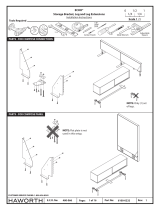
PANEL BRACKET INSTALLATION
C
B
B
B
B
B3
B
S-3
1
2
3480-062

Rev:
Page:
E.C.O. No:
CUSTOMER SERVICE PHONE: 1-800-426-8562
3 of 6 6100-0123
Part No:
4 5
1-1/8”
2H
1.5H
3/4”
TOP INSTALLATION
CC
2
1
B1
B
3/4”
A
S194
B
#10 x 1-1/8"" Pan Head Screw
(S194)
A2
3480-062

B
S273 S274
A1
3/4”
1-3/16” 1-3/16”
3/4”
(S273)
1/4-20 x 1-3/4" Pan Head Screw
(S274)
1/4-20 x 2-1/4" Pan Head Screw
NOTE: If required, go to local
hardware store and purchase
simular screws (S274).
NOTE: Screw (S273) is used with
3/4” top. (provided)
NOTE: Screw (S274) is used with
1-3/16” top. (not provided)
With Top
With Top
CUSHION INSTALLATION
OR
Rev:
Page:
E.C.O. No:
CUSTOMER SERVICE PHONE: 1-800-426-8562
4 of 6 6100-0123
Part No:
1
2
B
NOTE: Use locating
holes as shown and drill
through top (A).
9/32” Drill
3480-062

Rev:
Page:
E.C.O. No:
CUSTOMER SERVICE PHONE: 1-800-426-8562
4 of 6 6100-0123
Part No:
1
2
GANGING INSTALLATION
2
B
B2
#10 x 5/8" Pan Head Screw
(S-3)
#10-16 x 1-1/4"" Pan Head Screw
(S-43)
3
1
2
3
LIFT
ROTATE
PLACE
B
J
2”
S-43
1/4”
1/8”
Drill
1
3480-062

Rev:
Page:
E.C.O. No:
CUSTOMER SERVICE PHONE: 1-800-426-8562
5 of 6 6100-0123
Part No:
B
DRAWER ORGANZER INSTALLATION DRAWER DIVIDER INSTALLATION
B
COUNTERWEIGHT INSTALLATION
24”, 30”, 36“, 42”
24” DEPTH 16” DEPTH
16”
B
B
B
MAKE SURE TO
INSTALL THE CORRECT
COUNTERWEIGHT
WITH CABINET
IMPORTANT!
42”
C
L
36”
C
L
36”
C
L
30”
C
L
24”
C
L
E
F
S231
D
#10 x 1-1/4” Rnd Washer Head Screw
(S231)
3480-062

Rev:
Page:
E.C.O. No:
CUSTOMER SERVICE PHONE: 1-800-426-8562
6 of 6 6100-0123
Part No:
G
G
DOOR HINGE ADJUSTMENTDOOR INSTALLATION/REMOVAL
2
1
1
2
3
1
2
3
4
3
CK-3 CK-3
HW-SERIES
X
HW-SERIES
Install lock plug (HW-SERIES)
NOTE: Position cam to
unlocked (12:00 o’clock
position.
NOTE: It may be
necessary to rotate cam
until lock plug engages.
NOTE: Hold the lock
plug (HW-SERIES) in
place with thumb
while removing the
control key (CK-3).
Remove round key (CK-3)
and insert square key (X)
X
OPTIONAL LOCK PLUG INSTALLATION
1
2
CK-3
AG
CK-1
HW-SERIES
Remove shipping plug
(AG) with round key (CK-1)
Replace square key (X) with round key (CK-3)
1
1
2
2
PULL INSTALLATION
1
2
(S233)
M4 x 25mm Pan Head Screw
B9
B9
S233
S233
K
5/32"
K
3480-062
DRAWER LOCK BAR ADJUSTMENT
/


