Page is loading ...

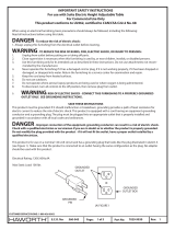
GROUNDED
OUTLET
GROUNDED
OUTLET BOX
GROUNDED
PIN
(A) FIGURE 1
1 of 12 6100-0060 Rev:
Part No:
Page:
E.C.O. No:
CUSTOMER SERVICE PHONE: 1-800-426-8562
1245-602
Maximum functional load: 175 lbs
Power Base Electrical Rating: 208Y/120V, 120/240V or 120V 60Hz, 20A
Electrical Rating: 120V, 60Hz, 7A
IMPORTANT SAFETY INSTRUCTIONS
For use with HOP Electric Height Adjustable 120 Degree Benches
For Commercial Use Only
This product conforms to UL Std. 962 & 1286 and is certied to
CSA Std. C22.2 No. #68 & #203
When using an electrical furnishing, basic precautions should always be followed, including the following:
Read all instructions before using this table.
DANGER - To reduce the risk of electric shock:
1. Always unplug this furnishing from the electrical outlet before cleaning.
WARNING - TO REDUCE THE RISK OF BURNS, FIRE, ELECTRIC SHOCK, OR INJURY TO PERSONS:
1. Unplug from outlet before putting on or taking o parts.
2. Close supervision is necessary when this furnishing is used by, or near children, invalids, or disabled persons.
3. Use this furnishing only for its intended use as described in these instructions. Do not use attachments not recom-
mended by the manufacturer.
4. Never operate this furnishing if it has a damaged cord or plug, if it is not working properly, if it has been dropped or
damaged, or dropped into water. Return the furnishing to a service center for examination and repair.
5. Keep the cord away from heated surfaces.
6. Do not use outdoors.
7. Do not operate where aerosol (spray) products are being used or where oxygen is being administered.
8. To disconnect, turn all controls to the o position, then remove plug from outlet.
9. WARNING: RISK OF ELECTRIC SHOCK, USE ONLY SJT TYPE 18 AWG CORD AT THE APPLIANCE INLET -
CONNECT THIS FURNISHING TO A PROPERLY GROUNDED OUTLET ONLY. SEE GROUNDING INSTRUCTIONS.
SAVE THESE INSTRUCTIONS
This product must be grounded. If it should malfunction or breakdown, grounding provides a path of least resistance for
electric current to reduce the risk of electric shock. This product is equipped with a cord having an equipment-grounding
conductor and a grounding plug. The plug must be plugged into an appropriate outlet that is properly installed and
grounded in accordance with all local codes and ordinances.
DANGER - Improper connection of the equipment-grounding conductor can result in a risk of electric shock.
Check with a qualied electrician or serviceman if you are in doubt as to whether the product is properly grounded.
Do not modify the plug provided with the product - if it will not t the outlet, have a proper outlet installed by a
qualied electrician.
This product is for use on a nominal 120-volt circuit and has a grounding plug that looks like the plug illustrated in sketch A
(see Figure 1). Make sure that the product is connected to an outlet having the same conguration as the plug. No adapter
should be used with this product.

S-94
S-94
S-1
C
S-1
S120
S120
S-94
Frame
Beam
S120
G
PDA
Bracket
G
Communication
Bracket
245-602 2 of 12 6100-0060 1
Rev:
Part No:
Page:
E.C.O. No:
Tools Required
2mm
2.5mm
4mm
5mm & 6mm
120˚ Adjustable Tables
Installation Instructions
HOP®
FOR ELECTRIC & CRANK TABLES
CUSTOMER SERVICE PHONE: 1-800-426-8562
D
Frame
Cover P
S118
0
0
K
L
M
H
B
S-81
NE
D
N
Q
A
A1
#2
(S-94)
Socket Cap M6 X 10mm
(S118)
M6 x 30mm Socket Head Cap Screw
(S-81)
Flat Head M6 X 12mm
#10 x 3/8" Screw
(S120)
#10 x 1" Pan Head Screw
(S-1)
#10 x 1/4" Screw
(S121)
T
Programmable
Switch
OR
FOR ELECTRIC TABLES
S-1
UControl Module
S118
M
Plastic
Button
Center
Rail
Angle
Bracket
Column
Worksurface
Bracket
Worksurface
Bracket
Frame
Rail
F
G
J
S
V
Scale 1 : 1
011/2
1/4 1/4

245-602 3 of 12 6100-0060 1
Rev:
Part No:
Page:
E.C.O. No:
CUSTOMER SERVICE PHONE: 1-800-426-8562
1
2
A
A1
A
B
C
S-94
A
(S-94)
Socket Cap M6 X 10mm
(S118)
M6 x 30mm Socket Head Cap Screw
MAKE SURE
HOLES ARE
ON TOP!
IMPORTANT
C

245-602 4 of 12 6100-0060 1
Rev:
Part No:
Page:
E.C.O. No:
CUSTOMER SERVICE PHONE: 1-800-426-8562
3 4
D
(S-94)
Socket Cap M6 X 10mm
S-94
A
D
F
E
G
5(S118)
M6 x 30mm Socket Head Cap Screw
S120
S120
E

245-602 5 of 12 6100-0060 1
Rev:
Part No:
Page:
E.C.O. No:
CUSTOMER SERVICE PHONE: 1-800-426-8562
C1
C1
Ordered Separately
as power retrot kit
6
7
FOR POWER
A) All interconnected electrical
systems shall terminate with
an oce furnishings electrical
system.
B) All interconnected electrical
systems shall not have an
interconnection such that an
oce furnishings system is
rst and then followed by a
manufacturing wiring system.
C) All interconnected electrical
systems shall not alternate
between oce furnishing and
manufacturing wiring systems.
C3
C1
C1
BASE FEED
C4
C5
RECEPTACLE
JUMPER
NOTE: Install all jumpers (C3),
basefeeds (C4), and receptacle’s (C5)
before installing cable troughs (E).
1
2
G
C1
S124
#10 x 3/8" Screw
(S120)
#10-24 x 3/8" Hex
Flange Head Screw
(S124)
S120
H1
H2

245-602 6 of 12 6100-0060 1
Rev:
Part No:
Page:
E.C.O. No:
CUSTOMER SERVICE PHONE: 1-800-426-8562
9
H
H
S120
S121
J
8
#10 x 3/8" Screw
(S120)
#10 x 1/4" Screw
(S121)
K

10
245-602 7 of 12 6100-0060 1
Rev:
Part No:
Page:
E.C.O. No:
CUSTOMER SERVICE PHONE: 1-800-426-8562
(S-94)
Socket Cap M6 X 10mm
11
S-94
S-94
S-94
(S-94)
Socket Cap M6 X 10mm
S-94
OR
REFER TO SCREEN INSTRUCTIONS
Part Number: 6100-0062
M
L
N
N
N
B
K

245-602 8 of 12 6100-0060 1
Rev:
Part No:
Page:
E.C.O. No:
CUSTOMER SERVICE PHONE: 1-800-426-8562
12 (S-94)
Socket Cap M6 X 10mm
S94
(S-81)
Flat Head M6 X 12mm
S81
K
0

245-602 9 of 12 6100-0060 1
Rev:
Part No:
Page:
E.C.O. No:
CUSTOMER SERVICE PHONE: 1-800-426-8562
P
Q
C
S94
M
13 (S-94)
Socket Cap M6 X 10mm

245-602 10 of 12 6100-0060 1
Rev:
Part No:
Page:
E.C.O. No:
CUSTOMER SERVICE PHONE: 1-800-426-8562
14
S1
R
#10 x 1" Pan Head Screw
(S-1)

S
S-1
2
3
T
S
OR
U
V
1
16
17
FOR ELECTRIC TABLES
Rev:
Part No:
Page:
E.C.O. No:
CUSTOMER SERVICE PHONE: 1-800-426-8562
11 of 12 6100-0060 1
245-602
#10 x 1" Pan Head Screw
(S-1)
R
W
S-1

1 2 3
4
FOR ELECTRIC TABLES
123
S
1 423
S
S
123
PRESET SWITCH INSTRUCTIONS
OR
Postion top to desired height Press "S" button Press & hold desired button
Repeat for each setting
Rev:
Part No:
Page:
E.C.O. No:
CUSTOMER SERVICE PHONE: 1-800-426-8562
12 of 12 6100-0060
Initial Calibration
After assembly all electric tables must be calibrated to insure smooth and trouble free movement.
1. Lower the table to the lowest height by pressing the down arrow on the switch.
2. Continue to press the down arrow for 5 to 10 seconds.
NOTE: The table will readjust itself if needed.
Saving a height position with the preset switch
1. Position the top to the desired height
2. Press the S button
3. Within 5 seconds press the desired number key (1-4) until a double click is heard.
NOTE: The readout will show for example S(number) until the double click is heard and then the height readout will return
Changing from inches to centimeters
The table ships set to read in inch increments but can be changed on site to read in centimeters.
Press the 1, 2 and up arrow buttons simultaneously
Use the up and down arrow keys until the readout shows S 5
Press the S button to complete
Use the same procedure to switch back to inches
Moving to a preset height
Press the appropriate number button.
Continue to press the button until the saved position is reached.
Follow-up Calibration
1. Inform the user that the table should be recalibrated once every month by following the instructions above.
2. The table should also be recalibrated if jerky or uneven movement is noted.
1245-602
/


