Page is loading ...

The dual-function acoustic switch stands out
compared to other devices of this type with the
possibility to select control method. It is possible
to control the device by single or double clap. The
circuit is powered by a safe 12 V voltage, and the
output can be connected directly to the LED strip
or 12 V bulb. The device is ideal as a remote light
switch or impressive controller of equipment.
Characteristics
• response to single or double clap
• reduced to a minimum susceptibility to other sounds
and thus accidental triggering
• LED indication of operating status
• sensitivity adjustment
• output: 8 A relay
• power supply: 12 VDC
• PCB size: 34×76 mm
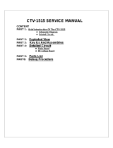
Schematic diagram of the circuit is shown in
Figure 1. Operation of the circuit is controlled by
an ATTINY25 microcontroller clocked by an
internal clock signal. This switch must be supplied
with a DC voltage of 12 V. It can be any power
supply with current capacity corresponding to the
attached load. Diode D1 protects the circuit from
incorrect polarity of the input voltage. Stabiliser
U1 provides 5 V and components C7-C10 ensure
adequate filtering of this voltage. The signal from
the microphone goes to the preamplifier, based
on the TL072 chip. The amplifier frequency
response has been reduced to the lower part of
the audible band. Potentiometer PR1 is used to
adjust the sensitivity of the circuit, while the
MODE jumper allows you to select the control
method of the switch. When set in position 'I', it
will configure the device for single clap operation,
while position 'II' will enable control by double
clap. Other similar sounds, e.g., a loud knock or
even a dog barking, can also be interpreted by the
system and trigger the relay. Although the
proposed solution has succeeded in significantly
reducing the system's susceptibility to sounds
Circuit description
12V Clap Switch for one or two claps
AVT 3144
Pobierz PDF
1
kits
ASSEMBLY DIFFICULTY

Fig. 1. Schematic diagram
Mounting and start-up
from environment, an accidental tripping of the
switch cannot be ruled out. A relay with a contact
rating of 8 A / 230 VAC was used as the executive
circuit. In spite of the considerable load capacity
of the relay, when controlling high power, pay
attention to the load on the board paths. To
improve their load capacity you can tin or solder
the copper wire on them. LED1 acts as device
status indicator. While, the connector SW allows
the attachment of an additional button, which will
make it possible to directly switch the relay
without clapping.
Fig. 2 Arrangement of components on the PCB.
Start mounting the circuit from soldering resistors
to the board and other components with small
size, and end up mounting the sockets, electrolytic
capacitors, screw connectors and relay. Once
mounted, preset potentiometer PR1 in the middle
position. To the CON2 connector you can connect
any 12V receiver, and to the MIC connector an
electret microphone, maintaining appropriate
polarity. Finally, connect the power supply to
CON1 connector. Properly assembled circuit works
immediately, only needs to be experimented to
adjust its sensitivity and select the most optimal
microphone orientation. Operation of the switch
in "I" mode does not require any special
comment, the device reacts to single claps, where
each successive trigger changes the state of the
relay to the opposite. In mode "II" the device only
reacts to double claps, consecutive, at specified
intervals. The second clap must be between 1s
and 2s after the first clap. The first clap causes the
LED to flash which, after approximately 1s will go
on to signal that it is the right time for another
clap.
To prevent accidental activation when the system
detects an incorrect sequence of sounds, its
operation will be locked for a few seconds. After
2,4k 1M
1M 1M
100nF
100nF
1nF 100nF
1nF
470k
ATTINY25
TL062P
TL062P
1M
1M
1M 1M
100nF
220uF 220uF
100nF 100nF
1N4007
2,4k
5k
BC548
2,4k
220R
2,4k
220uF
78L05
1N4007
MIC+
MIC-
SW
CON1
CON2
R1 R2
R3 R5
C1
C2
C3 C4
C6
R6
(ADC2)PB4 3
(ADC3)PB3 2
(RESET)PB5 1
(SCK)PB2 7
(MISO)PB1 6
(MOSI)PB0 5
VCC
8
GND
4
U3
2
3
1
U2A
6
5
7
U2B
R7
R8
R9
84
R10
C5
C7 C8
C9 C10
D2
R12 LED1
PR1
T1
R13
R11
R4
C11
GND
VI
3
2
VO 1
U1
2 1
PK1
PK1
1
2
3
TRYB
D1
VDD
VDD
VDD
VDD
VDD
VDD
GND
GND
GND
GND
GND
GND
GND
SIG
SIG
LVL
LVL
LED
LED
CNF
CNF
REL
REL
+
+
+
2

Start mounting from soldering the components onto the board in order of size from
smallest to largest. When mounting components marked with an exclamation mark, pay
attention to their polarity. Photographs of the mounted kit may be helpful. To access the high-
resolution images as links, download the PDF.
!
List of components
Resistors:
R1, R4, R12, R13:..................2,4 kΩ
R2, R3, R5, R7-R10: .............1 MΩ
R6:.............................................470 kΩ
R11:...........................................220 Ω
PR1: ..........................................potentiometer 5 kΩ
Capacitors:
C1, C2, C4, C5, C9, C10: .....100 nF
C3, C6: .....................................1 nF
C7, C8, C11:............................220 uF !
Semiconductors:
D1, D2:.....................................1N4007 !
LED1: ........................................LED !
T1: .............................................any NPN e.g. BC547 !
U1:.............................................78L05 !
U2:.............................................TL062 !
U3:.............................................ATTINY25 !
Other:
PK1: ..........................................relay 5 V
CON1, CON2, MIC, SW:.....screw connectors
MODE: .....................................goldpin 1×3 + JUMPER
several trials, the control of the switch will become
intuitive, and catching the right moment for a clap
will be no problem.
The switch has additional functionality which
consists in switching the relay after energizing. As
a result, if the system is incorporated into existing
lighting installation behind the main switch, then
when it is switched on, the lighting will go on
immediately and, after switching off the main
switch, it will turn off. This feature does not affect
in any way the system, but gives additional
possibility of switching the lighting on and off
using a clap of the hands. An example of such use
of the switch is shown in Figure 3.
12V DC
SENSITIVITY
ADJUSTMENT
Rys. 3.
3
Pobierz PDF

Notes
4
AVT SPV reserves the right to make changes without prior notice.Installation and connection of the appliance not in accordance with the instructions, unauthorised modification of
components and any structural alterations may cause damage to the appliance and endanger persons using it. In such a case, the manufacturer and its authorised representatives shall
not be liable for any damage arising directly or indirectly from the use or malfunction of the product.
The self-assembly kits are intended for educational and demonstration purposes only. They are not intended for use in commercial applications. If they are used in such applications, the
purchaser assumes all responsibility for ensuring compliance with all regulations
This symbol means do not dispose of your
product with your other household waste.
Instead, you should protect human health
and the environment by handing over your
waste equipment to a designated collection
point for the recycling of waste electrical
and electronic equipment.
Leszczynowa 11 Street,
03-197 Warsaw, Poland
https://sklep.avt.pl/
AVT SPV Sp. z o.o.
kits
1/4