AVT EDU644 User manual

Type
User manual

AVT EDU644 is a unique educational soldering kit that allows you to build your own colorophone, a device that converts sound into a mesmerizing light show. With its integrated microphone, the colorophone reacts to the surrounding sounds, displaying a variety of colors and patterns in sync with the music or audio. It features adjustable sensitivity, allowing you to customize its response to different sound levels. Perfect for parties, audiophiles, and anyone who wants to explore the visual representation of sound.

AVT EDU644 is a unique educational soldering kit that allows you to build your own colorophone, a device that converts sound into a mesmerizing light show. With its integrated microphone, the colorophone reacts to the surrounding sounds, displaying a variety of colors and patterns in sync with the music or audio. It features adjustable sensitivity, allowing you to customize its response to different sound levels. Perfect for parties, audiophiles, and anyone who wants to explore the visual representation of sound.

LED Colorophone
Educational soldering kit
ZOOM
AVT EDU644
1
However, we know that not everyone has as
sophisticated a sense of humour as we do, so we also
include the product description below if necessary.
It has not been known for a long time that the alarm
alerts, the painter paints and the resistor puts up
resistance. So, if one day someone were to ask you
what the Colorophon actually does, the answer is
childishly simple - the Colorophon colours :)
The colorophone catches the surrounding sounds and,
depending on their tone, frequency and intensity,
lights up in a quite different way for each sound. The
application of this smart device is much more
interesting than it might seem.
It is not only useful for partygoers, musicians and
audiophiles - there are many more options. From rave
parties (or indeed all parties), to signalling to children
that they are too loud, even to checking who is
snoring in what key. Referring to the above
description, virtually countless other possibilities for
the use of our Colorophone come to mind.
Of course, the most essential function of our EDU kit
is the opportunity to develop passion and soldering
skills.
board size: 149 ×79 mm
Specifications
light effect produced to the rhythm of the music
integrated micron - no direct connection to sound
source required
responds to low, medium and high tones
light source - LEDs in three colours
stepless sensitivity adjustment
supply: 12 VDC /200 mA (2.1/5.5)
kits
PDF
DOWNLOAD
2
LM358N
LM358N
1k
10k
100k
1k
10k
100k
10uF
10uF
100nF
22nF
100nF
BC337
BC337
2,2uF
10k
10k
10k
4,7uF
1N4148
1N4148
1uF
1k
220nF
1N4148
100
BC337
1k
47nF 1N4148
10
10
10
10
BC337
1k 1nF
1N4148
100
100
100
100
GND
GND
GND
100k
GND
100k
47nF
GND 0
0
0
2
3
1
IC1A
6
5
7
IC1B
R1
R2
R3
R4
R5
R6
C3
C4
C5
C6
C7
T1
T2
C10
R7
R8
R9
C11
D2
D3
C12
R10
C13
D4
R16 LED7 LED8
T3
R11
C15 D5
R17 LED9 LED10
R18 LED11 LED12
R19 LED13 LED14
R20 LED15 LED16
T4
R12 C16
D6
R21 LED17 LED18
R22 LED19 LED20
R23 LED21 LED22
R24 LED23 LED24
PR1
R25
C14
8
4R26
R27 R28
+
+
+
+
100uF 100uF 100nF 100nF
ON/OFF 100
100
100
1N5819
0
C1 C2 C8 C9
SW1
R13 LED1 LED2
R14 LED3 LED4
R15 LED5 LED6
D1
R29
+
+
1
MIC
2
1
2
3
J1
+
Fig. 1 Schematic diagram
Fig. 2. Arrangement of components on the PCB
3
Recommended mounting order:Recommended mounting order:Recommended mounting order:
C1-C4
C10
...
C12
longer
leg
1
IC1
marker
marker
D1:......................................1N5819 !
C1, C2:...............................100 μF !
C12:....................................1 μF !
C5, C7-C9:........................100 nF (can be labelled 104)
MIC: ..................................microphone
C16:....................................1 nF (can be labelled 102)
C10:....................................2.2 μF !
R3, R6, R25: .....................100 kΩ (brown-black-yellow-gold)
R13-R16, R21-R24: .......100 Ω (brown-black-brown-gold)
C11:....................................4.7 μF !
C13:....................................220 nF (can be labelled 224)
R17-R20:...........................10 Ω (brown-black-black-gold)
C3, C4:...............................10 μF !
PR1: ...................................100kΩ potentiometer + adjustment shaft
C6: .....................................22 nF (can be labelled 223)
R1, R4, R10-R12:............1 kΩ (brown-black-red-gold)
T1-T4: ...............................BC337 ! (or similar)
IC1: ....................................LM358 chip + base !
D2-D6:...............................1N4148 !
C14, C15:..........................47 nF (can be labelled 473)
R2, R5, R7-R9:.................10 kΩ (brown-black-orange-gold)
R26-R29:...........................0 Ω (black)
LED9-LED16: ...................YELLOW LED !
LED1-LED8:......................RED LED !
J1: .......................................power socket
SW1: ..................................on/off switch
LED17-LED24: ................BLUE LED !
D2
...
D6
A
K
markermarkermarker
T1
...
T4
LED1
...
LED24
C
notch
A
A
C
D1
markermarkermarker
largest. When mounting
components marked with an
exclamation mark, pay attention
to their polarity.
Start assembly by soldering
components into the board,
in the order of their size, from
the smallest to the
To access high-resolution
images, download the PDF.
!
MIC
minus
on the casing
Components received in the kit, may differ in appearance from those shown in the photograph. Despite this, they
have the same parameters, and their appearance will not affect their operation in the unit.
!
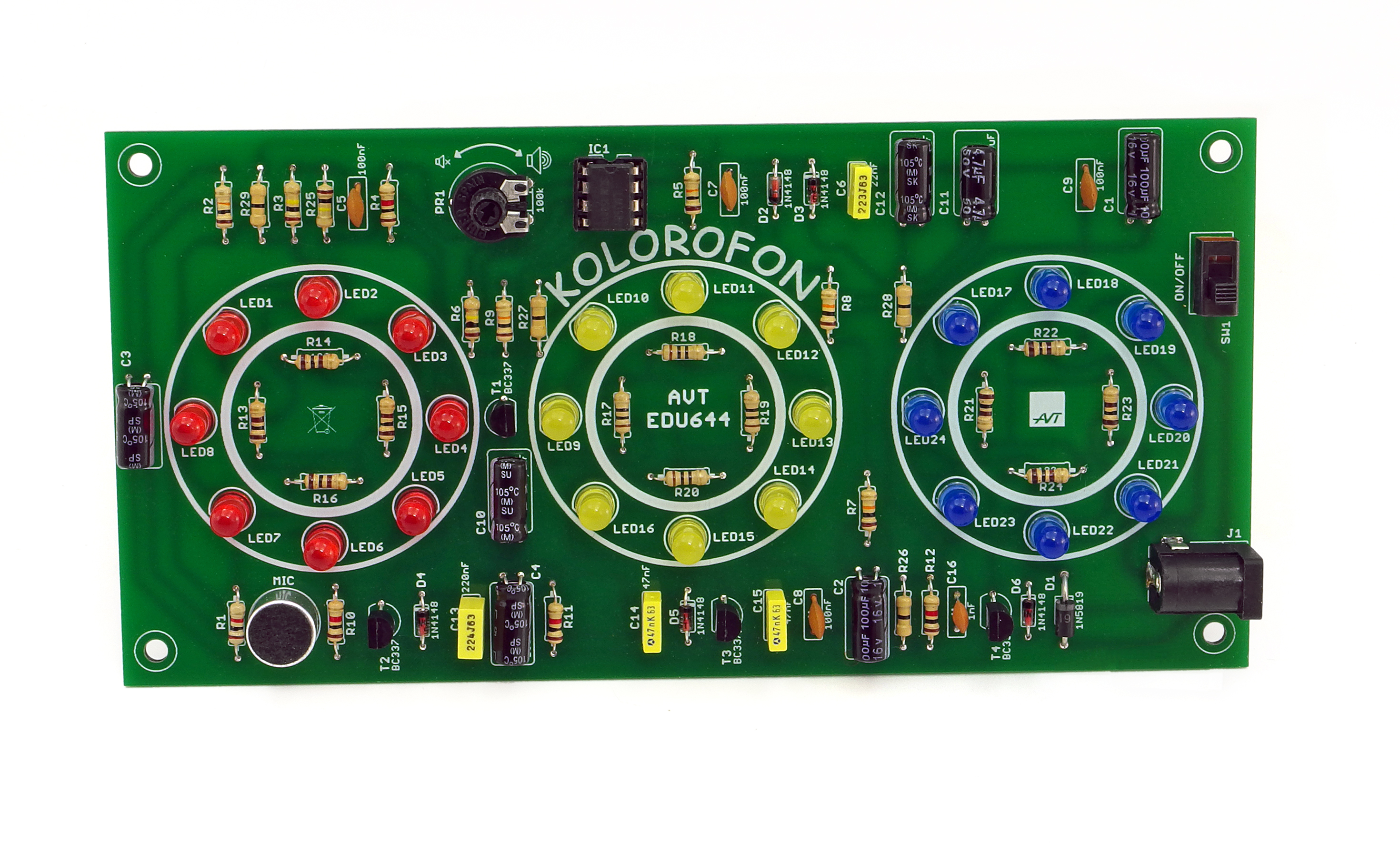
Figure 2 shows the layout of the components on the
PCB.
Solder the components sequentially onto the board,
starting with the smallest ones. Once the system has
been mounted, very carefully check correctness of
installation. Check that the components have not
been soldered in the wrong direction or in the wrong
places and that no soldering points have been short-
circuited during soldering. The sensitivity of the
Colorophone can be adjusted using potentiometer
PR1.
Mounting and start-up
bevelled
edge
PDF
DOWNLOAD
ZOOM
4
Mounting instructions
1
1
2
2
3
3
4
4
Once the cone has formed, remove the 'tin’
leg/end of the component just outside the
soldering field
Use the tip of a hot soldering iron to touch the
Then apply the "tin"/spoil
The entire process should take 2-3 seconds
The prerequisites for the formation of a correct
joined, the presence of flux in the binder, a
Too low a temperature or amount of binder, as
well as impurities, can lead to "cold solders", i.e.
the binder and the flux contained in it do not wet
the surfaces to be joined and an impermanent
solder is formed, which will oxidise over time, a
break will occur and the device will cease to
function
the correct amount of binder.
solder are the cleanliness of the surfaces to be
Too much binder will cause a bead to form or two
adjacent solder points to join.
and then the soldering iron
sufficiently high temperature (320-360°C) and
AVT SPV reserves the right to make changes without prior notice.Installation and connection of the appliance not in accordance with the instructions, unauthorised modification of
components and any structural alterations may cause damage to the appliance and endanger persons using it. In such a case, the manufacturer and its authorised representatives shall
not be liable for any damage arising directly or indirectly from the use or malfunction of the product.
The self-assembly kits are intended for educational and demonstration purposes only. They are not intended for use in commercial applications. If they are used in such applications, the
purchaser assumes all responsibility for ensuring compliance with all regulations
This symbol means do not dispose of your
product with your other household waste.
Instead, you should protect human health
and the environment by handing over your
waste equipment to a designated collection
point for the recycling of waste electrical
and electronic equipment.
Leszczynowa 11 Street,
03-197 Warsaw, Poland
https://sklep.avt.pl/
AVT SPV Sp. z o.o.
kits
  • Page 1 1
  • Page 2 2
  • Page 3 3
  • Page 4 4

AVT EDU644 User manual

Type
User manual

AVT EDU644 is a unique educational soldering kit that allows you to build your own colorophone, a device that converts sound into a mesmerizing light show. With its integrated microphone, the colorophone reacts to the surrounding sounds, displaying a variety of colors and patterns in sync with the music or audio. It features adjustable sensitivity, allowing you to customize its response to different sound levels. Perfect for parties, audiophiles, and anyone who wants to explore the visual representation of sound.

Ask a question and I''ll find the answer in the document

Finding information in a document is now easier with AI