Page is loading ...

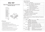
DG-850TH
Touch Panel Keypad Operation Manual
Specifications
12VDC
Active: 90mA/12VDC, Standby: 70mA/12VDC
LED Indicators & Keypad Sounds
LED
A. Operation Instructions
Copyright All Rights Reserved. P-MU-DG-850TH Published:2019.04.12
Copyright All Rights Reserved. P-MU-DG-850TH Published:2019.04.12
a - Enter Programming Mode
Enter the master code twice (Default value: “1234” or “12345) to enter programming mode (2 beeps)
Note: 1. After 60 seconds if no data entered, the keypad will automatically exit the programming mode.
2. The controller will be locked for 60 seconds upon 30 consecutive wrong master code entries.
b - Add New PINs
1. Enter programming mode.
2. Enter slot position 01~ 21.
3. Enter the PINs (1 beep).
4. Repeat, or press “#” to exit programming mode.
SSR 1 is controlled by the slot position 01~ 20.
SSR 2 is controlled by the slot position 21.
Note: “00000”, “1234”, “12345” and master code cannot be used as PINs.
c - Set SSR Output Time
1. Enter programming mode.
2. Press 30 (or 31).
3. Press 05 (01~99) (1 beep).
Press 05 will set the SSR to 5 seconds. Set toggle mode by pressing “00”.
4. Press “#” to exit programming mode.
Note: In Toggle mode, the SSR will switch between N.C. contact and N.O. contact by
entering PIN once.
12-key blue backlit keypad (0~9, , )
3 LED indicators display (Red/Green/Blue)
1 Contact for Request-To-Exit button
1 Contact for door reed switch
2 SSRs (Dry contacts: N.O./N.C./Com.)
01~99 seconds or Toggle Mode (00)
20+1 PINs ( 01~ 021)
SSR 1 is controlled by user 01~ 20
SSR 2 is controlled by user 21
Code: SSR 1 ( 30); SSR 2 ( 31)
Non-volatile memory protects programmed information in
case of power loss.
Operating Voltage
EPROM
Memory Volume
Output
Input
LED Status Indication
Keypad
Current Draw
Ambient Humidity
Operating Temperature
0%~95% (Non-condensing)
-20 ~+70
Beep
Green On
Red On
Blue On
1 Beep
2 Beeps
3 Beeps
5 Beeps
Enter programming mode
SSR 1 active
SSR 2 active
Valid key press
Enter, exit programming mode
Incorrect operation
Master Code back to 12345
(Clear all PINs )
2A/12VDCSSR Contact Current
d - Delete PINs
1. Enter programming mode.
2. Press 06 (if 06 slot position is to be deleted).
SSR Output Time
(Relock Time)
2 15/16” (76mm)
13/16” (21mm)
4 3/4”(120mm)

+V
-V
N.O.
COM
N.C.
PB
PB
N.O.
COM
N.C.
REED
REED
12VDCSSR 1EXITSSR 2
Door
Status
Copyright All Rights Reserved. P-MU-DG-850TH Published:2019.04.12 Copyright All Rights Reserved. P-MU-DG-850TH Published:2019.04.12
e - Change Master Code
1. Enter programming mode.
2. Press 00.
3. Enter new master code (1 beep).
4. Press “#” to exit programming mode.
C. Wiring Diagram
Note:
Additional input for anti-tailgating function to ensure high security access control.
The function is unavailable for Toggle Mode (00).
Warranty
The product is warranted against defects in material and workmanship while used in normal service for
a period of 1 year from the date of sale to the original customer. The GEM policy is one of continual
development and improvement; therefore GEM reserves the right to change specifications without notice.
Power Supply
12VDC
Electric Lock 1
Fail-Safe Mode
(Must install a diode)
Dry
Power Supply
12VDC
Electric Lock 2
Fail-Secure Mode
(Must install a diode)
N.C. contact output: opened status
N.O. contact output: closed status
Contact
3. Press 0000 (or 00000) (1 beep).
4. Press “#” to exit programming mode.
* The door strike or SSR must have a diode or varistor across the door strike terminals
to suppress the back EMF of the strike – failure to do so will damage the SSR contacts
and electronic components, or even burns the controller.
For DC use only
For AC/DC
Trademark
Color
3 2 1
4 or 5
Digit Code
3 2 1
Reset
3 2 1
B. Jumper Settings
1. Reset Master Code to default value”12345”:
a. Insert the jumper into 2-3 (5 beeps).
b. Master Code is reset to default value.
c. Insert the jumper into 1-2 .
2. Clear All PINs:
a. Reset Master Code to default value (5 beeps, clearing all PINs).
b. Insert the jumper into 1-2
3. Set 4 or 5 Digit Code Length:
(Default value: Master code"1234"for 4 digits,"12345"for 5 digits. It's suggested to clear
all stored codes prior to new setting.)
a. Place the 4 or 5 digit selection jumper at the desired position.
b. Follow Clear All PINs procedure.
4. Change Trademark Color:
a. Red: Insert the jumper into 2-3. Turn off power and on again and trademark color changes to red.
b. Green: Insert the jumper into 1-2. Turn off power and on again and trademark color changes to green.
1 2 3
1 2 3 1 2 3
1 2 31 2 3
1 2 3
1 2 3
Normal
5 digit
Green
1 2 3
1 2 3
1 2 3
Factory Default
Master Code reset to
default value"12345"
4 or 5 digit setting
LED illuminated
trademark on enclosure
4 digit5 digit
ResetNormal
1 2 3 1 2 3
RedGreen
Reset
Trademark
Color
4 or 5
Digit Code
/