Page is loading ...

Digital Keypad Operation Manual
Features:
1.
2.
3.
4.
5.
6.
7.
8.
9.
10.
Operating Voltage
Current Draw
Pull in: 60mA/12VDC
;
Holding: 20mA/12VDC
Keypad
6X2 matrix keypad (0~9, ,
#)
Input
2 contacts for Request-To-Exit buttons
1 contact for Door Status Sensor
Output
LED Status
Indication
2 LEDs – 4 Colors (Blue/Green/Yellow/Red)
Memory Volume 1000+10 PINs
Relay Rating
Relay Strike Time
01~99 seconds or manual mode(00)
Ambient Humidity
Operating Temperature
Mode Signal
Status
Blue Indicator On
Green Indicator On
Standby
Red Indicator On
Yellow Indicator On
Programming mode entry
Green Indicator On
Red Indicator On
The slot position of first relay is available
The slot position of first relay is unavailable
LED
Programming
Green Indicator On
Red Indicator On
The slot position of second relay is available
The slot position of second relay is unavailable
1 Beep
Key entry, and Enter Programming mode
Standby
2 Beeps
Incorrect PIN
1 Beep
Correct input data, and Exit Programming mode
Beep
Programming
3 Beeps
Incorrect input data or Other invalid operation
First relay activated
Second relay activated
Power on, Standby
Specifications
Status Indications & Default Setting Parameters
Beep & LED Indications:
Pull in: 50mA/24VDC
;
Holding: 20mA/24VDC
DG-185
12~24VAC/VDC
5%~95% (Non-condensing)
-20
C~55
C
Max. 2A/30 VDC
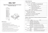
Unit:mm
11.
44
155
10
The length of the master code, from 4 to 6 digits, can be programmed.
Allows up to 1000+10 PINs.
The controller will be locked for 60 seconds upon 5 consecutive invalid PINs.
Controller with keypad sound to avoid incorrect key-in.
Additional input for anti-tailgating function to ensure high security access control.
Built-in light sensor detection switch for vandal resistance.
Non-volatile memory control can retain all PIN codes in event of power failure.
Dual relay outputs for electric lock devices and other access control systems.
Aluminum alloy casing with vandal resistant screws for enhanced safety and durability.
Epoxy sealed for waterproof function (IP65).
Designed with piezo keypad technology.
2 relays (N.O./COM./N.C.)

Note:
1. It is suggested to use a linear power supply unit to prevent power rating reduction
from the keypad.
2. It is suggested to use #22~26 AWG insulation wire.
3.
The exit button contacts are in a N.O. position.
4. With CE qualified EMC specification.
5. The door strike or relay must have a varistor or a diode across the door strike
terminals to suppress the back EMF of the strike – failure to do so will damage the
relay contacts and electronic components, or even burn the controller.
1. Master Code
The master code comprises a four-digit code and is used to access programming
functions of the digital keypad and cannot be used for access request i.e. it cannot
be the same as other PINs. The default master code is 1234. Under normal operation,
entering PINs will gain access. In the programming mode, the keypad can be used to
add/delete PINs, set relay strike time and other operation functions.
2. Entering Programming Mode
Enter the master code twice 1234 1234 to enter programming mode (1 beep, and
Yellow LED is on).
3. Setting Relay Strike Time
The relay strike time determines the amount of time that the door remains unlocked
after a valid PIN is entered.
NOTE: For both Relay 1 & Relay 2, entering 00 sets relay strike time to 0 second,
entering 05 indicates setting up 5 seconds, and so on.
a.Enter programming mode.
b.Press 1 for Relay 1 (Yellow LED flashes).
Press 5 for Relay 2 (Yellow LED flashes).
c.Press 00~99 (1 beep, and Yellow LED is on).
d.Press # (1 beep) to be back to standby mode (Blue LED is on).
4. Clearing Memory of All PINs
a.Enter programming mode.
b.Press 8 (Yellow LED flashes).
c.Press 88 (Yellow LED is on, and 7 beeps).
d.Press # (1 beep) to be back to standby mode (Blue LED is on).
5. Resetting Controller Parameters to Factory Default Value
a.Enter programming mode.
b.Enter
8 (Yellow LED flashes).
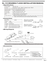
Wiring Diagrams
Operation Instructions
+
12VDC
+
+
+
N.C.1
COM.1
N.O.1
PB1
PB2
REED
N.C.2
COM.2
N.O.2
GND
+
+
REED
12~24VDC
Diode
Power Supply Unit
Varistor
Electric Lock 1
Fail-safe Mode
(Varistor is Required)
EXIT Button1
EXIT Button 2
Door Closed=N.O.
Door Open=N.C.
Electric Lock 2
Fail-secure Mode
Power Supply Unit
(Diode is Required)
Factory Default Setting:
Master Code
1234
4 (digits)
Relay Strike Time 1 second
Pressed Key Time Delay
5 seconds
(fixed)
Programming Mode Time Delay
30 seconds
(fixed)
6. When the digital keypad controller is first supplied with power, please wait until
Green LED flashes(8 beeps and Blue LED is on) to enter standby mode.
DG-185
Digital Keypad
GEM-800
Electric Lock
EB220N
Electric Dropbolt
GK-300
Electric Strike
(Timed)
or or
N.C. (Fail-safe)/N.O.(Fail-secure) Switchable
N.C.1
COM.1
N.O.1
PB1
Red
Black
Light
Green
Pink
White
Orange
Yellow
Brown
Gray
Purple
Blue
Green
PB2
REED
N.C.2
COM.2
N.O.2
GND
PB
GND
12VDC
1A
12VDC
1.5A
N.C.
N.O.
COM.
N.O.
N.O.
COM.
PBT-800
AS-500
ANSI Size
European Standard Size
Exit Button

Warranty:
The product is warranted against defects in material and workmanship while used in
normal service for a period of 1 year from the date of sale to the original customer.
The GEM policy is one of continual development and improvement; therefore GEM
reserves the right to change specifications without notice.
c.Enter 99 (1 beep, and Green LED flashes) to be back to standby mode (Blue
LED is on).
6. Adding PINs to Relay 1
A. a. Enter programming mode.
b. Enter a slot position 000-999(Green LED will be on to indicate the slot position is
available).
d. Press # (1 beep) to be back to standby mode (Blue LED is on).
NOTE:
Master Code must NOT be the same as PIN codes.
B.
a. Enter programming mode.
b. Enter a slot position 000-999 (Red LED will be on to indicate the slot position is
unavailable).
c. Press (1 beep) to delete data from the slot position(Green LED is on).
d. Press # (Yellow LED is on) to be back to programming mode.
e. Repeat Step 6–A to add a new PIN.
7. Adding PINs to Relay 2
A. a. Enter programming mode.
b. Press 4 (Yellow LED flashes).
c. Enter a slot position 00-09(Green LED will be on to indicate the slot position is
available).
d. Press 4-digit PIN (1 beep, and Yellow LED is on).
B.
a. Enter programming mode.
b. Press 4 (Yellow LED flashes).
c. Enter a slot position 00-09(Red LED will be on to indicate the slot position is
unavailable).
d. Press (1 beep) to delete data from the slot position (1 beep, and Green
LED is on).
e. Press # to be back to programming mode (Yellow LED is on).
8. Changing Master Code
a.Enter programming mode.
b.Press
3 (Yellow LED flashes).
c.Enter 4-digit master code twice i.e. 4567 4567 (1 beep, and Yellow LED is on).
d.Press # (1 beep) to be back to standby mode (Blue LED is on).
9. Turning Anti-Tamper Alarm Function ON/OFF (Default setting is ON)
a.Enter programming mode.
b.Press
6 (Yellow LED flashes).
c.Press 01 (1 beep, and Yellow LED is on) – function OFF.
Press 02 (1 beep, and Yellow LED is on) – function ON.
d.Press # (1 beep) to be back to standby mode (Blue LED is on).
12. Resetting Master Code to Default Value
a. Turn off power and energize again (Green LED flashes).
Copyright ©
All Rights Reserved.
P-MU-DG-185 Published: 2015.06.11
Appendix
1
2
3
4
5
6
7
8
9
10
User User Name Slot Number PIN#
d. Set up the length of Master Code: Press 4 to set up the length as 4 digits, press 5
as 5 digits, or press 6 as 6 digits(7 beeps and Yellow LED is on).
c. Press 0 4.
11. Changing the Length of Master Code
a. Enter programming mode.
b. Press 9 (Yellow LED flashes).
e. Press # (1 beep) to be back to standby mode (Blue LED is on).
b. Press ##### to be back to standby mode (Blue LED is on). Then the master code
is reset to default value.
(If the default value is 4 digits, the master code is 1234; if 5 digits, 12345; if 6
digits, 123456).
10. Turning Lock-out Function ON/OFF (Default setting is ON)
a.Enter programming mode.
b.Press 7 (Yellow LED flashes).
c.Press 01 (1 beep, and Yellow LED is on) – function OFF.
Press 02 (1 beep, and Yellow LED is on) – function ON.
d.Press # (1 beep) to be back to standby mode (Blue LED is on).
c. Press 4-digit PIN (1 beep, and Yellow LED is on).
e. Press # (1 beep) to be back to standby mode (Blue LED is on).
f. Repeat Step 7-A to add a new PIN.
/