Page is loading ...

AUBER INSTRUMENTS WWW.AUBERINS.COM
2019.01 P1/6
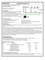
SWA-2451A PID TEMPERATURE CONTROLLER INSTRUCTION MANUAL
Version 1.0 (Jan, 2019)
1. Caution
• This controller is intended to control equipment under normal operating
conditions. If failure or malfunction of the controller may lead to abnormal
operating conditions that may result in personal injury or damage to the
equipment or other property, devices (limit or safety controls) or systems
(alarm or supervisory) intended to warn of or protect against failure or
malfunction of the controller must be incorporated into and maintained as
part of the control system.
• Installing the rubber gasket supplied will protect the controller front panel
from dust and water splash (IP54 rating). Additional protection is needed for
higher IP rating.
• This controller carries a 90-day limited warranty. This warranty is limited to
the controller only.
2. Specifications
Table 1. Specifications
Input Type
Thermocouple: K, E, J, T, S. RTD: Pt100, Cu50
Input Range
K (-20~2370ºF), S (-20~2912ºF), T (-190~750ºF),
E (-20~1290ºF), J (-20~1651ºF), Pt100 (-200~1100ºF)
Cu50 (-56~302)
Display
Two lines, four digits. Temperature & time or
temperature & set temperature.
Display
Resolution
Temperature: 1° C/° F and 0.1° C/ ° F
Time: 1 second/ minute.
Accuracy
Temperature: ± 0.5% of full input range.
Time: 1 second.
Control Mode
Temperature: PID, manual control, on-off,
Time: timed PID, timed on-off, independent timer
Timer Mode
Single delay, double delay, count up, count down
Timer Range
1 - 9999 seconds or minutes
Anti-Short Cycle
Delay Timer
Range
1 - 200 minutes
Control Output
SSR control output: 12 VDC, 50 mA
Alarm
Timer alarm, process high/low alarm, deviation
high/low alarm
Alarm Output
Relay: 3 A at 240 VAC, 5 A at 120 VAC, or 3 A at 30
VDC
Power Supply
90 ~ 265 VAC, 50 ~ 6 0Hz
Dimension
1.89 x 1.89 x 4.25", or 48 x 48 x 108 mm (1/16 DIN)
Insertion Depth
From front panel: 3.95" or 100 mm
Panel Cutout
1.75 x 1.75" or 44.5 x 44.5 mm
3. Terminal Assignment
TC
1
2
13 14 6
7
8
9
105
SSR out
11 12
+
_
input
85-260VAC
3
4
W
R
+
-
R
RTD
COM
(AL1/ AL2)
To 8
AL1
AL2
RST
To 8
Figure 1. Wiring diagram
Note: Use a wire or a N.C. switch to jump pin 11 and 12 together to enable the
timer.
3.1 Sensor Connection
Please refer to table 3 for the input sensor type (Sn) setting codes. The initial
setting for input is for a type K thermocouple. Set Sn to the correct sensor code if
another type of sensor is used.
3.1.1 Thermocouple
The thermocouple should be connected to terminals 4 and 5. Make sure that the
polarity is correct. There are two commonly used color codes for the K type
thermocouple. US color code uses yellow (positive) and red (negative). Imported
DIN color code uses red (positive) and green/blue (negative). The temperature
reading will decrease as temperature increases if the connection is reversed.
When using ungrounded thermocouple that is in touch with a large conductive
subject, the electromagnetic field picked up by the sensor tip might be too large
for the controller to handle, the temperature display will change erratically. In that
case, connecting the shield of thermocouple to terminal 5 (circuit ground of the
controller) might solve the problem. Another option is to connect the conductive
subject to terminal 5.
3.1.2 RTD sensor
For a three-wire RTD with standard DIN color code, the two red wires should be
connected to the terminals 4 and 5. The white wire should be connected to
terminal 3. For a two-wire RTD, the wires should be connected to terminals 3 and
4. Jump a wire between terminals 4 and 5. Set controller input type Sn to Pt.
3.2 Power to the Controller
The power cables should be connected to terminals 6 and 7. Polarity does not
matter. It can be powered by 120V or 240VAC power source. Neither a
transformer nor jumper is needed to wire it up. For the sake of consistency with
the wiring example described later, we suggest you connect the neutral wire to
terminal 6 and hot to 7.
3.2.1 Timer reset terminals
Terminals 11 and 12 are for connecting a reset switch. If you need to start the
timer after controller is powered up, you should short these two terminals
together with a jumper wire. To use the reset function, these terminals should be
connected to a switch. Open the contact of the switch will rest the timer. Close
the contact of the switch will start the timer. Some applications may need a N.O.
Instruction Manual

AUBER INSTRUMENTS WWW.AUBERINS.COM
2019.01 P2/6
contact and other may need N.C. contact switch. Please see Fig. 7 and 9 for
examples.
3.3 Control output connection
The SSR control output of the controller SWA-2451A provides a pulsed 12V DC
signal for the SSR. Connect terminal 10 to the positive input and terminal 9 to
the negative input of the SSR. See Figure 7 for details.
3.4 For first time users without prior experience with PID controllers, the
following notes may prevent you from making common mistakes.
3.4.1 SSR output power does not come from the input of the SSR. The output
of the SSR is a single pole switch between terminals 1 and 2 of the SSR. The
input of the SSR is for controlling, or triggering the SSR. (Please note we are
talking about the SSR itself, not the SSR control output of the controller).
When switching a North American 240V AC power (2 hot wires), the heater will
be live even when the SSR is off. Users should install a double pole mechanical
switch to the power input, to cut both hot wires at same time when not in use.
3.4.2. For all controller models listed in this manual, the power is controlled by
regulating the duration of on time for a fixed period of time. It is not controlled by
regulating amplitude of the voltage or current. This is often referred as time
proportional control. For example, if the cycle rate is set for 100 seconds, a
60% output means controller will switch on the power for 60 seconds and off for
40 seconds (60/100 = 60%). Almost all high power control systems use time
proportional control because amplitude proportional control is too expensive
and inefficient.
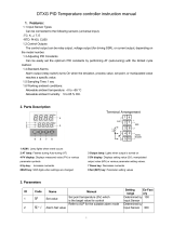
4. Front Panel and Operation
Figure 2. Front panel.
1. PV display: Indicates the sensor read out, or process value (PV).
2. SV display: Indicates the time when timer is used. If timer is deactivated, it
indicates the set temperature (SV). In manual control mode, an “H” is
displayed on the most left digit to indicate number is for percentage of
output (%).
3. Output indicator: It is synchronized with SSR output on the controller
(terminal 9 and 10). When it is on, SSR output is triggered, and your
external SSR & heater (or cooler) are powered.
4. AL1 indicator: It is synchronized with alarm 1 relay (AL1). When timer is on,
it works as the timer relay output indicator. When timer is deactivated, it
lights when Alarm 1 condition meets.
5. AL2 indicator: It is synchronized with alarm 2 relay (AL2). It lights when
Alarm 2 condition meets.
6. Auto-tune indicator: It lights up when auto-tune starts.
7. SET key: Press and hold this key for 3 seconds will enter the temperature
control parameter setting mode. When the controller is in temperature, or
timer parameter setting mode, press this key momentarily will lead the
display to the next parameter.
8. Automatic/Manual function key/Data shift key ◄: press ◄ for 3 seconds to
enter manual tuning mode. Press ◄ for 3 seconds again to exit.
9. Decrement key ▼: Decreases numeric value of the setting value. Press for
3 seconds to enter the timer setting mode.
10. Increment key ▲: Increases numeric value of the setting value. Press for 3
seconds to enter the temperature setting mode.
4.1 Display Modes
8888
20
PV
SV
◄ for 3s
Power on
Figure 3. Display modes
▲For
3s
▼For
3s
PV
SV
SV
PV
SP
100
tE1
20
◄ for 3s
PV
SV
8888
H 0
PV
SV
AL1
999.9
SET for 3s
Mode 1
Mode 2
Mode 3
Mode 4
Mode 5
Display mode 1: Normal operation display.
PV is the abbreviation for Process Value. SV is the abbreviation for Set Value.
When the power is turned on, the upper display window shows the measured
temperature value. If the timer is used, the lower window shows set timer value.
When timer starts, it shows the time as it counts up or down. If the timer is
disabled (INT = 0), the lower display shows the set temperature.
Display mode 2: Changing temperature set value (SV)
Press the ▲key for 3 seconds, and then release it. The decimal point on the
lower right corner will start to flash. Press the ▼or ▲ key to change SV until
the desired value is displayed. If the change of SV is large, press the ◄ key to
move the flashing decimal point to the desired digit that needs to be changed.
Then press the ▼or ▲key to start changing SV from that digit. The decimal
point will stop flashing after no key is pressed for 3 seconds. The changed SV
will be automatically registered without pressing the SET key.
Display mode 3: Timer parameter set up.
Press the ▼ key for 3 seconds to change the display status into timer
parameter setting mode. The upper display window shows the timer parameter
symbol to be changed, the lower display shows its value. Press the ◄, ▼or ▲
to change the setting. Then, press SET to go to next parameter. If no key is
pressed for 10 seconds, the display will return to mode 1 automatically. The
change of value will take effect without the need for pressing the SET key. See
4.14 to 4.16 for more details.
Display mode 4: Manual mode.
Press the ◄ key for 3 seconds to enter the manual mode. In this mode, the
lower display has an H on the most left. The number on the right is the
percentage of power output. Press the ▼or ▲ to adjust the power. Press the
◄ key for 3 seconds again to exit this mode. For more details, please see 4.3.
Display mode 5: Temperature control parameter setting.
Press the SET key for 3 seconds to enter the temperature control parameter
setting mode. The upper display window shows the parameter symbol to be
changed, the lower display shows its value. Press ◄, ▼or ▲ to change the
setting. Then, press SET to go to next parameter. If no key is pressed for 10
seconds, the display will return to mode 1 automatically. The change of value

AUBER INSTRUMENTS WWW.AUBERINS.COM
2019.01 P3/6
will take effect without the need for pressing the SET key. Figure 5 shows the
flow chart of the parameters.
Note: If the controller is locked (see 4.13), only limited parameters (or no
parameters) can be changed.
4.2 Parameter Name, Range and Initial Setting
4.2.1 Alarm parameters
This controller has two alarm outputs: Alarm 1 (AL1, NO relay) and Alarm 2
(AL2, NO relay). Two red alarm indicators are located on the front panel: AL1
and AL2. Alarm 1 and AL1 indicator are synchronized. Alarm 2 and AL2
indicator are synchronized. When the AL1 (AL2) indicator is ON, alarm 1 (alarm
2) relay pulls in. When the AL1 (AL2) indicator is OFF, alarm 1 (alarm 2) relay
drops off.
Each alarm is set by three parameters: ALP, AL and Hy. ALP1, AL1 and Hy1
are for Alarm 1. ALP2, AL2 and Hy2 are for Alarm 2. Alarm 1 can be set as
either temperature alarm (ALP1 = 1 ~ 4) or timer alarm/output (ALP1 = 0).
Alarm 2 can only be used for temperature alarm (ALP2 = 1 ~ 4). See ALP
definition below.
“ALP” defines the type of alarm.
ALP = 0, timer alarm/output (alarm 1 only)
ALP = 1, high limit temperature alarm.
ALP = 2; low limit temperature alarm.
ALP = 3; deviation high temperature alarm.
ALP = 4, deviation low temperature alarm.
Note: When ALP1 is set to 0 (for timer output), parameter AL1 and Hy1 are not
in use. Only ALP1 can be set to 0. ALP2 = 0 is not functional for SWA-2451A.
“AL” is for the alarm temperature setting. When alarm is set for high/low limit
alarm, its value is the temperature that alarm will turn on. When alarm is set for
high/low deviation alarm, its value indicates that the alarm will turn on when
temperature is deviated AL degree from the set temperature (SV). Note: when
alarm is set to deviation alarm (ALP1 / ALP2 is set to either 3 or 4), AL1 / AL2
can only be set to 100 as maximum.
“Hy” is the hysteresis band of temperature alarm. This parameter also uses for
ON/OFF control mode (see 4.2.2 below). In heating mode, for high limit or
deviation high alarm mode, the alarm will turn off when the temperature is Hy
degree below alarm on setting; for low limit and deviation low alarm mode, the
alarm will turn off when temperature is Hy degree above the alarm on setting.
Example 1: ALP1 = 1 (high limit alarm), AL1 = 250, and Hy1 = 5. In this case,
alarm 1 will turn on when temperature goes above 250 degrees (AL1) and turn
off when temperature drop to 245 degrees (AL1-Hy1).
Example 2: SV = 200, ALP1 = 4 (deviation low alarm), AL1 = 10, and Hy1 = 5.
In this case, alarm 1 will turn on when temperature drop to 190(SV-AL1) and
turn off when temperature goes up to 195 (SV-AL1+Hy1).
4.2.2 Hysteresis Band “Hy”
The Hysteresis Band parameter Hy is also referred as Dead Band, or
Differential. It permits protection of the on/off control from high switching
frequency caused by process input fluctuation. Hysteresis Band parameter is
used for on/off control, as well as auto-tune process. For example: When
controller is set for on/off heating control mode, the output will turn off when
temperature goes above SV+ Hy and on again when it drops to below SV-Hy.
4.2.3 At (Auto-tuning)
The auto-tuning function (also called self-tuning) can automatically optimize the
PID parameters for the system. The auto-tuning function will use the on/off
mode to heat up the system until it passes the set point. Then let it cool down. It
will repeat this about three times. Based on the response time of the system,
the built-in artificial intelligence program will calculate and set the PID
parameters for the controller. If your system has a very slow response, the auto
tuning could take a long time.
AT start
AT calculation
AT end
ON
OFF
ON
OFF
ON/OFF PID
Figure 4. Auto tuning
SV
PV
To activate auto-tuning, enter the parameter setting mode, set At = ON. The
“AT” LED on the left lower corner of the controller will light up. Auto-tune will
finish when the AT LED turns off. The newly calculated PID parameters are set
and used for the system. Please note that auto-tuning is only for PID control
mode. There is no need for auto-tune when using ON/OFF mode (when P = 0).
To stop the auto-tuning, enter the parameter setting mode, set At = OFF. Then,
the previous PID parameters values are resumed.
Hy2
1.0
Figure 5. System setup flow chart.
SET
3S
SET
SET
SET
SET
SET
SET
SET
SET
SET
SET
SET
SET
SET
AL1
999.9
ALP 1
Alarm 1 Definition
ALP 2
Alarm 2 Definition
Cool
Cooling Control
OPPO
Output Power
Lock
Configuration Privilege
Sn
Input Type
OPA
Output Mode
CF
Display Unit
DIH
Input High Limit
DIL
Input Low Limit
SC
0.0
P
15.0
I
240
D
30
AT
OFF
t
10
Hy1
1.0
DP
1
ALP2
0
COOL
OFF
Hy
1.0
AL2
0
SET
SET
SET
OPPO
0
LOCK
0
ALP1
0
85.5
10
AL1
Alarm1 Setting
AL2
Alarm2 Setting
SC
Input Offset
P
Proportional Constant
I
Integral Time
D
Derivative Time
At
Auto Tune
T
Cycle Time
Hy
Hysteresis Band
Hy 1
Alarm 1 Hysteresis Band
Hy 2
Alarm 2 Hysteresis Band
dP
Decimal Point Position
Sn
k
OPA
0
Dil
0
dih
999.9
cf
c
Time
SET
SET
SET
SET
SET
PV

AUBER INSTRUMENTS WWW.AUBERINS.COM
2019.01 P4/6
Table 2. System parameters.
Mode 2: Press ▲ key for 3 seconds then release
Code
Sign
Description
Setting Range
Initial
Setting
Remark
Sp
SP
Set Value
Decided by DIL, DIH
100
Mode 5: Press SET key for 3 seconds then release
AL1
AL1
Alarm 1 setting
-1999 ~ +9999 ˚C or ˚F
999.9
4.2.1
AL2
AL2
Alarm 2 setting
-1999 ~ +9999 ˚C or ˚F
0.0
SC
SC
Input offset
-20 ~ 20
0.0
4.10
P
P
Proportional Constant
0.1 ~ 200.0
15.0
4.3.1
I
I
Integral time
0 ~ 2000
240
d
D
Derivative time / delay
time
0 ~ 200
30
At
At
Auto-tune
On/off
Off
4.2.3
t
t
Cycle time
2 ~ 120
2 or 120
4.4
Hy
Hy
Hysteresis band
0.1 ~100.0
1.0
4.2.2
Hy1
Hy1
Alarm 1 hysteresis
band
0.1 ~100.0
1.0
4.2.1
Hy2
Hy2
Alarm 2 hysteresis
band
0.1 ~100.0
1.0
dP
dP
Decimal point position
0 or 1
1
4.6
ALP1
ALP1
Alarm 1 definition
0 ~ 4
0
4.2.1
ALP2
ALP2
Alarm 2 definition
0 ~ 4
1
CooL
COOL
Cooling control
On/Off
Off
4.10
oppo
OPPO
Output power
0
0
4.12
Lock
Lock
Configuration privilege
0 ~ 50
0
4.13
Sn
Sn
Input type
See Table 3
K
4.5
OPA
OPA
Output Mode
0
0
4.9
dIL
DIL
Input low limit
-1999 ~ DIH
0.0
4.7
dIH
DIH
Input high limit
dIL ~ 9999
999.9
CF
CF
Display unit
C, F
C
4.11
Mode 3: Press ▼ key for 3 seconds and release
tE1
TE1
Timer 1
0 ~ 9999
10
4.14
Te2
TE2
Timer 2
0 ~ 9999
0
UPT
UPT
Timer unit and timer
mode
0 ~ 3
0
4.15
INT
INT
Timer control mode
0 ~ 8
1
4.16
4.3 Control action explanations
4.3.1 PID
The values of the P, I, and D parameters are critical for good response time,
accuracy and stability of the system. Using the Auto-Tune function to
automatically determine these parameters is recommended for the first time
user. If the auto tuning result is not satisfactory, you can manually fine-tune the
PID constants for improved performance.
Proportional Constant (P): P is also called the proportional band. Its unit is
the degree of temperature. For example, P = 50 means the proportional band
is 50 degrees. Assuming the set temperature SV = 200. When integral, I, and
derivative, d, actions are removed - the controller output power will change
from 100% to 0% when temperature increases from 150 to 200 ° C. The
smaller the P value is, the stronger action will be for the same temperature
difference between SV and PV. Please note: for on/off control mode, P is
set to 0.
Integral time (I): Brings the system up to the set value by adding to the output
that is proportional to how far the process value (PV) is from the set value (SV)
and how long it has been there. When I decreases, the response speed is
faster but the system is less stable. When I increases, the response speed is
slower, but the system is more stable. When I = 0, the integration is turned off.
It becomes to a PD controller that is useful for very slow system.
Derivative time (d): Responds to the rate of PV change, so that the controller
can compensate in advance before |SV-PV| gets too big. A larger number
increases its action. Setting d-value too small or too large would decrease
system stability, causing oscillation or even non-convergence. Normally, d is
set to ¼ of the I value. However, when the controller is in on/off mode (P = 0)
and cooling control is turned on, d means Delay Timer of the Anti-Short Cycle
Delay (Asd) function. The delay time ranges from 1-200 minutes. (See 4.3.3
for details).
4.3.2 On/off control mode
It is necessary for inductive loads such as motors, compressors, or solenoid
valves that do not like to take pulsed power. It works like a mechanical
thermostat. When the temperature passes the SV+Hy, the heater will turn off.
When the temperature drops back to SV-Hy, the heater will turn on again. (In
cooling mode, the cooler turns on when temperature passes SV+Hy, and turns
off when temperature drops back to SV-Hy). To use the on/off mode, set P =
0 and Hy to the desired band. Then I and D parameters are not used when
controller is in heating mode. It can be left at any value. In the cooling mode,
the D value is used for Anti-Short Delay time. Its value is in minutes (See 4.3.3
for details).
4.3.3 Cooling control
When controller is used for cooling control and load is a compressor, it should
not turn on the compressor when its refrigerant is at high pressure (just after
turned off). Otherwise, the compressor can be damaged in short time. Two
methods are commonly used to prevent the rapid cycling of the compressor.
One is to use on/off control mode (instead of the PID control mode) with wide
enough hysteresis band, and long cycle rate. The other is to use the Anti-Short
Cycle Delay (ASd) function. ASd establishes the minimum time that the N.O.
contacts remain open (after reaching cutout) before closing again. The delay
overrides any Load Demand and does not allow the N.O. contacts to close until
the set time-delay value has elapsed. ASd gives time to release the refrigerant
pressure through evaporator. This controller allows the user to use both
methods to protect the compressor. You should set the P = 0 for on/off mode.
Hy should not be less than 2 degrees unless you really need a tight control. The
cycle rate should be set for 20 second or longer. The D is typically set to 4- 6
(minutes).
4.3.4 Manual mode
Manual mode allows the user to control the output as a percentage of the total
heater power. It is like a dial on a stove. The output is independent of the
temperature sensor reading. One application example is controlling the strength
of boiling during beer brewing. You can use the manual mode to control the
boiling so that it will not boil over to make a mess. The manual mode can be
switched from PID mode but not from on/off mode. This controller offers a
“bumpless” switch from the PID to manual mode. If the controller outputs 75%
of power at PID mode, the controller will stay at 75% when it is switched to the
manual mode, until it is adjusted manually. See Figure 3 for how to switch the
display mode. To activate the manual control, pressing the ◄ key for 3
seconds or until the bottom display shows H at the most left digit. The H
indicating the controller is in manual mode. The number at the right is the
percentage of output. Press the ▼or ▲key to adjust the power. To switch back
to PID mode, pressing the ◄ key for 3 seconds or until the H disappeared.
4.4 Cycle time “t”
It is the time period (in seconds) that the controller uses to calculate its output.
e.g. When t = 2, if the controller decides output should be 10%, the heater will
be on 0.2 second and off 1.8 seconds for every 2 seconds. Smaller t values
result in more precision control. For SSR output, t is recommended for 2 (2
seconds).
4.5 Input sensor type for “Sn”

AUBER INSTRUMENTS WWW.AUBERINS.COM
2019.01 P5/6
Table 3. Code for Sn and its range.
Sn Code
Input Device
Display Range (˚C)
Display Range (˚F)
Cu50
Cu50 (RTD)
-49 ~160
-56 ~ 302
Pt
Pt100 (RTD)
-199 ~610
-198 ~1111
K
K (thermocouple)
-30 ~ 1300
-20 ~ 2370
E
E (thermocouple)
-29 ~ 719
-20 ~ 1292
J
J (thermocouple)
-29 ~ 905
-20 ~ 1651
T
T (thermocouple)
-198 ~ 400
-190 ~ 750
S
S (thermocouple)
-29 ~ 1619
-20 ~ 2912
0 - 5
0 ~5V (0 ~10mA)
Not available for this model.
1 - 5
1 ~5V (4 ~20mA)
4.6 Decimal point setting “dP”
In case of thermocouple or RTD input, dP is used to define temperature display
resolution.
When dP = 0, temperature display resolution is 1º (C or F).
When dP = 1, temperature display resolution is 0.1º (C or F). The temperature
will be displayed at the resolution of 0.1º for input below 1000º and 1º for input
over 1000º (C or F).
4.7 Limiting the control range, “DIL” and “DIH”
1) For temperature sensor input, the “DIL” and “DIH” define the set value range.
DIL is the low limit, and DIH is the high limit. Sometimes, you may want to limit
the temperature setting range so that the operator cannot set a very high
temperature by accident. For example, if you set the DIL = 100 and DIH = 130,
operator will only be able to set the temperature between 100 and 130.
2) For linear input devices, “DIL” and “DIH” are used to define the display span.
For example, if the input is 0 - 5V. DIL is the value to be displayed at 0V and
DIH is the value at 5V.
4.8 Input offset “SC”
SC is used to set an input offset to compensate the error produced by the
sensor or input signal itself. For example, if the controller displays 5ºC when
probe is in ice/water mixture, setting Pb = -5, will make the controller display
0ºC.
4.9 Output definition OPA
This parameter should be kept at zero for this model.
4.10 Heating, and Cooling Mode Selection “COOL”
When COOL = ON, the controller is set for cooling control.
When COOL = OFF, the controller is set for heating control.
4.11 Temperature Unit Selection, Celsius or Fahrenheit, “C, F”
This parameter sets temperature units, C for Celsius, F for Fahrenheit. When it
is for current or voltage input, this parameter is voided.
4.12 OPPO
Output power after controller is turned on. For this controller, it should always
be set to 0.
4.13 Lock up the settings, parameter “LOCK”
To prevent the operator from changing the settings by accident, you can lock
the parameter settings after initial setup. Table 4 shows the privileges
associated with each lock code.
Table 4. LOCK parameter.
LOCK value
SV Adjustment
Other Parameters
0
Yes
Yes
1
Yes
Locked
2 and up to 50
No
Locked
Note: to limit the control temperature range instead of completely locking it,
please refer to section 4.7.
4.14 Set Time for Timer “TE1” and “TE2”
“TE1” is for setting value for the timer. Press ▼ for 3 seconds and change the
value directly.
“TE2” is for setting time of timer 2, it is only valid for dual timer working mode.
4.15 Time Unit and Timer Counting Mode “UPT”
UPT = 0, timer counting down in seconds.
UPT = 1, timer counting down in minutes.
UPT = 2, timer counting up in seconds.
UPT = 3, timer counting up in minutes.
4.16 Timer control mode “INT” *
INT = 0. The timer is disabled. The controller functions as a regular dual
display controller. The lower display shows the set temperature instead of time.
INT = 1. The timer starts after the temperature reaches set point. When set time
reaches, controller’s output stops and timer relay pulls in (turns on). It can be
connected to a buzzer to warn the operator.
INT = 2. The timer starts after the temperature reaches set point. When set time
reached, relay pulls in. The controller’s output will continue to be on.
INT = 3. The timer starts after the temperature reaches set point. When set time
reaches, controller’s output stops. Relay pulls in when timer starts and drops
out when it reaches the set time.
INT = 4. Timer function is independent of temperature controller. After powered
up (or reset), timer starts. The relay will pull in (close) when it reaches the set
time.
INT = 5. Timer function is independent of temperature controller. After powered
up (or reset), timer starts and the relay pulls in (close). It will drop out (open)
when it reaches the set time.
INT = 6. Timer function is independent of temperature controller. After powered
up (or reset), the relay drops out (open) for preset time TE1, then pulls in for
preset time TE2. This process cycles (dual timer cycling mode).
INT = 7. Timer function is independent of temperature controller. After powered
up (or reset), the relay drops out (open) for preset time TE1, then pulls in for
preset time TE2. The relay will remain drop out (open) until reset. After reset,
the relay will keep open for preset time TE1 then pulls in for preset time TE2
again (dual timer no cycling mode).
INT = 8. Timer function is independent of temperature controller. After powered
up (or reset), the relay pulls in for preset time TE1 then drops out (open) for
preset time TE2. This process cycles (dual timer cycling mode).
Note *:
i). When INT value is greater than 0, timer is enabled. The bottom of the display
is for time. In order to let the timer controls the Alarm 1 (AL1), ALP1 should be
set to 0.
ii). Terminal 11 and 12 must be jumped together to enable the timer. Timer can
be started either at powering up of the controller if terminal 11 and 12 are
shorted together, or at shorting terminal 11 and 12 if they are not shorted
together.
iii) While the timer is running, it can be reset by pressing a reset switch (a
normally closed momentary switch) that is connected between terminal 11 and
12.
iv) When INT is set to 1, 2 or 3, after reset, timer starts counting again if
temperature reaches SV. If the temperature is lower than SV in heating mode
(or higher than SV in cooling mode), timer won’t restart until temperature
reaches SV again.
5. Application Examples

AUBER INSTRUMENTS WWW.AUBERINS.COM
2019.01 P6/6
A. 240V heater with alarm buzzer (Oven/Smoker/Cooker)
120VAC
L
TC
+
-
1 13 14
6
2
3
4
5
7
8
9
10
N
120V Buzzer
11 12
SSR
240VAC
SWA-
2451A
L1
L2
3
4
1
2
Heater
Figure 6a. 240V heating element with 120V Buzzer
TC
+
-
1 13 14
6
2
3
4
5
7
8
9
10
240V Buzzer
11 12
SSR
240VAC
SWA-
2451A
L1
L2
3
4
1
2
Heater
Figure 6b. 240V heating element with 240V Buzzer
The heater is driven by a SSR. Sometimes user may want to use the oven for a
preset time and use it multiple times. In this case a normally closed switch
should be used. When controller is on, the cooker will be heated up to 135° F.
The temperature will be hold for 20 minutes. Then the controller will turn off the
heater and turn on the buzzer automatically. User can press the NC switch to
reset the timer. When temperature is over 150°F, buzzer will be turned on
automatically. The parameters that need to be changed from the initial
value: SV = 135° F, ALP1 = 0, ALP2 = 1, AL2 = 150° F, UPT = 1, TE1 = 20,
INT = 1.
B. Espresso machine
Brew Pump
L
1 13 14
6
2
3
4
5
7
8
9
10
N
120V AC
SWA-
2451A
11 12
N. O. Switch
Heater
Fuse
RTD
R
R
W
SSR
M
3
4
1
2
Figure. 7 Typical wiring for espresso machine with PID temperature control and
timer for brew control.
The heater is switched by a SSR. RTD sensor is used. For the brew control, a
rocker switch, or a normally open switch on the espresso machine for brew
should be used. When the switch turns on, the pump will run 25 second and
stop automatically. User need to turn off and turn on the switch again to make
another shot. The parameters need to be changed are: Sn = Pt, SV = 220,
ALP1 = 0, UPT = 2, TE1 = 25, INT = 5.
6. Trouble Shooting
6.1 Timer won’t start
Check the connection between terminal 11 and 12. These two terminals must
be jumped together to enable the timer. A momentary NC switch on pin 11 and
12 can serve as a timer-reset switch.
6.2 No heating
The OUT LED is synchronized with output relay. If there is no heat when it is
supposed to, check the OUT first. If it is not lit, the controller parameter setting
is wrong. If it is on, check external SSR (if the SSR’s red LED is ON). If the SSR
is ON, then the problem is either the SSR, its wiring, or the heater. If the
external switching device is not on, then the problem is either the controller
output, or the external switch device.
6.3 Poor accuracy
Please make sure calibration is done by immersing the probe in liquid.
Comparing with reference in air is not recommended because response time of
sensor depends on its mass. Some of our sensor has response time >10
minutes in the air. When the error is larger than 5 ° F, the most common
problem is improper connection between the thermocouple and the controller.
The thermocouple needs to be connected directly to the controller unless
thermocouple connector and extension wire is used. Copper wire or
thermocouple extension wire with wrong polarity connected on the
thermocouple will cause the reading drift more than 5 ° F.
6.4 Under on/off control mode, although hysteresis is set to 0.3, unit is
running 5 degrees above and below.
If the Hy is very small and temperature change very fast, user needs to
consider the delay of the cycle time (the parameter t). For example, if cycle time
is 20 seconds, when the temperature passes the SV + Hy after the very
beginning of 20 seconds, relay will not act until it starts the next cycle 20
seconds later. The temperature could be much higher than the set point. User
may change the cycle time to a smaller value, such as 2 seconds, to get a
precise control.
6.5 Display “HH”
This is an input error message. The possible reasons are: the sensor is not
connected or not connected correctly; the sensor input setting is wrong; or the
sensor is defective. In this case, the instrument terminates its control function
automatically. If this happens when using thermocouple sensor, you can short
terminal 4 and 5 with a copper wire or paper clip. If the display shows ambient
temperature, the thermocouple is defective. If it still displays “HH”, check the
input setting, Sn, to make sure it is set to the right thermocouple type. If the Sn
setting is correct, the controller is defective. For RTD sensors, check the input
setting first because most controllers are shipped with the input set for
thermocouples. Then check the wiring. The two red wires should be connected
to terminals 4 and 5. The white wire should be connected to terminal 3.
6.6 Cannot change set temperature
Please check parameter dIH and dIL. These two parameters limit the set
temperature range. If you set dIH and dIL at the same value (like 100), the set
temperature (SP) can only be set as 100, and user cannot adjust it.
Auber Instruments
5755 North Point Parkway, Suite 99
Alpharetta, GA 30022, USA
www.auberins.com
Copyright 2007-2019, Auber Instruments All Rights Reserved.
No part of this manual shall be copied, reproduced, or transmitted in any way
without the prior, written consent of Auber Instruments. Auber Instruments
retains the exclusive rights to all information included in this document.
/