Page is loading ...

Copyright All Rights Reserved.
P-MU-DG600 Ver.D Publish:2010.01.25 Page: - 1 -/ 6
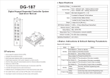
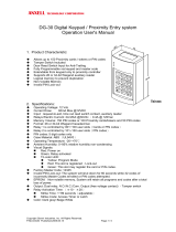
DG-600 Stand Alone Reader
Operation Manual
Ⅰ.Features
1. Memory volume up to 600 proximity cards/tokens and PINs with the programming time up to 0.5
second.
2. Supports Wiegand
26-bit or 44-bit format auxiliary reader.
3. Access modes: a. only proximity card (default setting) b. proximity card+PIN c. proximity card or PIN
4. 5-digit PINs for 3-b and 3-c
5. Logical memory prevents duplicated card setting.
6. Lockout function: The controller will lockout for 60 seconds after entering 5 times invalid PINs or
unsuccessful card attempts. (The keypad without beep during the period time)
7. Controller with keypad sound to avoid incorrect key-in.
8. Built-in tamper switch
9. Non-volatile memory allows remaining all setting codes in the event of total power failure.
10. Removable memory chip in the main control module allows on site replacement in the event of break
down.
Ⅱ. Specifications
Operating Voltage 8.5VDC~16VDC
Current Draw Pull in: 100mA @12VDC, Holding: 50mA @12VDC
RF Frequency 125 KHz
Read Range 10 cm (In noise-free environment)
Keypad
12-digit (0~9,*,#)
Input
1 contact for request-to-exit button
1 contact for door reed switch
1 contact for auxiliary reader
Output
2 relays(Dry contact)2A MAX @30VDC;0.4A @ 120VAC
LED Status Indication 3 LED indicators display (Red/Yellow/Green)
Memory Volume 600 proximity cards/tokens and PINs
Relay Electric Current
2A MAX @30VDC;0.4A @ 120VAC
Relay Strike Time
Relay 1:01~99seconds or Toggle Mode (00)
Ambient Humidity 5%~95% (Non-condensing)
Operating temperature
-20℃~70℃
Format
DG-600E:Wiegand 44 or 26-bit hexadecimal
(EM 64 bits standard R/O or compatible)
DG-600H:Wiegand 26~37 or 26-bit hexadecimal
(125KHz 26~37 bits standard R/O)

Copyright All Rights Reserved.
P-MU-DG600 Ver.D Publish:2010.01.25 Page: - 2 -/ 6
Ⅲ. Indicator Status & Default Setting Parameters
Beep & LED Indication
Mode Signal Status
LED
Standby
Yellow LED slow flash Standby
Green LED stay on Door Relay active
Red LED stay on Alarm Relay active, invalid card, incorrect operation
Programming
Yellow LED stay on Enter programming mode
Yellow LED rapid flash Programming, awaiting input of PINs
Green LED stay on The slot position is available
Red LED stay on The slot position is unavailable
Beep
Standby
1 Beep Valid card, key press, enter programming mode
4 Beeps Invalid card, incorrect PIN
Programming
1 Beep Correct Input data, Exit programming mode
4 Beeps
Incorrect Input data, other incorrect operation,
duplicated card setting
Factory Default Setting
Access Mode Proximity Card Only (00)
Format All Bits
Card Storage(MAX 600 pcs)
None
Master Code 12345 (5 digits)
Alarm Function (All) Function disabled (00)
Relay Strike Time 5 seconds
Pressed Key Time Delay 5 seconds
PIN Code Input Waiting Time 5 seconds
Programming Mode Time Delay 25 seconds
Terminal connections
CN1 Description CN2 Description
12 + 8.5V to 16VDC 12
+ 8.5V to 16VDC(auxiliary reader)
V GND V
Power Ground(auxiliary reader)
D Electric lock D1
Wiegand Data 1(auxiliary reader)
C Electric lock, Alarm(Com.) D0
Wiegand Data 0(auxiliary reader)
A Alarm LED
LED(auxiliary reader)
E Door reed switch BEEP
BEEP(auxiliary reader)
B Request-to-exit

Copyright All Rights Reserved.
P-MU-DG600 Ver.D Publish:2010.01.25 Page: - 3 -/ 6
Ⅳ. Wiring Diagram
Note:
1. The distance between auxiliary reader and DG-600 should not more than 20m or less than 30cm for
signal transmission. It is suggested to use #22~26 AWG insulation wire.
2. When DG-600E connects to an external auxiliary reader of Wiegand 26 bits format, please weld short
JP1 to Wiegand 26 bits (hexadecimal). (Default is Wiegand 44 bits)
3. DG-600H, if short JP1 turns to Wiegand 26 bits, only Wiegand 26 bits output from external auxiliary
reader can be read.
4. After JP1 is changed, please reset and input again.
5. It is suggested to use a linear power supply unit to prevent reading range reduction at the card reader.

Copyright All Rights Reserved.
P-MU-DG600 Ver.D Publish:2010.01.25 Page: - 4 -/ 6
6. The door strike or relay must have a varistor or a diode across the door strike terminals to suppress
the back EMF of the strike – failure to do so will damage the relay contacts and electronic components,
or even burns the controller.
7. Exit button is at N.O. contact.
8. It is suggested to connect to an external relay to activate the alarm. (C.A. contact)
9. Meet CE standard
Ⅴ. Operation Instruction
Enter Programming Mode
Enter the master code twice (Default value:“12345”) to enter Programming mode (2 Beeps, Yellow
LED stay on)
Exit Programming Mode
Press # to exit programming mode or after 25 seconds if no data entered, it will automatically exit the
setting mode and back to standby mode.
Set the Access Mode (In programming mode)
Press*0 +??
??=00, Proximity Card Only (1 beep) (Default)
??=01, Proximity Card or PIN (1 beep)
??=02, Proximity Card + PIN (1 beep)
Note 1:In “Proximity Card + PIN” mode, it has only one chance to read the card and enter the PIN.
Incorrect PIN will back to standby mode and has to repeat the above step again.
Note 2:In “Proximity Card + PIN” mode, the card will be deleted upon 5 consecutive master codes or
invalid PINs attempt.
Add and delete a proximity card (In programming mode)
Select slot position 000~599 (Red LED stay on indicate the slot position is available)
Select slot position 000~599
a. Green LED stay on: The slot position is available
Read new card (1beep, yellow LED flash) Enter 5-digit PINs (LED off)
(Repeat)
Duplicated card setting (4 beeps)
b. Red LED stay on: The slot position is unavailable
1. Press ** to delete the data from the slot position (Green LED stay on)
2. Read new card

Copyright All Rights Reserved.
P-MU-DG600 Ver.D Publish:2010.01.25 Page: - 5 -/ 6
3. Repeat the step a or select another slot position
4. Press # back to standby mode (1 beep, yellow LED off)
Note: 1. In any access mode, read the card and enter the PINs must be at the same time.
2. Master code cannot be used for PINs.
Set the Relay Strike Time (In programming mode)
Press*1 + ??
1. ??=01~99 seconds, press 05 will set the door relay time to 5 seconds. (1 beep)
2. In Toggle mode, ??=00 (1 beep)
In Toggle mode, the relay will switch between N.C. contact and N.O. contact upon enter PIN once.
Set Door Alarm Time (In programming mode)
Press*2 + ?? (??=10~990 seconds, press 05 will set the door relay time to 5 seconds.) (1 beep)
Function Off: Press 00 (1 beep)
Example 1: Door Held Open Alarm
If the relay strike time is set for 5 seconds, and the door alarm time is set for 10 seconds, the
following will happen:
If the door is opened via a valid card or PINs and remains open for more than 15 seconds, an audible
alarm will sound and the red LED will flash until the door has been closed.
This activation is controlled by「E」 and 「V」contact.
Example 2: Vandal Resistant Alarm
If the door is opened without the use of a valid card or PINs, the audible alarm will sound and the red
LED will flash until the door has been closed.
This activation is controlled by「E」 and 「V」contact.
Example 3: Tamper Switch
The main panel has a tamper switch installed, if the main panel is opened, the audible alarm will
sound and the red LED will flash until the panel has been closed.
Change Master Code (In programming mode)
Press*3 + 5-digit master code (1 beep)

Copyright All Rights Reserved.
P-MU-DG600 Ver.D Publish:2010.01.25 Page: - 6 -/ 6
Reset (Insert the reset jumper into ST1 2-3)
Note: Must release the jumper as soon as yellow LED flash, otherwise could clear all PINs
Warranty:
The product is warranted against defects in material and workmanship while used in normal service for a
period of 1 year from the date of sale to the original customer. The GEM policy is one of continual
development and improvement; therefore GEM reserves the right to change specifications without notice.
Master Code reset to default
value “12345” (1 beep, green
LED flash)
Yellow LED flash:
Waiting 10 seconds to
proceed another
command.
Master Code reset to default value and clear all PINs
(1 beep, red LED flash)
Insert the jumper back into 1-2
/