Page is loading ...

POWER TOOLS
TECHNICAL DATA
AND
SERVICE MANUAL
DUST COLLECTION
CIRCULAR SAW
C 7YA
SPECIFICATIONS AND PARTS ARE SUBJECT TO CHANGE FOR IMPROVEMENT
LIST No. 0590 Nov. 2000
C
MODEL
C 7YA

Page
CONTENTS
1. PRODUCT NAME........................................................................................................................... 1
2. MARKETING OBJECTIVE ............................................................................................................. 1
3. APPLICATIONS.............................................................................................................................. 1
4. SELLING POINTS .......................................................................................................................... 1
4-1. Selling Point Descriptions ............................................................................................................... 2
5. SPECIFICATIONS .......................................................................................................................... 4
6. COMPARISONS WITH SIMILAR PRODUCT ................................................................................ 5
7. PRECAUTIONS IN SALES PROMOTION ..................................................................................... 6
7-1. Handling Instructions ...................................................................................................................... 6
7-2. Cautions Plates ............................................................................................................................... 6
7-3. Inherent Drawbacks of Dust Collection Circular Saw Requiring Particular Attention during
Sales Promotion .............................................................................................................................. 6
8. PRECAUTIONS IN DISASSEMBLY AND REASSEMBLY ............................................................ 7
8-1. Disassembly ................................................................................................................................... 7
8-2. Reassembly .................................................................................................................................... 7
9. STANDARD REPAIR TIME (UNIT) SCHEDULES ........................................................................11
Assembly Diagram for C 7YA............................................................................................................... 12

--- 1 ---
1. PRODUCT NAME
Hitachi Dust Collection Circular Saw, Model C 7YA
2. MARKETING OBJECTIVE
Fiber-cement boards that resist moisture damage and termite attack are gaining in popularity as a 2 x 4
construction material in the U.S., New Zealand and Australia. Occupational health and safety regulations are
becoming very strict with regard to any dust deemed "hazardous to health" --- fiber cement products fall within this
category.
The Model C 7YA has been developed as a dust collection and control type circular saw which will contribute to a
cleaner work environment and protect job-site workers from dust hazard.
3. APPLICATIONS
Cutting of fiber cement board
4. SELLING POINTS
Saw blade can be easily
replaced.
Selectable from two dust disposal methods
(dust guide or dust bag)
360˚ adjustable dust guide
Excellent dust collection and
cutting efficiencies
(4T diamond tip blade adopted)
Vertically movable
transparent slide cover

--- 2 ---
Guide groove
Dust
4-1. Selling Point Descriptions
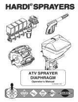
(1) Excellent dust collection and cutting efficiencies
(4T diamond tip blade adopted)
The Model C 7YA is equipped with a gear cover,
a saw cover and a slide cover to collect dust of
fiber cement boards or to control the discharging
direction of dust. Since dust is discharged through
a guide groove composed of the above three covers
(shown in the right figure) toward the outlet at a high
speed, scattering of dust is minimized and the dust
bag can collect dust efficiently.
C 7YA
C
Item
Model
In addition, the Model C 7YA is equipped with a 4T diamond tip blade that is specifically designed for cutting
fiber cement boards (HARDI PLANK, HARDI PANEL, etc.). The 4T diamond tip blade cuts fiber cement
boards well without decreasing the peripheral speed, and particles of dust are relatively larger. Thus, the
Model C 7YA provides excellent dust collection efficiency. C is equipped with a 28T TCT blade and provides
less cutting and dust collection efficiencies than those of the Model C 7YA. The table and figure below show a
comparison between the Model C 7YA and C concerning the dust collection and cutting efficiencies.
Comparison in dust collection rate
4 thicknesses
3 thicknesses
Unmeasurable (*2)
(*1) When the slide cover is fully opened: 80%
(*2) Cutting efficiency for 4 thicknesses of HARDI PLANK is unmeasurable because the saw blade
becomes dull.
(Note) The dust collection rates vary depending on the cutting conditions. Use these factory test results
as a reference, comparison purposes only.
Cutting conditions
Material: HARDI PLANK
(Thickness: 5/16", Width: 12")
Cutting length: 5 m
85% (*1)
81%
47%
0
10
2
4
6
8
12
14
m/min.
45.9
26.2
30.3
39.4
6.6
13.1
19.7
0
ft/min.
2
3
4
(8.8)
(6.6)
(4.4)
kgf
lbs.
Material: HARDI PLANK (Thickness: 5/16", Width: 12")
C 7YA (Thickness: 1)
C 7YA (Thickness: 4)
C (Thickness: 1)
Thrust
Feeding speed
Comparison in cutting efficiency

--- 3 ---
Ledge
(2) Selectable from two dust disposal methods (dust guide or dust bag), 360˚ adjustable dust guide
Dust disposal method is selectable either installing the dust guide or the dust bag. The dust guide is 360˚
adjustable to control the dust discharging direction so that scattering of dust toward the operator can be
avoided. The dust bag can contain 80% or more dust. C has only the dust box for dust disposal.
Dust guide Dust bag
(3) Saw blade can be easily replaced
The Model C 7YA enables easy replacement of saw blade without removing any other part in the same
manner as a circular saw. C requires a bothersome removal of the dust box before replacing the saw blade.
(4) Vertically movable transparent slide cover
Since dust is generated at the cutting edge of a circular saw blade, shielding the cutting edge is the best
method to minimize scattering of dust. However, such shield may block the cutting line on the workpiece from
the operator's view and the workability may be impaired. The Model C 7YA is equipped with a vertically
movable slide cover so that the operator can open and close the slide cover to see the cutting edge.
The slide cover is transparent and the operator can see the cutting edge even if the slide cover is closed
completely. In addition, a ledge is provided at the bottom of the slide cover as shown below to minimize
scattering of dust toward the operator even if the circular saw is operated with the slide cover opened.
C is equipped with a dust box having a peephole to see the cutting edge, however, dust scatters toward the
operator through the peephole.

--- 4 ---
Standard accessories
Dust guide
••••••••••••••••••••••••••••••••••••••••••••••••••••••••••••
1
Dust bag
•••••••••••••••••••••••••••••••••••••••••••••••••••••••••••••
1
Wrench
••••••••••••••••••••••••••••••••••••••••••••••••••••••••••••••••
1
Wing bolt (B)
•••••••••••••••••••••••••••••••••••••••••••••••••••••••••
1
Lock spring
•••••••••••••••••••••••••••••••••••••••••••••••••••••••••••
1
Type of motor
Enclosure
Weight
47 mm (1-27/32")
Polycarbonate resin
Die-cast aluminum alloy
60 mm (2-3/8")
Max. cutting depth
AC single phase
at 90˚
Trigger switch
Power source
Type of switch
Die-cast aluminum alloy
Power input
at 45˚
AC single phase commutator motor
Housing, handle cover
Gear cover, saw cover
Voltage [V]
Current [A]
Full-load output
Rotation speed
Cord
Safety cover
Base
No-load
Gross
Net
Full-load
Type
Overall length
Die-cast aluminum alloy
5,500/min.
700 W
1,400 W *
4,050/min.
4.9 kg (10.8 lbs.)
6.4 kg (14.1 lbs.)
2.5 mm (8.2 ft.)
120
13
230
6.7
240
6.2
* Power input is subject to change according to market area.
5. SPECIFICATIONS
185 mm (7-1/4")
Two core cabtire cable
Model
Saw blade diameter
C 7YA
Arbor
15.88 mm (5/8") (For USA), 20 mm (For AUS, NZL)
LW
H
L = 299 mm (11-25/32")
H = 243 mm (9-9/16")
W = 234 mm (9-7/32")
Optional accessories
Guide (Rip fence)
••••••••••••••••••••••••••••••••••••••••••••••••••
1

--- 5 ---
* Rated voltage
No-load speed
Spindle lock
Standard accessories
47 (1-27/32")
Dust bag, dust guide
Item
Dust control
60 (2-3/8")
Cutting
depth
185 (7-1/4")
90˚
13
Saw blade dia.
* Rated current
No-load noise
45˚
120
Full-load torque
Max. output
Insulating construction
Type of switch
Bearings
C 7YA
Trigger switch
Double
90
Provided
5,500
5.3 (11.7)
Dust guide
Dust bag
Wrench
Bolt
Spring
5,380
Maker, model
mm (in.)
mm (in.)
mm (in.)
V
A
Weight (exclude cord)
No-load speed
Full-load speed
/min.
kg (lbs.)
/min.
/min.
N•m (ft-lbs.)
W
dB
Material of base
4,050
0.170 (0.035)
1,680
Ball bearing and needle bearing
Nickel-plated aluminum diecast
28T TCT blade
Guide (Rip fence)
Wrench
HITACHI
C
30 (1-3/16")
Plastic dust box
60 (2-3/8")
185 (7-1/4")
13
120
5,800
4.9 (10.8)
5,650
4,050
0.170 (0.035)
1,880
90
Trigger switch
Double
Provided
Ball bearing and needle bearing
Aluminum plate
Catalog specifications
Structural constructions
Characteristic
6. COMPARISONS WITH SIMILAR PRODUCT
* Specification for the U.S.A. market
Optional accessories
Guide (Rip fence)
16T TCT blade

--- 6 ---
7. PRECAUTIONS IN SALES PROMOTION
In the interest of promoting the safest and most efficient use of the Model C 7YA Dust Collection Circular Saw by
all of our customers, it is very important that at the time of sale the salesperson carefully ensures that the buyer
seriously recognizes the importance of the contents of the Handling Instructions, and fully understands the
meaning of the precautions listed on the Name Plate attached to each tool.
7-1. Handling Instructions
Although every effort is made in each step of design, manufacture, and inspection to provide protection against
safety hazards, the dangers inherent in the use of any electric tool cannot be completely eliminated. Accordingly,
general precautions and suggestions for the use of electric power tools, and specific precautions and suggestions
for the use of the Circular Saw are listed in the Handling Instructions to enhance the safe, efficient use of the tool
by the customer. Salespersons must be thoroughly familiar with the contents of the Handling Instructions to be
able to offer appropriate guidance to the customer during sales promotion.
7-2. Cautions Plates
The following basic safety precautions are listed on the Name Plate attached to the main body of each tool.
For Australia and New Zealand
7-3. Inherent Drawbacks of Dust Collection Circular Saw Requiring Particular Attention during Sales
Promotion
(1) Protective glasses and dustproof mask
When you use the tool, make certain that you wear the protective glasses and the dustproof mask.
(2) Dust bag, or dust guide
Make it absolutely sure when you use the tool to mount any one of the dust bag or dust guide that is provided
as a standard accessory.
(3) When using dust bag;
Never attempt to saw any material like metal and so on that give off sparks. Such action can lead to fire or
injury.
(4) When using dust guide;
The dust guide can change the direction of the discharge direction. Never point it in the direction of the
worker.
For the U.S.A.

--- 7 ---
Push
49 mm
(1-15/16")
Jig
60 mm
(2-23/64")
8-1. Disassembly
(1) Prior to attempting further disassembly, ensure without fail that the Saw Blade is removed to prevent damage
to its cutting edge, and to avoid possible serious accident.
(2) Remove the Safety Cover [8]:
First, disconnect the Return Spring [9]. Then, loosen the two Seal Lock Flat Hd. Screws M4 x 10 [13], and
take off the Bearing Cover [12]. The Safety Cover [8] can then be removed.
(3) Remove the Bearing Holder [3] together with the Spindle and Gear Set [2]:
After removing the Safety Cover [8] as described above, loosen the two Seal Lock Flat Hd. Screws M5 x 14
[4], and take off the Bearing Holder [3] together with the Spindle and Gear Set [2].
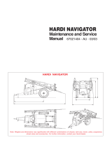
(4) Separate the Spindle and Gear Set [2] from the Bearing Holder [3]:
As illustrated in Fig. 1, support the Bearing Holder [3]
with an appropriate tubular jig, and push down on the end
of the Spindle and Gear Set [2] with a hand press to separate
the Spindle and Gear Set [2] from the Bearing Holder [3].
(5) Remove the Armature Ass'y [31]:
First, remove the Carbon Brushes [42]. Next, take off the
Clamp Lever [68], loosen the Clamp Nut [70], and remove the
Bolt (Square) M6 x 20 [52]. Then, loosen the Machine Screws (W/Washers) M5 x 45 [22], and separate the
Housing Ass'y [23] from the Gear Cover [36]. The Armature Ass'y [31] will remain within the Housing Ass'y
[23]. With a wooden or plastic hammer, tap gently on the outside of the Housing Ass'y [23] to loosen and
remove the Armature Ass'y [31]. At this time, be very careful not to hit the fan on the Armature Ass'y [31].
(6) Remove the Base Ass'y [63]
Extract the Roll Pin D6 x 40 [64] which connects the Base Ass'y [63] and the Housing Ass'y [23], and separate
them.
8. PRECAUTIONS IN DISASSEMBLY AND REASSEMBLY
Disassembly and reassembly procedures which require particular precautions are described below.
The [Bold] numbers in the descriptions below and the circled numbers in the following figures correspond to the
item numbers in the Parts List and the exploded assembly diagram for the Model C 7YA.
Be sure to unplug the Model C 7YA from the wall outlet before performing disassembly or replacement of the saw
blade.
8-2. Reassembly
Reassembly can be accomplished by following the disassembly procedures in reverse. However, particular
attention should be given to the following items.
(1) Tightening torque for fastening screws:
M4 Machine Screws
•••••••••••••••••••••••••••••••••••••••••••••••••••
14 to 24 kg•cm (12 to 21 in-lbs.)
M5 Machine Screws
•••••••••••••••••••••••••••••••••••••••••••••••••••
28 to 50 kg•cm (24 to 43 in-lbs.)
M8 x 15.5 Flange Bolt [16]
••••••••••••••••••••••••••••••••••••••••••
80 to 120 kg•cm (70 to 105 in-lbs.)
D4 Tapping Screws
•••••••••••••••••••••••••••••••••••••••••••••••••••••
15 to 25 kg•cm (13 to 22 in-lbs.)
D5 Tapping Screws
•••••••••••••••••••••••••••••••••••••••••••••••••••••
25 to 35 kg•cm (22 to 30 in-lbs.)
Fig. 1

--- 8 ---
(2) Reassembly of the Armature Ass'y [31]:
Prior to assembling the Armature Ass'y [31], ensure that the Rubber Ring [35] is properly inserted into the
groove of the bearing case within the Gear Cover [36]. At this time, be careful not to damage the Rubber Ring
[35].
(3) Reassembly of the Lock Lever [32] (See Fig. 2.):
A. Position the Lock Lever [32] between the fan and
the Ball Bearing 6201VVCMPS2L [34], and carefully
assemble it together with the Armature Ass'y [31] into
the Gear Cover [36].
B. Carefully ensure that both ends of the flat spring on
the Lock Lever [32] are properly supported inside the
ribs of the Gear Cover [36], as illustrated in Fig. 2.
C. When assembly of the Lock Lever [32] is completed
(when the Gear Cover [36] has been assembled to the
Housing Ass'y [23]) and fastened with the Machine
Screws (W/Washers) M5 x 45 [22], push the Lock Lever [32]
by hand and ensure that it returns smoothly to its original
position when released.
(4) Lubrication:
Liberally apply designated lubricants as follows:
Nippeco SEP-3A (Code No. 930035) within the Gear Cover: 15 gr. (.528 oz)
Multemp PS No. 2 (Code No. 939301 or 939536) in the Ball Bearings.
(5) Wiring diagrams (See Figs. 3 to 4.):
A. For AUS and NZL
Fig. 3
Fig. 2
Connector [45] (For NZL)
Pillar Terminal [44] (For AUS)
Noise Suppressor [56]
Switch [57]
Stator Ass'y
Armature
2
3
[32]
[36]
[36]
Flat spring
Rib

--- 9 ---
B. For the U.S.A.
Fig. 4
Switch [57]
Stator Ass'y
Armature
2
3
Pillar Terminal [44]
(6) Internal wire arrangement (See Figs. 5 to 6.):
A. For AUS and NZL
Noise Suppressor [56]
Switch [57]
Terminal number of switch
Internal wire of cord
Creep the internal wires as illustrated.
Fig. 5
Internal wire of stator ass'y
Fig. 6
Terminal number of switch
Switch [57]
Internal wire of stator ass'y
Internal wire of cord
B. For the U.S.A.

--- 10 ---
(7) Insulation tests:
On completion of disassembly and repair, measure the insulation resistance and conduct dielectric strength test.
Insulation resistance: 7MΩ or more with DC 500V Megohm Tester
Dielectric strength: AC 4,000V/1 minute,
with no abnormalities
•••••••••••••••••••••••••••••
220 V to 240 V
(and 110 V for U.K. products)
AC 2,500V/1 minute,
with no abnormalities
•••••••••••••••••••••••••••••••
100 V to 127 V
(except U.K. products)
(8) Cleaning the cover:
Clean the exterior of the tool with a soft cloth moistened with soapy water, and dry thoroughly.
Chloric solvent, gasoline, and thinner will cause plastic components to dissolve.

--- 11 ---
9. STANDARD REPAIR TIME (UNIT) SCHEDULES
MODEL 10 20 30 40
Fixed
Variable
C 7YA
Work Flow
Switch
Cord
Armature
Ball Bearing
6201VVCMPS2L
Ball Bearing
6000VVCMPS2L
Safety Cover
Return Spring
60 min.
50
Housing Ass'y
Stator Ass'y
Gear Cover
Spindle and
Gear Set
Bearing Holder
Ball Bearing
6003VVCMPS2L
Needle Bearing
Base Ass'y
General Assembly

--- 12 ---
DUST COLLECTION CIRCULAR SAW
Model C 7YA
2000• 9 •10
(
E1
)
LIST NO. 0590
ELECTRIC TOOL PARTS LIST

--- 13 ---
PARTS
C 7YA
: ALTERNATIVE PARTS
ITEM
NO.
CODE NO. DESCRIPTION
NO.
USED
REMARKS
1 982-027 NEEDLE BEARING (HK1010) 1
2 302-436 SPINDLE AND GEAR SET 1
3 302-433 BEARING HOLDER 1
4 992-013 SEAL LOCK FLAT HD. SCREW M5X14 2
5 600-3VV BALL BEARING 6003VVCMPS2L 1
6 319-524 WASHER 1
7 961-807 BUSHING 1
8 319-291 SAFETY COVER 1
9 319-523 RETURN SPRING 1
10 319-292 LEVER 1
11 958-523 MACHINE SCREW (W/SP. WASHER) M4X8 2
12 302-435 BEARING COVER 1
13 990-430 SEAL LOCK FLAT HD. SCREW M4X10 2
* 14 302-444 WASHER (A) 1
* 14 302-443 WASHER (A) 1 FOR USA,CAN
15 302-423 WASHER (B) 1
16 302-427 BOLT (W/FLANGE) M8X15.5 1
17 319-288 SAW COVER 1
18 951-039 MACHINE SCREW (W/SP. WASHER) M4X12 4
19 HITACHI LABEL 1
20 319-289 SLIDE COVER 1
21 319-290 WASHER 1
22 302-434
MACHINE SCREW (W/WASHERS) M5X45 (BLACK) 3
23 302-421 HOUSING ASS'Y 1 INCLUD.39,41
* 24 NAME PLATE 1
25 600-0VV BALL BEARING 6000VVCMPS2L 1
26 302-428 WASHER (A) 1
27 937-623 BRUSH TERMINAL 1
* 28 981-373 TUBE (D) 1 FOR USA,CAN
* 29 340-199C STATOR ASS'Y 110V-115V 1 INCLUD.27,28
* 29 340-199G STATOR ASS'Y 220V-230V 1 INCLUD.27
* 29 340-199F STATOR ASS'Y 240V 1 INCLUD.27
30 302-430 FAN GUIDE 1
* 31 360-187U ARMATURE ASS'Y 110V-115V 1 INCLUD.25,26,33,34
* 31 360-187E ARMATURE 220V-230V 1
* 31 360-187F ARMATURE 240V 1
32 302-431 LOCK LEVER 1
33 302-429 DUST WASHER (B) 1
34 620-1VV BALL BEARING 6201VVCMPS2L 1
35 302-432 RUBBER RING 1
36 319-287 GEAR COVER 1
37 961-729 CUSHION 1
38 949-794 FLAT HD. SCREW M6X20 (10 PCS.) 1
39 938-477 HEX. SOCKET SET SCREW M5X8 2
40 301-653
TAPPING SCREW (W/FLANGE) D4X20 (BLACK) 3
41 983-362 BRUSH HOLDER 2
42 999-038 CARBON BRUSH (1 PAIR) 2
43 961-781 BRUSH CAP 2
* 44 938-307 PILLAR TERMINAL 1 FOR AUS,USA,CAN
* 45 959-140 CONNECTOR 50091 (10 PCS.) 1 FOR NZL
* 46 958-049 CORD ARMOR D8.2 1
*
9
---
00

--- 14 ---
PARTS
C 7YA
ITEM
NO.
CODE NO. DESCRIPTION
NO.
USED
REMARKS
* 46 940-778 CORD ARMOR D10.7 1
47 981-373 TUBE (D) 1 FOR CORD
48 960-266 CORD CLIP 1
49 984-750 TAPPING SCREW (W/FLANGE) D4X16 2
* 50 500-439Z CORD 1 (CORD ARMOR D8.2)
* 50 500-434Z CORD 1 (CORD ARMOR D10.7) FOR USA,CAN
51 960-251 HEX. HD. TAPPING SCREW D5X65 2
52 942-808 BOLT (SQUARE) M6X20 1
53 311-837 SPACER M4 1
54 311-836 TP-SCREW M4X14 1
* 55 981-373 TUBE (D) 1 FOR NZL,AUS
* 56 930-039 NOISE SUPPRESSOR 1 FOR AUS,NZL
57 302-446 SWITCH (1P PILLAR TYPE) W/O LOCK 1
58 302-422 HANDLE COVER 1
59 302-438 WING BOLT (A) M6X20 1
60 949-455 SPRING WASHER M6 (10 PCS.) 1
61 949-425 WASHER M6 (10 PCS.) 1
62 306-082 BEVEL PLATE 1
63 319-293 BASE ASS'Y 1 INCLUD.59-62,67
64 949-686 ROLL PIN D6X40 (10 PCS.) 1
65 302-697 WING BOLT (B) M6X16.5 1
66 947-859 LOCK SPRING 1
67 302-439
SLOTTED HD. SET SCREW (SEAL LOCK) M6X8
1
68 302-440 CLAMP LEVER 1
69 303-631 SEAL LOCK SCREW M4X6 (BLACK) 1
70 302-441 CLAMP NUT 1
71 961-482 WASHER 1
: ALTERNATIVE PARTS
*
9
---
00

--- 15 ---
501 319-296 DUST BAG 1
502 319-297 DUST GUIDE 1
503 957-683 WRENCH (HEX. SOCKET 10/13MM) 1
* 504 302-691 GUIDE 1 FOR AUS
601 302-691 GUIDE 1
602 319-383 LINK ASS'Y 1 INCLUD.604-607
603 306-081 BEVEL PLATE ASS'Y 1 INCLUD.605-608
604 319-294 LINK 1
605 306-083 STEP BOLT M6 1
606 303-869 NYLON NUT M6 1
607 949-432 BOLT WASHER M6 (10 PCS.) 1
608 306-082 BEVEL PLATE 1
: ALTERNATIVE PARTS
*
STANDARD ACCESSORIES
C 7YA
ITEM
NO.
CODE NO. DESCRIPTION
NO.
USED
REMARKS
9
---
00
Printed in Japan
(000910 N)
OPTIONAL ACCESSORIES
ITEM
NO.
CODE NO. DESCRIPTION
NO.
USED
REMARKS
/