Hitachi C 8FC User manual

Type
User manual

Hitachi C 8FC is a versatile power tool designed for precise cutting and mitering applications. Its powerful motor and sturdy construction make it suitable for various tasks, including wood, plastic, and metal cutting. The C 8FC features a durable saw blade that delivers clean and accurate cuts, along with an adjustable fence for precise angle measurements. It also has a user-friendly design with a comfortable grip and easy-to-use controls. Additionally, the C 8FC's compact size and lightweight design allow for easy handling and storage.

Hitachi C 8FC is a versatile power tool designed for precise cutting and mitering applications. Its powerful motor and sturdy construction make it suitable for various tasks, including wood, plastic, and metal cutting. The C 8FC features a durable saw blade that delivers clean and accurate cuts, along with an adjustable fence for precise angle measurements. It also has a user-friendly design with a comfortable grip and easy-to-use controls. Additionally, the C 8FC's compact size and lightweight design allow for easy handling and storage.

--- 1 ---
MODEL C 8FC
1. PRECAUTIONS IN DISASSEMBLY AND REASSEMBLY:
Points requiring particular attention in disassembly and reassembly are described below. The circled numbers in
the descriptions correspond to the item numbers in the Parts List and exploded assembly diagrams.
[CAUTION]
Prior to attempting disassembly (including replacement of the saw blade), ensure that the machine is
turned OFF and the plug is disconnected from the power source.
1-1. Disassembly:
No.
Disassembly
of Section
Method of Disassembly
Tools Required
1 Gear Case
Section
A. Remove the M6 x 22 Knob Bolt [27], and take off Guard (A) [17].
B. With the standard accessory 10 mm Box Spanner, loosen the two M6 x
30 Bolts (w/Washers) [31], and take off the Fence [32] and Clamp
Piece [30]. As the Clamp Piece is very small, be very careful not to
lose it.
10 mm Box
Wrench
(Standard
Accessory)
--- 2 ---
No.
Disassembly
of Section
Method of Disassembly
Tools Required
2
3
Hinge and
Hinge
Holder
Section
Turn Table
and Base
Section
C. Loosen the M5 x 10 Hex. Socket Set Screw [16] which fixes the Gear
Case Pin [41] at the upper side of the Hinge [8], and then remove the
M5 x 12 Hex. Socket Hd. Bolt [6] from the side of the Hinge.
As the M5 x 12 Hex. Socket Hd. Bolt serves as the upper limit stopper
for the Gear Case [51], the Gear Case will move upward when it is
removed so exercise caution.
D. Extract the Gear Case Pin [41] by tapping it gently while supporting the
Gear Case section.
Then, after removing the two M5 x 20 Hex. Socket Hd. Bolts
(w/Flange) [9], the Hinge Arm Ass'y [10] can be disassembled from the
Hinge [8].
A. Loosen and remove the Tension Lever [1] (left-hand threaded), and
extract the M10 x 60 Bolt (Left Hand) [28] from the Hinge [8].
B. Loosen the M5 x 10 Hex. Socket Set Screw [16] which fixes the Hinge
Pin [14] at the lower side of the Hinge [8], and tap gently on the Hinge
Pin [14] with the plastic hammer to extract it. The Hinge [8] can then
be removed.
C. Remove the three Hex. Socket Hd. Bolts (w/Flange) [4] which fix the
Hinge Holder [15] to the Turn Table [35]. The Hinge Holder [15] can
then be removed.
Removing the Hinge Holder will expose the Clutch Spring [24] which
presses the miter-cutting stopper D9.53 Steel Ball [25] against the
surface of the Base [37]. Be very careful not to lose the Clutch Spring.
A. Remove the Table Insert [33] from the Turn Table [35] by lifting it
upward from the Turn Table with the minus screwdriver.
B. With the 10 mm Box Wrench, remove the M6 x 10 Nylock Bolt [40]
from the lower side of the Base [37], and extract the Table Pin [34]
which fixes the Turn Table [35] to the Base [37]. The Turn Table [35]
can then be removed. When the Turn Table [35] is removed, the miter
stopper D9.53 Steel Ball [25] will remain on the Base [37]. Be very
careful not to lose the Steel Ball.
Hexagon Bar
Wrench
Plastic Hammer
Hexagon Bar
Wrench Plastic
Hammer
Minus Screw-
driver
10 mm Box
Wrench
(Standard Ac-
cessory)
--- 3 ---
No.
Disassembly
of Section
Method of Disassembly
Tools Required
4
Saw Cover
,
Lever (A)
Safety Cover
,
the Spindle
Ass'y, and
Washer (C)
A. Remove the M5 x 12 Machine Screw [48] and take off Washer (B)
[108], Lever (A) [106], and Spring (C) [107].
B. Remove the three M5 x 12 Flat Hd. Screws [103], and remove the Saw
Cover Ass'y [104] from the Gear Case [51].
C. With the 10 mm Box Wrench, remove the M7 x 17.5 Bolt (Left Hand)
[102]. The Washer [39], Washer (C) [101], Saw Blade [100], and
Washer (C) [99] can then be taken off in that order.
D. Remove the two M4 Flat Hd. Screws (w/ Toothed Lock Washers) [98].
The Cover [97] can then be taken off.
E. When Return Spring (B) [95] which is attached to the Safety Cover [96]
is removed, the Safety Cover can be taken off.
F. Remove the two M5 x 35 Flat Hd. Screws (w/Toothed Lock Washers)
[94], and remove the Cover Holder [93] from the Gear Case [51].
Then, tap the Gear Case lightly with the plastic hammer to loosen and
remove the Spindle Ass'y [89].
Philips Hd. (Plus)
Screw driver
10 mm Box
Wrench (Stan-
dard Accessory)
Plastic Hammer
--- 4 ---
No.
Disassembly
of Section
Method of Disassembly
Tools Required
5
Housing
Ass'y,
Switch, Ar-
mature
Ass'y, and
Stator Ass'y
A. Disassembly of the Armature Ass'y:
(1) Remove the Brush Caps [82] and the Carbon Brushes [83] (two
each). Then, remove the three M5 x 50 Machine Screws
(w/Washers) [66], and the M5 x 12 Machine Screw [48] which fixes
the Cord [47] to the Gear Case [51]. The Housing Ass'y [79] with
the Handle Cover [69] attached to it can then be removed from the
Gear Case [51].
(2) Extract the Armature Ass'y [74] from the Housing Ass'y [79].
B. Remove the three D4 x 25 Tapping Screws [61], and take off the
Handle Cover [69]. From the Switch [68], disconnect the leadwires
from the Stator Ass'y [70] and the Cord [47].
C. Disassembly of the Stator Ass'y:
(1) Remove the D4 x 25 Tapping Screw (w/Washer ) [61] and the D4 x
20 Tapping Screw (w/Washer) [64] from the Housing Ass'y [79],
and take off the Tail Cover [65].
(2) Disconnect the two Stator Ass'y Brush Terminals [71] from the
Brush Holders [81]. Then, with the nippers, cut off the single
leadwire from the Stator Ass'y [70] that is pressure connected at
the Connector [86].
(3) Remove the two M5 x 60 Machine Screws (w/Washers) [72] which
fix the Stator Ass'y [70], and tap gently on the Gear Case [51]
mounting side of the Housing Ass'y [79] with the plastic hammer to
loosen and extract the Stator Ass'y [70].
Minus Screw-
driver
Phillips Hd.
(Plus) Screw-
driver
Minus Screw-
driver
Phillips Hd.
(Plus) Screw-
driver
Phillips Hd.
(Plus) Screw-
driver
Minus Screw-
driver
Nippers
Plastic Hammer
--- 5 ---
No.
Disassembly
of Section
Method of Disassembly
Tools Required
6
7
8
Stopper Pin
Vise Ass'y
Guard
Section
A. Following the proce-
dures described
above, perform
disassembly as far as
removal of the Arma-
ture Ass'y [74].
B. With the pliers, ex-
tract the Retaining
Ring (E-Type) [46]
from the Stopper Pin
[52], and take off the
Stopper Pin [52] and
the Spring [45].
A. Remove the M6 x 11
Knob Bolt [54], and
remove the Vise
Shaft [60] from the
Vise Ass'y [53].
B. Remove the M4 x 10
Machine Screw [59],
and take off the M10
x 66 Knob Bolt [55]
and the Vise Plate
[58].
A. As described in
Paragraph 1-(1)-A,
take off Guard (A)
[17].
B. Remove the two
M4 x 6 Flat Hd.
Screws (Brass) [19],
and remove Guard
(B) [20] by pulling it
forward.
Pliers
Phillips Hd.
(Plus) Screw-
driver
Phillips Hd.
(Plus) Screw-
driver
--- 6 ---
1-2. Reassembly:
Reassembly can be accomplished by following the disassembly producures in reverse. However, special
attention should be given to the following items.
(1) Prior to reassembly, measure the insulation resistance of the Armature Assembly, Stator Assembly, Switch and
other electrical components with a 500V DC Megohm Tester, and confirm that the insulation resistance of each
part is more than 5M,
(2) When assembling the Hinge [8] and the Gear Case [51], apply 2 grams of grease (Hitachi Motor Grease
No. 29, Code No. 930-035, is recommended) to the oil groove of the Hinge.
(3) When replacing the Spring [7], apply 2 grams of grease (same grease is recommended) to its inner
circumference.
(4) When replacing the Liner [36], assemble it into the unit as illustrated in Fig. 1. During reassembly, apply 6
grams of grease (same grease recommended) to the Liner-sliding surface of the Turn Table [35].
Turn Table
Liner
Ensure that the Liner fits into the
groove portion of the Turn Table.
Base
Fig. 1
(5) If the M6 x 10 Nylock Bolt [40] at the bottom of the Base [37] is tightened excessively, the movement of the
Turn Table [35] will become sluggish and heavy; if the bolt is loose, it will cause vibration and looseness of the
Turn Table which will reduce cutting accuracy. Adjust the M6 x 10 Nylock Bolt so that the Turn Table moves
smoothly with minimal play and vibration.
--- 7 ---
1-3. Wiring:
Carefully ensure that wiring is accomplished as illustrated below. As incorrect wiring will result in lack of rotation,
reverse rotation or other malfunctions, close attention is absolutely necessary.
(1) Wiring Diagram:
Stator Assembly
Black
Switch
OFF
Armature Assembly
Noise Suppressor
(Condenser)
Green/
Yellow
Stator
Core
Outer
Circumference
Black
Figures in circled numbers indicate
terminal numbers of the Switch.
1
3
2
4
(2) Leadwire Arrangements:
Noise Suppressor (Condenser)
Insert leadwires into the
grooves of the Housing.
Green/Yellow
Terminal
Switch
Black
Brush Holder
Red
Cord Assembly
Cord Clip
Cord Armor
1-4. Checking Insulation:
When connecting leadwires, be very careful not to remove any more of the insulation coating of each wire than is
absolutely necessary. Exposed cores of wires leading from connectors, for example, are extremely dangerous.
Also, ensure that the leadwires are not pinched between the joints of the Handle.
Fig. 2
Red
Red
--- 8 ---
1-5. Assembly Adjustments Requiring Particular Attention:
(1) Adjustment of Saw Blade and fence Perpendicularity:
After disassembly/reassembly or replacement of the Base [37], Turn
Table [35], Fence [32], Hinge [8], or Hinge Holder [15], it is necessary to
check the perpendicularity between the Saw Blade (or dummy disc*)
and the Fence, and perform adjustment as necessary if they are not at
an exact right-angle with relation to each other. Adjustment procedure is
as follows:
First, position the Saw Blade (or dummy disc) so that it is in the exact
center of the groove on the Turn Table which houses the Table Insert,
and then tighten the three M6 x 22 Hex Socket Hd. Bolts (w/Flange) [6]
to fix the Hinge Holder [15] in position.
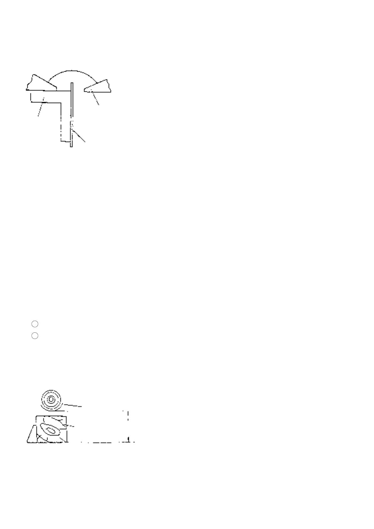
Next, as illustrasted in Fig. 3, place a square so that it is flush against
the side surface of the Saw Blade (or dummy disc), and move the Fence
[32] as necessary so that it is at an exact right angle in relation to the
Saw Blade (or dummy disc). Finally, tighten the two M6 x 30 Bolts
(w/Washers) [31] to fix the Fence [32] in position.
*Dummy Disc: A dummy disc is a toothless disc with the same external
diameter as a saw blade, and is used to perform accuracy inspections
and adjustments.
Fence
Saw Blade
(or dummy disc)
Square
Fig. 3
(2) Adjustment of Saw Blade Lower Limit Position:
When adjusting the lower limit of the Saw Blade, be sure to use a saw blade with an external diameter of
216 mm.
Failure to properly adjust the lower limit position of the Saw Blade may result in the following problems:
1 inability to obtain the maximum cutting capacities of the machine; and
2 there is a danger that the Saw Blade may come in contact with and cut into the Turn Table.
Lower the Saw Blade and confirm without fail that it does not come in contact with the Turn Table. For
adjustment procedures, please refer to Paragraph*, [Confirmation of Saw Blade Lower Limit Positioning].
(3) Adjustment of Saw Blade Height:
Prior to shipment, the Saw Blade height (when fully lowered) is
adjusted so that the dimension from the bottom surface of the Gear
Case and the surface of the Turn Table is between 62.3 mm and
63 mm, as illustrated in Fig. 4.
The operator can adjust the height of the Saw Blade to meet the
needs of the cutting operation. For adjustment procedures, please
refer to Paragraph*, [Confirmation of Saw Blade Lower Limit
Positioning].
Gear Case
Workpiece
62.3 ---
63 mm
Fig. 4
--- 9 ---
(4) Assembly of the Turn Table:
When assembling the Turn Table [35] and the Base [37],
tighten the M6 x 10 Nylock Bolt [40] so that the Turn Table
turns smoothly without excessive play or vibration.
During assembly, liberally apply grease (HI HON KOYU
BC4 is recommended) at the portions marked A in Fig. 5.
Fig. 5
Turn Table
Table Pin
Outer
Circumference
Base
M6 x 10 Nylock Bolt
A
A
A
* Confirmation of Saw Blade Lower Limit Positioning:
Prior to shipment, the lower limit position of
the Saw Blade is factory adjusted so that the
dimension from the bottom surface of the
Gear Case to the surface of the Turn Table is
between 62.3 mm and 63 mm, as illustrated
in Fig. A. The customer should be advised to
confirm that it is properly adjusted prior to
operating the machine. If the lower limit
dimension is not within the designated
amount, there may be cases when the lower
part of the workpiece on the fence side may
not be cleanly cut off.
If adjustment is necessary, turn the lower limit
adjusting M5 x 16 Nylock Bolt [5] located at
the lower right rear part of the Hinge [8] (refer
to the Parts List and exploded assembly
diagram) as necessary to correct the
dimension.
Gear Case
3.23 --- 63 mm
Fig. A
--- 10 ---
1-6. Lubrication:
Advise the customer to lubricate the machine as indicated below at least once a month. Also, prior to applying the
lubrication, any sawdust, dirt or other foreign matter should be thoroughly wiped away with a soft cloth.
(1) Swiveling and Sliding Sections of the Gear Case and Hinge:
Coat machine oil on the swiveling and sliding portions of the Gear Case [51] and Hinge [8].
(2) Vise Assembly Section:
Coat machine oil on the M10 x 66 Knob Bolt [55] portion of the Vise Ass'y [53].
1-7. Machine Accuracy:
On completion of assembly, confirm that machine accuracy is within the standards listed below.
1-8. Cutting Accuracy:
Prepare appropriate test workpieces, cut them as described, and measure cutting accuracy with a square or other
standard measuring device to ensure they are within listed tolerances.
[CAUTION]
Test Workpieces should be prepared with a planer or jointer, and their dimensions and accuracy should
be carefully checked prior to cutting tests. Test workpieces which are manually and/or inaccurately
prepared are useless to check the cutting accuracy of the Model C 8FC.
(1) Press Cutting:
Cutting Conditions:
1 Test Workpiece: Yellow Pine, 60 mm square ... All surfaces squarely planed.
Yellow Pine, H 60 mm x W 100 mm ... All surfaces squarely planed.
2 Saw Blade: 216 mm TCT Saw Blade, No. of Teeth: 24 (Code No. 998859)
3 Cutting Time: 0 Degree (Press Cutting) ... 5 sec. in direction A , 7 sec. in direction B .
45 Degrees (Bevel Cutting) ... 5 sec. in direction A .
4 Measuring Points:
Item
Deflection of Saw Blade (or dummy disc)
Perpendicularity between Base and Fence
Flatness of Fence Surface
Perpendicularity between Saw Blade (or dummy disc) and
Fence
Perpendicularity between Saw Blade (or dummy disc) and Turn
Table
Accuracy (mm)
0.15/200
0.1/40
0.1
0.15/100
0.15/100
A
B
Fence Contacting Surface
Cut Surface
Turn Table Contacting Surface
Square
Fig. 6
--- 11 ---
5 Cutting Accuracy:
[Direction A ]
Workpiece
Square
60 mm
δ
Accuracy
Angle
45˚
0.15 or less
0.15 or less
δ (mm)
[Direction B ]
Workpiece
Square
60 mm
δ
Accuracy
Angle
0.2 or less
δ (mm)
(2) Bevel Cutting:
Cutting Conditions:
1 Test Workpiece: Yellow Pine, H 45 mm x W 60 mm ... All surfaces squarely planed.
2 Saw Blade: 216 mm TCT Saw Blade, 24 teeth (Code NO. 998859)
3 Cutting Time: 9 sec.
4 Cutting Accuracy:
[Direction A ]
Fig. 7
Workpiece
Angle Gauge
45 mm
δ
Accuracy
Angle
45˚ 0.17 or less
δ (mm)
45˚
[Direction B ]
Workpiece
Square
δ
Accuracy
Angle
Fence Contact-
ing Surface
0.13 or less
δ (mm)
Fig. 8
Fence Contacting Surface
Cut Surface
[CAUTION]
If the test workpiece has uneven surfaces, the cutting surface
obtained through bevel cutting will also clearly be uneven.
Therefore, it is particularly necessary to carefully measure
and check the test workpiece before performing the cutting
test. Test workpieces which are cut with a bandsaw are
particularly likely to have uneven surfaces.
Workpiece
Uneven ridgelines
appear
--- 12 ---
2. TROUBLE SHOOTING AND REPAIR GUIDE:
The circled numbers in the table below correspond to the item numbers in the Parts List and exploded assembly
diagrams. All dimensions shown in the table are in millimeters (mm).
Item Phenomenon Possible Cause (s)
Factory Standard
Inspection, Repair, Adjustment
1.
Inaccurate cutting.
... Incaccurate perpen-
dicularity of cut surface
... Improper cutting stop
position
a. Inaccurate
perpendicularity
between the Turn
Table and Saw Blade
will cause the Saw
Blade to cut into the
workpiece at an angle.
b. Excessive deflection
of the Saw Blade.
(Excessive vibration)
c. inaccurate
perpendicularity
between Fence and
Saw Blade.
d. Inaccurate surface
flatness of Fence
causes workpiece to
move irregularly,
causing poor
perpendicularity of cut
surface.
e. Inaccurate surface
flatness of the Turn
Table.
f. Inaccurate
perpendicularity
between the Fence
and the Turn Table
and/or Base causes
inaccurate cutting
during miter cutting.
g. Excessive
misalignment of the
Base and the Turn
Table causes the Saw
Blade to cut into the
workpiece at an angle.
0.15/100
(based on
dummy disc
alignment)
(see Fig. 9)
0.15/200
(based on
dummy disc
alignment)
0.15/100
(see Fig. 10)
0.1 or less
(see Fig. 11)
0.1 or less
0.1/40
(see Fig. 12)
0.1
0.2
(see Fig. 13)
Readjust perpendicularity with
the M5 x 16 Nylock Bolt [5].
Check if the M5 x 10 Hex.
Socket Set Screw [15] which
fixes the Gear Case Pin [41]
is loose. Tighten if necessary.
Check for deformation of the
Hinge [8], Hinge Holder [15],
Gear Case [51], and Turn
Table [35]. Replace as
necessary.
Replace the Saw Blade [100].
Check for damage on Washer
(C) [99] and Washer (C)
[101]. Smooth minor defects
with a file.
Replace Washer (C) [99] and
[101].
Check if the M6 x 30 Bolts
(w/Washers) [31] are loose.
Tighten if necessary.
Replace the Fence [32].
Replace the Turn Table [35].
Replace the Fence [32].
Check for looseness of the
M6 x 10 Nylock Bolt [40]
which fixes the Turn Table
[35]. Adjust as necessary.
Replace the Base [37] and/or
Turn Table [35] if deformed.
Perpendicularity
0.15/100
Fig. 9
Fig. 10
Fig. 11
Fig. 12
0.1 or less
Saw Blade
Fence
Turn Table
Fence
Perpendicularity
0.15/100
Saw Blade
0.1 or less
Fence
Fence
Perpendicularity
0.1/40
Fig. 13
Turn Table
Base
+
--
+
--
--- 13 ---
Washer (C)
Fig. 14
Washer (C)
A
A
Item Phenomenon Possible Cause (s)
Factory Standard
Inspection, Repair, Adjustment
1
2
Poor Cutting Accuracy
Rough Cut Surface
Parallelism A = 0.02/44
h. The swivel portions of
the Hinge and Gear
Case are either loose
and move with
excessive play, or fail
to move smoothly
because of excessive
fricton. This causes
unwanted movement
of the Gear Case,
applies excessive
pressure on parts, and
causes deformation of
various components.
i. Excessively fast
cutting operation
causes deflection of
the Saw Blade, and
reduces cutting
accuracy.
j. Excessive pressure is
applied during cutting
due to a dull or
damaged Saw Blade.
k. The workpiece is
warped, bent or
deformed, causing it
to slip during cutting.
a. Excessive deflection
of the Saw Blade.
(Excessive deflection
causes rought cutting
surface.)
b. Damage of Washers
(C) causes inaccurate
parallelism.
c. Inaccurate
perpendicularity
between the Turn
Table and the Saw
Blade causes the Saw
Blade to cut through
the workpiece at a
slight angle, causing a
rough cutting surface.
----
----
----
----
0.15/200
(Based on
dummy disc
alignment)
0.02/44
(see Fig. 14)
0.15/100
(Based on
dummy disc
alignment)
(see Fig. 9)
Check for foreign matter
(cutting chips, etc.) in the
fittings of the Hinge [8], Gear
Case [51], and Gear Case Pin
[41]. Remove as necessary.
Check if the M5 x 10 Hex.
Socket Set Screw [16] which
fixes the Gear Case Pin [41]
is loose.
Tighten as necessary.
Reduce cutting speed.
(For a 60 mm-square
workpiece, the cutting
operation should be from 6 to
9 seconds.)
Resharpen or replace the Saw
Blade.
Remove the defects from the
workpiece with a planer, and
cut it again.
Same as Item 1-b.
Repair damage on Washers
(C) [99] and [101], or replace
them if beyond repair.
Same as 1-a.
--- 14 ---
Item Phenomenon Possible Cause (s)
Factory Standard
Inspection, Repair, Adjustment
2
3
Poor Cutting Accuracy
Saw Blade is locked.
d. Cutting operation
speed is too fast.
e. Workpiece is not fixed
securely.
f. The Turn Table is not
securely fixed with the
knob bolt.
g. The swivel portions of
the Hinge and Gear
Case are either loose
and move with
excessive play, of fail
to move smoothly
because of excessive
friction.
h. The workpiece is
warped, bent or
deformed, making it
difficult to cut.
i. Excessive machine
vibration.
a. Excessively fast
cutting speed.
b. The sectional area of
the extension cord is
too small.
c. Excessive pressure is
applied during cutting
due to a dull or
damaged Saw Blade.
d. An improper Saw
Blade is being used.
e. The workpiece is
warped of deformed,
causing the Saw
Blade to bind during
the cutting operation.
----
----
----
----
----
----
----
----
----
----
----
Reduce the cutting speed.
Firmly fix the workpiece with
the Vise Ass'y.
Before the cutting operation,
securely fix the Turn Table
[35] without fail with the M6 x
37 Knob Bolt [27].
Same as Item 1-h.
Remove the defects from the
workpiece with a planer.
Check Possible Causes a, b,
f, and g.
Reduce the cutting speed.
Use a larger diameter and/or
shorter extension cord.
Resharpen or replace the Saw
Blade.
Use a genuine HITACHI TCT
Saw Blade.
The greater the number of
teeth on the Saw Blade, the
greater is the cutting
resistance. When using a
Saw Blade with a large
number of teeth, the cutting
operation should be
performed at a slower speed.
Remove the defects from the
workpiece with a planer.
  • Page 1 1
  • Page 2 2
  • Page 3 3
  • Page 4 4
  • Page 5 5
  • Page 6 6
  • Page 7 7
  • Page 8 8
  • Page 9 9
  • Page 10 10
  • Page 11 11
  • Page 12 12
  • Page 13 13
  • Page 14 14

Hitachi C 8FC User manual

Type
User manual

Hitachi C 8FC is a versatile power tool designed for precise cutting and mitering applications. Its powerful motor and sturdy construction make it suitable for various tasks, including wood, plastic, and metal cutting. The C 8FC features a durable saw blade that delivers clean and accurate cuts, along with an adjustable fence for precise angle measurements. It also has a user-friendly design with a comfortable grip and easy-to-use controls. Additionally, the C 8FC's compact size and lightweight design allow for easy handling and storage.

Ask a question and I''ll find the answer in the document

Finding information in a document is now easier with AI