ALTA R Series Roller Shades User manual

Type
User manual
ROLLER SHADES
R-Series
Thank you for your purchase. This shade has been custom built for you from the highest quality materials.
To avoid errors and save valuable time, please read these instructions before installing your new shade.
1. Pencil or Marker
2. Measuring Tape
3. Phillips Screwdriver
4. Level
5. Power Drill
7. Mounting Fasteners
1
Table of Contents Continued ........................................................................................................................................................................... Page 2
Getting Started ................................................................................................................................................................................................ Page 2
INSIDE MOUNT
Shades with No Top Treatment ........................................................................................................................................................................ Page 3
Shades with Square Cassette ......................................................................................................................................................................... Page 3
Shades with Curved Cassette ......................................................................................................................................................................... Page 4
Shades with 3” Fascia ..................................................................................................................................................................................... Page 5
Shades with 4” Fascia .................................................................................................................................................................................. Page 6-7
Shades with Pocket ...................................................................................................................................................................................... Page 8-9
Shaded with Fabric Cornice .......................................................................................................................................................................... Page 10
Shaded with Deluxe Valance .......................................................................................................................................................................... Page 10
OUTSIDE MOUNT
Shades with No Top Treatment .......................................................................................................................................................................Page 11
Shades with Square Cassette ........................................................................................................................................................................Page 11
Shades with Curved Cassette ....................................................................................................................................................................... Page 12
Shades with 3” Fascia ................................................................................................................................................................................... Page 13
Shades with 4” Fascia .............................................................................................................................................................................. Page 14-15
Shades with Pocket .................................................................................................................................................................................. Page 16-17
Shades with Fabric Cornice ....................................................................................................................................................................... Page 18-19
Installing Deluxe Valance ............................................................................................................................................................................... Page 19
TABLE OF CONTENTS
Mounting Surface Fastener
Drywall, Plaster Wall Anchors, Expansion Bolts
(Not provided)
Metal Sheet Metal Screws
(Not provided)
Wood No. 6 Hex Head Screws
(Provided)
INSTALLATION INSTRUCTIONS
TOOLS YOU WILL NEED
Required installation components are wrapped in your package along with these instructions.
NOTE: Some parts may vary depending on the selected mounting options or control system options and whether intermediate brackets are required.
Motorized Shades .......................................................................................................................................................................................... Page 19
Straightening the Shade ................................................................................................................................................................................ Page 20
Care and Cleaning ......................................................................................................................................................................................... Page 20
Child Safety ................................................................................................................................................................................................... Page 20
TABLE OF CONTENTS
2
With proper installation, operation, and care, your new shades will provide years of beauty and performance. Please thoroughly review this instruction
booklet before beginning the installation. If the installation brackets are mounted correctly, the rest of the installation process will follow easily.
Make sure mounting surface is level. Brackets must be in line and level. Shim brackets if necessary.
The head rail must be level for the shade to operate properly.
Once the brackets are secured and level, the fabric roll can be inserted. Make sure your hands are clean to avoid soiling the fabric.
Shades with
No Top Treatment — Standard
Cassette
Curved Cassette Square Cassette
Deluxe Valance Fabric Cornice
3” Fascia and 4” Fascia Pocket
#8 x 1/4”
Hex Head Screw
#8 x 3/8” Phillips Pan
Thread Forming Screw
#8 x 1/2”
Carriage Bolt
#8 Lock Nut
Inside Mount: Screws Only
Outside Mount: Screws & Brackets
Outside Mount
Bracket
Inside/Ceiling
Mount Bracket
Small Medium/Large
Slotted Angle Bracket
Bracket
GETTING STARTED
1. Measure correct spacing, mark the desired location
2. Install brackets – Brackets must be in line and level. Shim brackets if necessary.
Follow image below:
1. Hook cassette onto the bracket
2. Push the cassette towards the back
3. Allow the hook at the back of the cassette
to engage securely onto the hook at the
rear of the bracket.
To Remove the shade:
Reverse the steps above.
3
All Operating Systems
Determine the control side. Bracket (B) with tab (foot) should be at the control side and the bracket (A) with V slot and T-Hook should be at
the idler side.
The installation brackets are always mounted so that the inner surfaces face each other. Make sure all brackets are leveled and aligned.
• Insert control side into the foot of the bracket.
Set the post of the idler end into the V slot of the idler side bracket. Rotate the T-hook on the idler side bracket over the post to lock in the
post and secure the fabric roll.
Flush Mounting Depth Requirement: 3-3/4”
Min. Mounting Surface Height Requirement: 1-1/2”
End Cap (attached at factory)
Flush Mount Depth Requirement: 1-1/4”
Min. Mounting Depth Requirement: 1-1/2”
1-1/2”
Control Side
Idler Side
V Slot
T-Hook Front
(B)
(A)
Shades with Square Cassette — INSIDE MOUNT
Shades with No Top Treatment — INSIDE MOUNT
1. Space brackets evenly. Using the installation bracket as a template, measure to the center of the brackets and mark the hole locations
with a pencil for drilling.
2. Install the brackets, make sure all brackets are leveled and aligned. Mount the shade.
Small Cassette
Figure A - Position the cassette valance so that the ridge engages into the top lip of all brackets.
Figure B - Rotate the bottom front of the cassette valance upwards until the rear of the cassette
valance engages into the bracket and snaps into place, as shown.
To remove the shade
Hold the cassette at each bracket tab to disengage the rear of the cassette.
Medium/Large Cassette
Figure A - Position and securely engage rear of the cassette into the bottom hooks of the bracket.
Rotate cassette upward (1) and push backward (2).
Figure B - Hold the cassette release gently (3) to ensure the top of the cassette engaging into
the top lips of all brackets, as shown.
To remove the shade
Hold the cassette, gently insert a athead screwdriver in between the top of the cassette
and each bracket tab to assist in releasing the cassette from the top bracket lips. Push the
cassette toward the back. Rotate downward to disengage the cassette.
Shades with Curved Cassette — INSIDE MOUNT
4
Flush Mounting Depth Requirement:
2-7/8” (small curved cassette)
3-3/4” (medium curved cassette)
4-3/8” (large curved cassette)
Min. Mounting Depth Requirement: 1-1/2”
Release Tab
Release Tab
Hooks
The open end of each bracket faces downward, as shown in the image. The bracket with a tab (foot) in the middle should be at the control side
and the bracket with V slot and T-Hook should be at the idler side.
Install each bracket with two screws through the top.
Make sure all brackets are level and aligned.
INSTALL THE SHADE
1. Insert control side of the fabric roll into the tab (foot) in the
middle of the bracket.
2. Set the post of the idler end into the V slot of the idler side bracket.
Rotate the T-hook over the post on the idler side bracket to lock in
the post and secure the fabric roll.
ATTACH THE FASCIA
Please note, do not install fascia panel until shade is installed. Then assemble the two end brackets and the fascia panel.
Place the top of the fascia panel into the top indention of the brackets. Rotate the panel down and snap it into place.
Shades with 3” Fascia — INSIDE MOUNT
5
Flush Mount Depth Requirement: 3-1/8”
Min. Mounting Depth Requirement: 2-7/8”
Fascia
Panel Rotator - Side
Bracket
The open end of each bracket faces downward, as shown in the image. The bracket with a tab (foot) in the middle should be at the control side
and the bracket with V slot and T-Hook should be at the idler side.
Install each bracket with two screws through the top.
Make sure all brackets are level and aligned.
NOTE: If shade is ordered with Side and/or Bottom Channel, please refer to
Side/Bottom Channel Installation
Instructions.
INSTALL THE SHADE
1. Insert control side of the fabric roll into the tab (foot) in the middle of the bracket.
2. Set the post of the idler end into the V slot of the idler side bracket. Rotate the T-hook over the post on the idler side bracket to lock
in the post and secure the fabric roll.
ATTACH THE FASCIA
3. Place the top of the fascia panel into the top indention of the brackets. Rotate the panel down and snap it into place.
See Side/Bottom Channel Installation Instructions on page 7.
6
Flush Mount Depth Requirement: 4-3/8”
Min. Mounting Depth Requirement: 3-7/8”
Shades with 4” Fascia — INSIDE MOUNT
Side/Bottom Channel Installation Instructions
MOUNT BACK SIDE CHANNELS
1. Align back channel under corner of fascia bracket so the side of the back channel is ush
with the bracket
2. Mark mounting screw hole locations with a center punch
3. Pre-drill holes in the side of channels using metal drill bit
4. Re-align the back channel. Use a level to ensure side channels are straight and leveled.
5. Mount with the correct mounting screws.
INSTALL THE SHADE
1. Insert control side of the fabric roll into the tab (foot) in the middle of the bracket.
2. Set the post of the idler end into the V-slot of the idler side bracket. Rotate the T-hook over the post on the idler side bracket to lock
in the post and secure the fabric roll.
INSTALL FRONT SIDE CHANNEL
1. Install front side channel by engaging lip of the channel into the
groove on the back side channel. Snap front side channel into place.
INSTALL BOTTOM CHANNEL (if ordered)
1. Place left side of bottom channel between front and back side channels.
2. Slide the right side down in between the front and back side channels until the bottom
closure sits on the window sill. Mount bottom channel to window sill using mounting screws.
ATTACH FASCIA
1. Control side bracket attaches to the side of the panel with the notch.
The idler side bracket goes on the side without the notch.
2. Place the top of the fascia panel into the top indention of the brackets. Rotate the panel down
and snap it into place.
7
Engage lip into groove Snap into place
Back
Channel
Front
Channel
Front
Channel
Back
Channel
Click
Click
Shades with 4” Fascia — INSIDE MOUNT
INSTALL MOUNTING BRACKETS
1. Insert bracket into the pocket. Attach end plate onto the side bracket.
2. Using appropriate screws, install pocket into top or window frame.
NOTE: If shade is ordered with side and/or bottom channel please go to Side/Bottom Channel Installation Instructions.
If not, skip to Install the Shade.
INSTALL THE SHADE
1. Insert control side of the fabric roll into the tab (foot) in the middle of the control side bracket.
2. Set the post of the idler end into the V slot of the idler side bracket. Rotate the T-hook
over the post on the idler side bracket to lock in the post and secure the fabric roll.
3. Install Bottom Closure into the pocket on an angle.
Once aligned, allow front of bottom closure to drop in place.
See Side/Bottom Channel Installation Instructions on page 9.
8
Flush Mounting Depth Requirement: 4-9/16”
Min. Mounting Depth Requirement: 3-5/8”
Shades with Pocket — INSIDE MOUNT
Side/Bottom Channel Installation Instructions
MOUNT BACK SIDE CHANNELS
Mount Back Side Channels by aligning the back channel ush with the back of the pocket and mount with the correct mounting screws.
INSTALL THE SHADE
To install the shade, insert control side rst by placing the hole in the core into the tab (foot) in the middle of the bracket. Set the post of the
idler end into the V slot of the idler side bracket. Rotate the T-hook over the post on the idler side bracket to lock in the post and secure
the fabric roll.
INSTALL FRONT SIDE CHANNEL
Install Front Side Channel by engaging lip of channel into the groove on the back side channel. Snap front side channel into place.
INSTALL BOTTOM CHANNEL (if ordered)
To install Bottom Channel (if ordered), place left side of bottom channel between front and back side channels. Slide the right side down
in between the front and back side channels until the bottom closure sits on the window sill. Mount bottom channel to window sill using
correct mounting screws.
Install Bottom Closure into the pocket on an angle. Once aligned, allow front of bottom closure to drop in place.
9
Engage lip into groove Snap into place
Front
Channel
Back
Channel
Front
Channel
Back
Channel
Shades with Pocket — INSIDE MOUNT
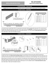
MOUNT THE CORNICE
1. Center the cornice in desired location.
2. Mark 2” from each jamb for screw location. Mark the mounting surface using a pencil. Center the marks in the bracket slots.
Space screws evenly, but no more than 24” apart.
3. Drill screw holes.
IMPORTANT: Use drywall anchors when mounting into drywall.
4. Install the cornice through the slotted angle bracket to the
mounting surface with the #8 x 1-1/4” screws provided.
To install shade behind the cornice – refer to instruction under No Top Treatment
Install the valance rst and then proceed with shade installation.
The valance can be mounted directly with the provided installation screws, drill vertically through the pre-drilled slots
into the top of the window frame.
To install shade behind the valance – refer to instruction under No Top Treatment.
10
Slotted Angle
Bracket
Slotted Angle
Bracket
Cornice not
shown for
clarity
Inside Mount Screws Required
Width # of Screws
12” – 28” 3
28-1/8” – 52” 4
52-1/8” – 76” 5
76-1/8” – 100” 6
100-1/8” – 120” 7
120-1/8” – 144” 8
Space Evenly Space Evenly
Jamb Jamb
At least 2” At least 2”
Slotted
Angle
Flush Mount Depth Requirement: 1-1/2”
Min. Mounting Depth Requirement: 1”
Flush Mount Depth Requirement: 3-1/8”
Min. Mounting Depth Requirement: 1-1/4”
Shades with Fabric Cornice — INSIDE MOUNT
Shades with Deluxe Valance — INSIDE MOUNT
11
All Operating Systems
Determine the control side. Bracket (B) with tab (foot) should be at the control side and the bracket (A) with V slot
and T-Hook should be at the idler side.
The installation brackets are always mounted so that the inner surfaces face each other. Make sure all brackets are leveled and aligned.
• Insert control side into the foot of the bracket.
Set the post of the idler end into the V slot of the idler side bracket. Rotate the T-hook on the idler side bracket over the post to lock in the
post and secure the fabric roll.
Measure correct spacing
Install brackets – face x wall mount, top x ceiling mount.
Brackets must be in line and level.
Shim brackets if necessary.
To Remove the shade:
Reverse the steps above.
Min. Mounting Surface Height Requirement: 1-3/4”
Min. Mounting Surface Height Requirement: 4”
End Cap (attached at factory)
V Slot Tab
(Foot)
(A)
(B)
Shades with Square Cassette — OUTSIDE MOUNT
Shades with No Top Treatment — OUTSIDE MOUNT
Small Cassette
Figure A - Position the cassette valance so the ridge engages into the top lip of all brackets.
Figure B - Rotate the bottom front of the cassette valance upwards and towards the bracket
until the rear of the cassette valance engages into the bracket and snaps into place, as shown.
To remove the shade
Hold the cassette at each bracket tab to disengage the rear of the cassette.
Medium/Large Cassette
Space brackets evenly. Using the installation bracket as a template, measure to the center
of the brackets and mark the hole locations with a pencil for drilling.
Install the brackets, make sure all brackets are leveled. Mount the shade.
Figure A - Position and securely engage rear of the cassette into the bottom hooks of the bracket.
Rotate cassette upward (1) and push backward (2).
Figure B - Hold the cassette release gently (3) to ensure the top of the cassette engaging into
the top lips of all brackets, as shown.
To remove the shade
Hold the cassette, gently insert a athead screwdriver in between the top of the cassette
and each bracket tab to assist in releasing the cassette from the top bracket lips.
Push the cassette toward the back. Rotate downward to disengage the cassette.
12
Min. Mounting Surface Height Requirement:
2-3/4” (small curved cassette)
3-1/8” (medium curved cassette)
4” (large curved cassette)
Release Tab
Release Tab
Shades with Curved Cassette — OUTSIDE MOUNT
INSTALL THE MOUNTING BRACKETS
The open end of each bracket faces downward, as shown in the image.
Attach each bracket to the mounting surface using the two holes in the rear of each bracket.
Use a level to make sure brackets are leveled.
INSTALL THE SHADE
Insert control side of the fabric roll into the tab (foot) in the middle of the bracket.
Set the post of the idler end into the V slot of the idler side bracket.
Rotate the T-hook on the idler side bracket to lock in the post and secure the fabric roll
INSTALL THE FASCIA
Please note, do not install fascia panel until shade is installed. Then assemble the two end brackets and the fascia panel.
Place the top of the fascia panel into the top indention of the brackets. Rotate the panel down and snap it into place.
Attach bracket end plate to the brackets.
1313
Min. Mounting Depth Requirement: 3”
Fascia
Panel Rotator - Side
Bracket
Tab
Top/Rear Cover
Removed for Clarity
Shades with 3” Fascia — OUTSIDE MOUNT
INSTALL THE MOUNTING BRACKETS
The open end of each bracket faces downward, as shown in the image. The bracket with a tab (foot) in the middle should be at the control side
and the bracket with V slot and T-Hook should be at the idler side.
Mount brackets to the wall using the two holes in the rear of each bracket for wall mount. For ceiling mount, mount brackets
to the ceiling using two holes in the top of each bracket.
Use a level to make sure brackets are leveled.
NOTE: If shade is ordered with Side and/or Bottom Channel, please refer to Side/Bottom Channel Installation Instructions.
INSTALL THE SHADE
1. Insert control side of the fabric roll into the tab (foot) in the middle of the bracket.
2. Set the post of the idler end into the V slot of the idler side bracket. Rotate the T-hook over the post on the idler side bracket to lock
in the post and secure the fabric roll.
ATTACH THE FASCIA
3. Place the top of the fascia panel into the top indention of the brackets. Rotate the panel down and snap it into place.
See Side/Bottom Channel Installation Instructions on page 15
14
Min. Mounting Depth Requirement: 4” Tab
Top/Rear Cover
Removed for Clarity
Shades with 4” Fascia — OUTSIDE MOUNT
Side/Bottom Channel Installation Instructions
MOUNT BACK SIDE CHANNELS
1. Align back channel under corner of fascia bracket so the side of the back channel
is ush with the bracket.
2. Mark mounting screw hole locations with a center punch
3. Pre-drill holes in the side of channels using metal drill bit as shown.
4. Re-align the back channel. Use a level to ensure side channels are straight and leveled.
5. Mount with the correct mounting screws.
INSTALL THE SHADE
1. Insert control side of the fabric roll into the foot of the control side bracket.
2. Set the post of the idler end into the V slot of the idler side bracket. Rotate the T-hook over the post on the idler side bracket to lock
in the post and secure the fabric roll.
INSTALL FRONT SIDE CHANNEL
1. Install front side channel by engaging lip of the channel into the groove
on the back side channel. Snap front side channel into place.
INSTALL BOTTOM CHANNEL (if ordered)
1. Place left side of bottom channel between front and back side channels.
2. Slide the right side down in between the front and back side channels until bottom
closure is at the bottom of the side channels. White holding the bottom channel in
place, drill a screw hole using a metal drill bit (1” from the side and 3/8” from bottom
corner). Install mounting screw through all channels and into the wall.
ATTACH FASCIA
1. The control-side bracket attaches to the side of the panel with the notch. The rotator side bracket
goes on the side without the notch.
2. Place the top of the fascia panel into the top indention of the brackets. Rotate the panel down
and snap it into place.
3. Attach bracket end plate to the brackets.
1515
Engage lip into groove Snap into place
Back
Channel
Front
Channel
Front
Channel
Back
Channel
1” from side
3/8” from bottom
Click
Click
Shades with 4” Fascia — OUTSIDE MOUNT
16
INSTALL POCKET & MOUNTING BRACKETS
1. Mount pocket to ceiling using the appropriate mounting screws.
2. Pre-drill mounting holes, and use anchor if needed.
3. Make sure all brackets are level.
4. Insert bracket into the pocket (use mallet to gently tap bracket into place)
until ush with the end of the pocket. Secure bracket to pocket with
supplied mounting screws.
5. Secure end plate to the pocket
NOTE: If shade is ordered with side and/or bottom channel please go to Side/Bottom Channel Installation Instructions.
If not, skip to shade installation.
INSTALL THE SHADE
1. Insert control side of the fabric roll into the tab (foot) in the middle of the control side bracket.
2.Set the post of the idler end into the V slot of the idler side bracket. Rotate the T-hook
over the post on the idler side bracket to lock in the post and secure the fabric roll.
3. Install Bottom Closure into the pocket on an angle.
Once aligned, allow front of bottom closure to drop in place.
See Side/Bottom Channel Installation Instructions on page 17.
Min. Mounting Surface Height Requirement: 4-1/2”
Shades with Pocket — CEILING MOUNT
17
Side/Bottom Channel Installation Instructions
MOUNT BACK SIDE CHANNELS
1. Align back channel under corner of fascia bracket so the side of the back channel
is ush with the bracket.
2. Mark mounting screw hole locations with a center punch.
3. Pre-drill holes in the side of channels using metal drill bit as shown.
4. Re-align the back channel. Use a level to ensure side channels are straight and leveled.
5. Mount with the correct mounting screws.
INSTALL THE SHADE
1. Insert control side of the fabric roll into the tab (foot) in the middle of the control side bracket.
2. Set the post of the idler end into the V slot of the idler side bracket.
Rotate the T-hook over the post on the idler side bracket to lock in the post
and secure the fabric roll.
INSTALL FRONT SIDE CHANNEL
1. Install front side channel by engaging lip of the channel into the
groove on the back side channel. Snap front side channel into place.
INSTALL BOTTOM CHANNEL (if ordered)
1. Place left side of bottom channel between front and back side channels.
2. Slide the right side down in between the front and back side channels until bottom closure is at the bottom of the side channels.
White holding the bottom channel in place, drill a screw hole using a metal drill bit (1” from the side and 3/8” from bottom corner).
Install mounting screw through all channels and into the wall.
3. Install Bottom Closure into the pocket on an angle. Once aligned, allow front of bottom closure to drop in place.
1” from side
3/8” from bottom
Engage lip into groove Snap into place
Back
Channel
Front
Channel
Front
Channel
Back
Channel
Shades with Pocket — OUTSIDE MOUNT
1. Attach the returns to the cornice.
Check the angle on each return.
Fasten screws into the cornice.
Repeat for opposite return.
2. Skip to next step if ordered with a shade. If ordered custom returns under Fabric Cornice Only
(without shade), place the 8” bracket on top of the slotted angle next to the return. With the back
of the bracket ush with the back edge of the return, mark the cut mark just past the screw hole
that lines up with the slotted angle. Then cut the bracket at the mark.
3. Measure distance from top edge of cornice to the rst complete hole in the slotted angle. Use that measurement to mark the location
for the rst bracket at the desired height. Repeat for the opposite bracket.
Space brackets evenly, but no more than 24” apart.
4. Drill the screw holes. (Use drywall anchors when needed)
5. Attach the installation brackets with the screws provided.
Ensure the mounting surface is level and the brackets are aligned. Shim brackets, if needed.
6. Using the bolts and nuts provided, attach the slotted angle on top of the installation brackets
See Install the Dust Cover (Outside Mount Only) on page 19.
Shades with Fabric Cornice — OUTSIDE MOUNT
18
Return
(Outside Mount Only)
Installation Bracket
(Outside Mount Only)
Slotted
Angle
Bracket
Bolt &
Nut
Dust Cover
Support
Dust Cover
Outside Mount Screws Required
Width # of Screws
12” – 28” 2
28-1/8” – 52” 3
52-1/8” – 76” 4
76-1/8” – 100” 5
100-1/8” – 120” 6
120-1/8” – 144” 7
Min. Mounting Surface Height Requirement: 2”
Space Evenly Space Evenly
Measure
this distance
Bracket
Measure
this distance
Measure
this distance
Bracket Use the distance measured
in the previous step.
Cornice not
shown for
clarify
Mark/Cut
This Line
Install the Dust Cover (Outside Mount Only)
Dust cover only comes with cornice 1-1/2”, 4” & 6” return.
7/8” Dust Cover
Remove adhesive backing from square tapes
Place the square tapes on slotted angle
Put the dust cover on top of slotted angle and press it to secure the adhesive.
3-7/8” & 5-7/8” Dust Cover
Snap the dust cover support onto the slotted angle as shown
Remove adhesive backing from square tapes
Place the square tapes on slotted angle and brackets
Press the dust cover in place to secure the adhesive
To install shade behind the cornice – refer to instruction under No Top Treatment.
1. Install the valance rst and then proceed with shade installation.
2. Use anchors if needed, spaced brackets evenly. Using the installation bracket as a template, measure to the center of the brackets
and mark the hole locations with a pencil for drilling.
3. Brackets must be in line and level. Shim brackets if necessary.
4. Mount the brackets with the screws provided, slide the valance under the clips that are on the top of the installation brackets.
To install shade behind the valance – refer to instruction under No Top Treatment.
19
Refer to motorization programming instructions provided for more details.
Dust
Cover
Dust
Cover
Press
Snap support
onto slotted angle.
Dust Cover
Support
Slotted
Angle Tape
Squares
Dust Cover
Support Tape
Squares
Dust Cover
Remove adhesive
backing from
both sides.
Peel
Min. Mounting Surface Height Requirement: 2”
Remove adhesive
backing from
both sides.
Peel
Shades with Fabric Cornice — OUTSIDE MOUNT
Shades with Deluxe Valance — OUTSIDE MOUNT
Motorized Shades
If your shade does not roll up evenly (telescoping)
First check the mounting brackets are aligned and level. (Please use a leveling device to check)
IF shade STILL does not roll evenly.
Unroll the shade until you can see where the fabric is attached to the roller tube.
Place a small piece of evenly cut masking tape at the opposite end from where the fabric gathers (telescoping).
A second or even third piece can be placed until shade is rolled up evenly.
Roller Shades are made of the highest quality materials for extended wear. If it is not damaged or exposed to a great deal of direct sunlight, it is not
unrealistic to expect years of enjoyment with minimal care. Raising and lowering shades periodically helps reduce most natural dust accumulation.
If additional cleaning is desired, regular dusting with a feather duster or carefully cleaned with a soft vacuum brush attachment.
Fabric: Vacuum your roller shade frequently. This will keep your roller shade looking like new! If your roller shade becomes soiled use a high-quality
foam upholstery cleaner.
Transparent and Vinyl: Transparent and vinyl shades can be readily cleaned with any standard commercial window spray cleaner, which should
be diluted with 10 parts water to 1 part cleaning solution. For best results, shades should be removed from brackets, then placed on a clean, at
covered surface. To prevent streaking and inconsistent drying, wash and dry one small area at a time. Do not rub hard. Use a soft, lint-free cloth for
washing and drying.
20
Immediately remove this product if a cord longer than 22 cm or a loop
exceeding 44 cm around becomes accessible.
Rev 7/21 Print 7/21
WARNING
RISQUE D’ÉTRANGLEMENT–
Les enfants en bas âge
MISE EN GARDE
peuvent s’étrangler avec des cordes. Enlevez immédiatement ce produit si une
corde mesurant plus de 22 cm devient accessible ou si le contour d’une boucle de
plus de 44 cm devient accessible.
STRANGULATION HAZARD –
Young chidren can be strangled by cords.
Straightening the Shade
CHILD SAFETY
CARE AND CLEANING
  • Page 1 1
  • Page 2 2
  • Page 3 3
  • Page 4 4
  • Page 5 5
  • Page 6 6
  • Page 7 7
  • Page 8 8
  • Page 9 9
  • Page 10 10
  • Page 11 11
  • Page 12 12
  • Page 13 13
  • Page 14 14
  • Page 15 15
  • Page 16 16
  • Page 17 17
  • Page 18 18
  • Page 19 19
  • Page 20 20
  • Page 21 21
  • Page 22 22
  • Page 23 23
  • Page 24 24
  • Page 25 25
  • Page 26 26
  • Page 27 27
  • Page 28 28
  • Page 29 29
  • Page 30 30
  • Page 31 31
  • Page 32 32
  • Page 33 33
  • Page 34 34
  • Page 35 35
  • Page 36 36
  • Page 37 37
  • Page 38 38
  • Page 39 39
  • Page 40 40

ALTA R Series Roller Shades User manual

Type
User manual

Ask a question and I''ll find the answer in the document

Finding information in a document is now easier with AI

in other languages