FOLD ON DOTTED LINE
(1/8")
DRILL 3.2mm HOLE
(2 PLACES)
PLACE AGAINST DOOR
(11/16")
DRILL 16mm HOLE
TEMPLATE
PLACE AGAINST JAMB
OPPOSITE HINGES FOR
L.H.R. DOOR INSTALLATION
PLACE AGAINST HEADER
185mm ARMATURE PLATE GUIDE PIN HOLE
[6mm(1/4") DIA, 12.5mm(1/2") DEEP]
185mm ARMATURE PLATE
[6mm(1/4") DIA, 12.5mm(1/2") DEEP]
PLACE AGAINST JAMB
OPPOSITE HINGES FOR
R.H.R. DOOR INSTALLATION
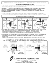
STEP 1
FOLD TEMPLATE ALONG DOTTED LINE.
PLACE TEMPLATE AGAINST DOOR AND HEAD FRAME.
DRILL HOLES AS INDICATED ON TEMPLATE.
STEP 2
MOUNT THE ARMATURE PLATE TO DOOR USING
1 RUBBER WASHER SANDWICHED BETWEEN 2 STEEL
WASHER (THE RUBBER WASHER AND 2 STEEL
WASHER ARE INSTALLED ON THE THROUGH SEXNUT
BETWEEN THE ARMATURE PLATE AND DOOR).
●
●
●
●
STEP 3
DETACH MOUNTING PLATE FROM MAGNET BY REMOVING
2 SOCKET CAP SCREWS. SCREWS COULD BE ACCESSED
THROUGH BOTTOM OF MAGNET.
●
●INSTALL THE MOUNTING PLATE WITH 2 FLAT HEAD
SCREWS (THE 2 M5x15 FLAT HEAD SCREWS ARE
INSTALLED IN THE SLOTTED HOLES FOR ADJUSTMENT).
ADJUST MOUNTING PLATE SO THAT IT FORMS A RIGHT
ANGLE WITH THE ARMATURE PLATE.
●
●USING THE MOUNTING PLATE AS A TEMPLATE,DRILL
THE WIRE HOLE.
●DRILL AND INSTALL THE REMAINING MOUNTING SCREWS.
STEP 4
INSTALL MAGNET TO MOUNTING PLATE WITH
2 M6 SCREWS SUPPLIED.
●
INSTALL ELECTRICAL WIRING PER
INSTRUCTION SHEET.
●
STEP 5
TEST ALL FUNCTIONS OF THIS MODEL (SEE
WIRING INSTRUCTION).
●
STEP 6
INSERT 2 LOCKING STOPPERS IN TWO END
PLATES,AND COVER WITH 4 mm SCREWS.
●
STEP 7
INSERT 2 ALUMINUM CAPS TO COVER THE
TWO M6 SCREW HOLES.
●
STEP 8
NOTE: IF NEEDED, USE SMALL MAGNET TO
REMOVE LOCKING STOPPERS FROM HOLES.
●
DWG. NO. 820001
75.5367.11 MAGLOCKS 1200lb 20220829 Page 2 of 5
5Handle the equipment with care. Damaging the mating surfaces of the magnet and armature plate may reduce locking efciency.
5The MAGLCOK mounts rigidly to the door frame. The armature plate mounts to the door with the hardware provided. This allows the armature plate to pivot about its
center to compensate for door wear and misalignment.
5You must only use the template with the door in its normally closed position.
5Add threadlocker to all screws before installing, and rmly tighten screws.
5Install only for indoor, dry applications.
5Installation and wiring must be performed in compliance with ANSI / NFPA 70 / NFPA 101 / CSA C22.1, Canadian Electrical Code, Part I, safety standard for electrical
installations, section 32; and CAN/ULC-S524 installation of re alarm system requirements.
5The MAGLOCK shall be installed within the same room as other equipment and circuitry connecting to the MAGLOCK.
5Wiring must be cased to avoid outer cable damage, affect the insulation distance.
5An electric locking mechanism shall not impair the operation of panic hardware mounted on the door.
5An electric locking mechanism shall not impair the intended operation of an emergency exit.
5Shut off all power going to header before attempting any wiring procedures.
5Maintain a clean and safe environment when working in public areas.
5Constantly be aware of pedestrian trafc around the door area.
5Always stop pedestrian trafc through the doorway when performing tests that may result in unexpected reactions by the door.
5Always check placement of all wiring before powering up to ensure that moving door parts will not catch any wires and cause damage to equipment
or cable insulation.
5Ensure compliance with all applicable safety standards (i.e. ANSI A156.10) upon completion of installation.
DO NOT over-tighten the armature plate.
The rubber washer is designed to allow the armature plate to automatically adjust position for best mating position between the magnet and armature plate.
DOOR FRAME
DOOR FRAME
DOOR FRAME
MAGNET
MAGNET
MAGNET
DOOR
DOOR
DOOR
MOUNTING PLATE
Use the applicable mounting template.
See image of template below.
See User’s Guide 75.5643 for U-bracket
installation (to be used with glass doors).
MOUNTING PLATE L&Z BRACKET
FILLER
ARMATURE PLATE
ARMATURE PLATE
ARMATURE PLATE
Filler L&Z bracket
3 Precautions
4 Installation Notes
5 Installation – Mechanical
Mounting Options
TYPICAL INSTALLATION
!
CAUTION


