Page is loading ...

ALARM CONTROLS CORPORATION
19 BRANDYWINE DRIVE P.O. BOX 280 DEER PARK, NY 11729
WWW.ALARMCONTROLS.COM EMAIL: [email protected]
MODEL 1200D
1200 POUND DOUBLE MAGNETIC LOCK
U.L. LISTED, LISTING NUMBER R16756
1200 POUND MINIMUM HOLDING FORCE, EACH LOCK
MAGNET SIZE 21” L x 2-7/8” H x 1-1/2” W
ARMATURE SIZE 7-1/2” L x 2-3/8” W x 5/8” D EACH
12 OR 24 VOLT DC OPERATION, JUMPER SELECTABLE
CURRENT DRAW 400 MA.@12 VDC, 200 MA.@24 VDC
EACH MAGNET
BI-COLORED STATUS LED, DOOR STATUS SENSOR
BOND SENSOR WITH S.P.D.T. 3A. RELAY CONTACTS
ALL METAL NON-ALUMINUM PARTS ARE PLATED
CLEAR ANODIZED US 28 FINISH STANDARD
DURONIC US 40 FINISH AVAILABLE

SOLID DOOR
ALARM CONTROLS CORPORATION
19 BRANDYWINE DRIVE P.O. BOX 280
DEER PARK, NY 11729
800 645-5538 WWW.ALARMCONTROLS.COM
MAGNETIC LOCK INSTALLATION INSTRUCTIONS
ALARM CONTROLS CORPORATION OFFERS A COMPLETE LINE OF MAGNETIC LOCKS AND ACCESSORY ITEMS
TO ASSIST THE INSTALLER IN MANAGING EVERY APPLICATION.
THE MAGNETIC LOCK IS DESIGNED TO MOUNT TO THE DOOR FRAME ON THE STOP SIDE OF THE DOOR IN A
TYPICAL OUTSWINGING DOOR INSTALLATION,(SEE PAGE 2 FOR INSWINGING DOOR INSTALLATION).
SUFFICIENT HEADER SPACE MUST BE AVAILABLE TO MOUNT THE MAGNETIC LOCK TO INSURE A SAFE AND
SECURE INSTALLATION.
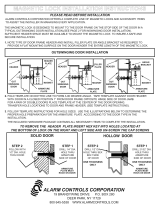
1. NOTE TYPE OF DOOR FRAME HEADER AND INSTALL FILLER PLATE OR ANGLE BRACKET AS REQUIRED TO
PROVIDE A FLAT MOUNTING SURFACE ON THE DOOR HEADER THE ENTIRE LENGTH OF THE MAGNETIC LOCK.
HEADER
HEADER HEADER
OUT
SWINGING
DOOR
OUT
SWINGING
DOOR
OUT
SWINGING
DOOR
MAGNET
MAGNET
FILLER
PLATE
MAGNET
ARMATURE
PLATE
ARMATURE
PLATE
ARMATURE
PLATE
ANGLE
BRACKET
HEADER
PLATE
2. FOLD TEMPLATE ON DOTTED LINE TO FORM A 90 DEGREE ANGLE. TAPE TEMPLATE AGAINST DOOR HEADER
WITH DOOR IN A CLOSED POSITION 1” FROM DOOR FRAME OPPOSITE HINGE SIDE OF DOOR JAMB.
FOR A PAIR OF DOUBLE DOORS PLACE TEMPLATE AT THE CENTER OF THE DOOR OPENING.
TRANSFER HOLE LOCATIONS TO DOOR AND FRAME HEADER, (SEE TEMPLATE INSTRUCTIONS).
3. FOLLOW TEMPLATE INSTRUCTIONS FOR HOLE SIZES. USE THE ILLUSTRATIONS BELOW TO DETERMINE THE
PROPER HOLE PREPARATION FOR THE ARMATURE PLATE ACCCORDING TO THE DOOR TYPE IN THE
INSTALLATION.
THE INCLUDED HARDWARE PACKAGE CONTAINS ALL NECESSARY ITEMS TO COMPLETE THE INSTALLATION.
HOLLOW DOOR
STEP 2
FOLLOW WITH
1/2” DIA. HOLE
THRU DOOR
STEP 1
DRILL 1/4” DIA.
HOLE THRU
ARMATURE
SIDE OF DOOR
STEP 2
DRILL 1/2” DIA.
HOLE THRU SEX
BOLT SIDE
OF DOOR
ONE THICKNESS
ONLY
STEP 1
DRILL 21/32” DIA.
HOLE THRU
ARMATURE
SIDE OF DOOR
ONE THICKNESS
ONLY
OUTSWINGING DOOR INSTALLATION
ARMATURE
PLATE MUST
ROCK ON DOOR
ARMATURE
PLATE MUST
ROCK ON DOOR
PLEASE READ BEFORE INSTALLATION
TO REMOVE THE HEADER PLATE INSERT HEX KEY INTO HOLES LOCATED AT
THE BOTTOM OF LOCK ON THE RIGHT AND LEFT SIDE AND UN-SCREW THE CAP SCREWS

INSWINGING DOOR INSTALLATION WITH L- Z BRACKET
STEP 1
FASTEN THE L BRACKET ON THE DOOR FRAME IN A SUITABLE LOCATION.
MOUNT THE MAGNETIC LOCK TO THE L BRACKET.
MAKE SURE THAT THE MAGNETIC LOCK DOES NOT OBSTRUCT THE
CLOSING OF THE DOOR.
CONNECT THE CORRECT VOLTAGE TO THE MAGNET.
STEP 2
ASSEMBLE THE Z BRACKET WITH THE SOCKET HEAD CAP SCREWS
PROVIDED. DO NOT TIGHTEN THE CAP SCREWS AT THIS TIME. THE
Z BRACKET MUST BE ADJUSTABLE.
STEP 3
MOUNT THE ARMATURE PLATE TO THE ADJUSTABLE SECTION OF THE Z
BRACKET WITH THE ARMATURE BOLT. DO NOT REMOVE THE RUBBER
WASHER ATTACHED TO THE ARMATURE BOLT.
USE ONE RUBBER WASHER BETWEEN TWO METAL WASHERS ON THE
ARMATURE BOLT. THE WASHER ASSEMBLY MUST BE BETWEEN THE
ARMATURE PLATE AND THE ADJUSTABLE SECTION OF THE Z BRACKET.
APPLY THE SCREW LOCKING AGENT TO THE ARMATURE BOLT.
DO NOT OVER TIGHTEN. ARMATURE MUST ROCK TO ALIGN WITH THE MAGNET.
STEP 4
CLOSE THE DOOR AND ALIGN THE ARMATURE PLATE TO THE MAGNET
AND APPLY POWER TO THE MAGNET. LET THE ARMATURE PLATE BOND
TO THE MAGNET. BE SURE THE Z BRACKET ASSEMBLY IS FIRMLY
AGAINST THE CLOSED DOOR.
TIGHTEN THE CAP SCREWS HOLDING THE Z BRACKET ARMATURE PLATE
ASSEMBLY.
FASTEN THE Z BRACKET ASSEMBLY TO THE DOOR WITH THE SCREWS SUPPLIED.
STEP 5
CHECK THE COMPLETED ALIGNMENT AND INSTALLATION OF THE
MAGNET AND ARMATURE PLATE BY OPENING AND CLOSING THE DOOR
BY ENERGIZING AND DE-ENERGIZING THE MAGNETIC LOCK SEVERAL
TIMES.
THIS WILL INSURE THAT THE CORRECT OPERATION AND ALIGNMENT
OF THE MAGNETIC LOCK HAS BEEN PROPERLY INSTALLED.
DOOR
FRAME
L
BRACKET
RUBBER
WASHER
METAL
WASHERS
ARMATURE
BOLT
ADJUSTABLE
Z BRACKET
Z BRACKET
ARMATURE
ASSEMBLY
ADJUSTABLE
SECTION OF
Z BRACKET WITH
ARMATURE PLATE
ATTACHED
COMPLETED
INSWINGING DOOR
INSTALLATION

MAGNETIC LOCK L / Z BRACKETS FOR INSWINGING DOORS
MAGNETIC LOCK CARE AND MAINTENANCE
TYPICAL MAGNETIC LOCK WIRING
MAGNETIC LOCK ELECTRICAL SPECIFICATIONS
AM2370 FOR 300 POUND MAGNETIC LOCK
AM3370 FOR ALL 600 POUND MODELS OF SINGLE MAGNETIC LOCKS
AM6370 FOR ALL 1200 POUND MODELS OF SINGLE MAGNETIC LOCKS
AM3375 FOR ALL 600 POUND MODELS OF DOUBLE MAGNETIC LOCKS
AM6375 FOR ALL 1200 POUND MODELS OF DOUBLE MAGNETIC LOCKS
MAGNETIC LOCKS HAVE NO INTERNAL MOVING PARTS AND REQUIRE A MINIMUM AMOUNT OF MAINTENANCE.
IT IS RECOMMENDED THAT THE FACE OF THE ARMATURE PLATE AND MAGNET BE WIPED CLEAN AND A L IGHT
COATING OF A SUITABLE SILCONE LUBRICANT BE APPLIED TO EACH SURFACE TO PREVENT RUST ALTHOUGH
THE MATING SURFACES HAVE BEEN PLATED. THIS ONLY NEEDS TO BE DONE WHEN DIRT BUILD-UP IS NOTICED.
THE ARMATURE PLATE BOLT AND THE HEX HEAD SCREWS HOLDING THE MAGNET TO HEADER PLATE SHOULD
BE CHECKED EVERY THREE MONTHS TO INSURE A SAFE AND SECURE INSTALLATION.
300 POUND MODEL SINGLE MAGNETIC LOCK, 250 MA. @ 12 VDC, 130 MA. @ 24 VDC
ALL 600 POUND MODELS OF SINGLE MAGNETIC LOCK, 400 MA. @ 12 VDC, 200 MA. @ 24 VDC
ALL 1200 POUND MODELS OF SINGLE MAGNETIC LOCK, 400 MA. @ 12 VDC, 200 MA. @ 24 VDC
ALL 600 POUND MODELS OF DOUBLE MAGNETIC LOCKS, 400 MA. @ 12 VDC, 200 MA. @ 24 VDC, EACH LOCK
ALL 1200 POUND MODELS OF DOUBLE MAGNETIC LOCKS, 400 MA. @ 12 VDC, 200 MA. @ 24 VDC, EACH LOCK
ALL MAGNETIC LOCKS ARE SET AT THE FACTORY FOR 24 VDC
FILTERED
DC
POWER
SUPPLY
N/C
REX
BUTTON
DIGITAL
KEYPAD
MAGNETIC
LOCK
NEGATIVE
POSITIVE
+
-
PIR

WIRE GAUGE CHART
TROUBLE SHOOTING GUIDE
50
FEET
100
FEET
150
FEET
200
FEET
300
FEET
400
FEET
500
FEET
750
FEET
1000
FEET
200 MA.
300 MA.
400 MA.
600 MA.
800 MA.
1 AMP.
DISTANCE FROM POWER SUPPLY TO MAGNETIC LOCK
D
C
C
U
R
R
E
N
T
24 GA.
24 GA.
22 GA.
22 GA.
22 GA.
20 GA.
22 GA.
22 GA.
22 GA.
20 GA.
18 GA.
18 GA.
22 GA.
22 GA.
20 GA.
18 GA.
18 GA.
16 GA.
22 GA.
20 GA.
18 GA.
18 GA.
16 GA.
14 GA.
20 GA.
18 GA.
18 GA.
16 GA.
14 GA.
14 GA.
18 GA.
18 GA.
16 GA.
14 GA.
12 GA.
12 GA.
18 GA.
16 GA.
14 GA.
14 GA.
10 GA.
10 GA.
16 GA.
14 GA.
14 GA.
12 GA.
10 GA.
14 GA.
14 GA.
12 GA.
10 GA.
8 GA.
8 GA.10 GA.
12 VDC
24 VDC
22 GA.
22 GA.
22 GA.
20 GA.
24 GA.
22 GA.
22 GA.
22 GA.
20 GA.
20 GA.
22 GA.
22 GA.
22 GA.
20 GA.
18 GA.
18 GA.
22 GA.
22 GA.
20 GA.
18 GA.
18 GA.
16 GA.
22 GA.
20 GA.
18 GA.
18 GA.
16 GA.
14 GA.
20 GA.
20 GA.
18 GA.
16 GA.
14 GA.
20 GA.
18 GA.
16 GA.
14 GA.
14 GA.
14 GA.
18 GA.
16 GA.
14 GA.
14 GA.
12 GA.
10 GA.
12 GA.
24 GA.
24 GA.
22 GA.
22 GA.
24 GA.
24 GA.
24 GA.
24 GA.
PROBLEM CAUSE SOLUTION
LOCK BUZZES
INSUFFICIENT HOLDING FORCE
DOOR DOES NOT LOCK
DOOR STATUS SENSOR NOT WORKING
(APPLICABLE MODELS)
AC VOLTAGE CONNECTED TO LOCK
AC RIPPLE IN POWER SUPPLY
INCORRECT INPUT VOLTAGE
LOW INPUT VOLTAGE
MISALIGNMENT OF ARMATURE PLATE
ARMATURE PLATE SCREWED TIGHT
TO DOOR
WRONG HARDWARE ASSEMBLY
NO POWER TO DOOR
MAGNET IN ARMATURE PLATE
NOT ALIGNED WITH LOCK
SUPPLY DC VOLTAGE TO LOCK
REPLACE POWER SUPPLY
CHECK VOLTAGE JUMPER POSITION
FOR CORRECT VOLTAGE SETTING
LOCK SET AT FACTORY FOR 24 VDC
CHECK POWER SUPPLY VOLTAGE
WIRE GAUGE INCORRECT FOR WIRE RUN
ARMATURE PLATE MUST COVER ALL
MAGNETIC POLES OF LOCK
ARMATURE PLATE MUST ROCK ON
DOOR TO ALIGN WITH LOCK
A METAL WASHER,RUBBER WASHER AND
METAL WASHER MUST BE BETWEEN
DOOR AND ARMATURE PLATE
CHECK POWER AT LOCK
CHECK POWER SUPPLY
CHECK ALL CONNECTIONS
ALIGN MAGNET IN ARMATURE PLATE WITH
DOOR STATUS SENSOR DOT ON LOCK

MAGNETIC LOCK WIRING INSTRUCTIONS
MODELS WITH BOND SENSOR AND DOOR STATUS SENSOR
600LB, 600DLB, 1200LB, 1200D
To remove the header plate, it may be necessary to remove the wiring compartment screw. A long wiring
compartment screw can be used to increase security by limiting access to the header plate mounting
screw from below the lock.
LED AND BOND SENSOR STATUS
ASSA ABLOY, the global leader
in door opening solutions
Alarm Controls Corporation
Deer Park, New York 11729
(800) 645-5538
www.alarmcontrols.com
LBInst7-13
LED BOND SENSOR RELAY* DOOR MAGLOCK
OFF OFF OPEN OR CLOSED NOT POWERED
GREEN ON CLOSED** POWERED
RED OFF OPEN POWERED
*The bond sensor detects the holding force of the maglock and the Bond Sensor Relay will remain off until the sensor detects over
90% of the rated holding force.
**Closed and locked. Maglock and armature plate properly installed and operational.
DOOR STATUS SENSOR SWITCH STATUS
A terminal block is provided for wiring the maglock to the power supply and for the Bond Sensor Relay outputs.
A pair of flying leads are provided for the Door Status Sensor (Reed Switch). These are the Green and White wires.
It may be necessary to lift up the board to get to the Green and White wires.
ALIGNMENT OF THE MAGLOCK AND ARMATURE PLATE
DOOR WHITE AND GREEN FLYING LEADS
OPEN OPEN
CLOSED CLOSED
WIRING INSTRUCTIONS
VOLTAGE IS FACTORY SET FOR 24VDC OPERATION. For 12VDC operation, access the voltage
selection switch via the wiring compartment.
600 Series 1200 Series
Align the maglock and armature plate as shown.
Armature plate must be mounted to door using the
rubber washer sandwiched between the metal washers
provided. Do not excessively tighten bolt. Armature
must float on door. Screw locking agent is provided on
each screw.
PERMANENT MAGNET
DOOR STATUS SENSOR
ANTI-ROTATION PINS
WIRING
COMPART-
MENT
ARMATURE PLATE
MAGLOCK
MECHANICAL KICK-OFF DEVICE
UNIVERSAL MOUNTING BOLT HOLE
FOR STANDARD OR OFFSET
MOUNTING OF ARMATURE PLATE

ALARM CONTROLS CORPORATION
19 BRANDYWINE DRIVE P.O. BOX 280
DEER PARK, NY 11729
1 631 586-4220 1 800 645-5538
WWW.ALARMCONTROLS.COM EMAIL [email protected]
DESCRIPTION OF DOOR STATUS SWITCH
BOND SENSOR AND LED
THE DOOR STATUS SWITCH IS AN INTERNAL REED SWITCH THAT OPENS WHEN THE DOOR IS OPEN
AND CLOSES WHEN THE DOOR IS CLOSED. THE DOOR STATUS SWITCH CAN BE USED INSTEAD OF
A SEPERATE MAGNETIC CONTACT ON THE DOOR.
DOOR STATUS SWITCH
STATUS LED
BOND SENSOR
LED GREEN DOOR CLOSED AND MAGNETIC LOCK ENERGIZED.
LED OFF NO POWER TO LOCK.
LED RED DOOR OPEN AND MAGNETIC LOCK ENERGIZED.
THE BOND SENSOR UTILIZES A HALL EFFECT SENSOR THAT DETECTS A MAGNETIC FIELD.
WHEN THE MAGNETIC LOCK IS ENERGIZED AND THE DOOR IS CLOSED A S.P.D.T. RELAY TURNS ON
WHEN THE DOOR IS OPEN THE RELAY DOES NOT TURN ON.
N/O
COMM
N/C
N/O
COM
N/C
DOOR OPEN
DOOR CLOSED
/


