Page is loading ...

EC325 - PSU
RV Industries Most Innovative Power Supply Unit
is used in the Wirraway 260, The Motorhome of the Year!
System Overview
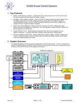
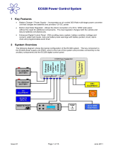
These diagrams show the typical configuration of the EC325 system.
The key component is the EC325 power supply unit (PSU), which is the hub of the system and provides
connectivity to the ancillary components and the EC325 digital control panel.
EC325 Power Control System Overview - Key Features
•325W (~25A) Power Converter - Converts the 240v mains supply into 12v DC power to run the leisure
equipment and supply the battery charger.
•Intelligent ‘offline’ Battery Charger - Uses a process of disconnecting the leisure battery from the leisure
equipment during the charging process, which allows the battery charger to charge batteries quicker,
recover heavily discharged batteries and achieve a higher final charge level than traditional battery chargers.
• Built-in dual Solar Regulator - Allows the direct connection of a 20 to 100W solar panel without the need for
additional components. The dual regulator charges both the vehicle and leisure batteries simultaneously.
• System Monitor Circuit - Monitors key components within the power supply to ensure optimum operation.
A simple ‘traffic light’ indicator shows the power supply status.
• Enhanced Digital Control Panel - With scrolling menu system, battery condition (voltage and current),
water tank levels, tank and battery level warnings with battery protect circuit, alarm clock and programmable
event timer for automatic operation for 12v diesel heater, lighting, alarm system & 240v airconditioner via a relay.
• The key component is the EC325 power supply unit (PSU), which is the hub of the system and provides
connectivity to the ancillary components and the EC325 digital control panel.
Ask us to demonstrate the Sargent EC325 - Power Supply Unit
and see the many innovative features of this revolutionary PSU!
ECU325PSU_4PPBrochure_V3_b9022.indd 1 9/8/11 2:16:14 PM

EC 325 Power Supply Details
For complete operation details refer to our Instruction
& Specifications Manual available from Wirraway
Motorhomes as a PDF document that will be emailed
to you on request. Some of this information is
included in the following text and illustrations, refer to
instruction manual for full operating instructions.
3.1 Battery Charger
The EC325PSU incorporates an intelligent ‘offline’
battery charger that disconnects the leisure equipment
from the battery while it is being charged. This process
allows the charger to use higher charging voltages and
to accurately control the charging current.
No other equipment may be connected directly to the
battery while charging is taking place. This intelligent
battery charger draws power from the power converter
when the mains 230v supply is turned on and from
the vehicle alternator when the engine is running,
therefore the leisure battery is always charged via the
intelligent battery charger. The charger can be preset
at instillation for either Gel or Lead Acid batteries.
The EC325 system also incorporates a battery
compartment temperature sensor, which monitors the
battery ambient temperature to allow the charger to
adjust the charging current if the battery is very cold or
hot to optimise performance.
3.2 Residual Current Device
& Miniature Circuit Breakers
The Residual Current Device (RCD) is basically
provided to protect the user from lethal electric shock.
The RCD will turn off (trip) if the current flowing in the
live conductor does not fully return down the neutral
conductor, i.e. some current is passing through a
person down to earth or through a faulty appliance.
To ensure the RCD is working correctly, the test button
should be operated each time the vehicle is connected
to the mains supply.
The Miniature Circuit Breakers (MCB’s) operate in a
similar way to traditional fuses and are provided to
protect the wiring installation from overload or short
circuit. If an overload occurs the MCB will switch off
the supply. If this occurs you should investigate the
cause of the fault before switching the MCB back on.
3.3 System Monitor
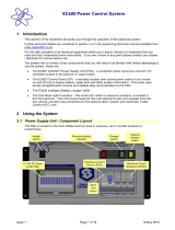
The system monitor circuit
checks the power supply
key components to ensure
optimum operation. The
current status is displayed
on the front of the PSU
by the means of a clear
indication that illuminates in
different colours depending
on the PSU status.
EC325 Power Control System
Issue 01B Page 3 of 16 28 January 2007
1 Template
Instructions
<<Delete before
use>>
3.2 Residual Current Device & Miniature Circuit Breakers
The Residual Current Device (RCD) is basically provided
to protect the user from lethal electric shock. The RCD will
turn off (trip) if the current flowing in the live conductor
does not fully return down the neutral conductor, i.e. some
current is passing through a person down
to earth or
through a faulty appliance.
To ensure the RCD is working correctly, the test button
should be operated each time the vehicle is connected to
the mains supply (see section 5.1)
The Miniature Circuit Breakers (MCB’s) operate in a similar
way to traditional fuses and are provided to protect the
wiring installation from overload or short circuit. If an
overload occurs the MCB will switch off the supply. If this
occurs you s
hould investigate the cause of the fault before
switching the MCB back on.
The following table shows the rating and circuit allocation for the three MCB’s
MCB Rating Wire Colour Description
1 10 Amps White 230v Sockets
2 10 Amps White (Yellow for heater) Extra 230v Sockets / Heater
3 6 Amps Black (Blue for water heater)
Fridge / Water Heater / 12v Charger
(internally connected)
3.3 System Monitor
The system monitor circuit checks the power supply key components to ensure
optimum operation. The current stat
us is displayed on the front of the PSU by
the means of a clear indication that illuminates in different colours depending
on the PSU status.
Left
Centre
Right
Status Indication description
- - G
Good
Mains supply on, PSU status good.
- - -
Good
Mains supply off, PSU status good.
- O G
Warning
Mains supply on, PSU in warning mode. In this mode the PSU will
limit the output current to protect the unit from damage. It is still safe
to use the unit but the fault should be investigated. Typical causes are
battery temperature sensor unplugged, cooling fan not working,
internal sensors disconnected or failed.
- O -
Warning
Mains supply off, PSU in warning mode.
R O G
Failure
Mains supply on, PSU in overheat failure mode. In this mode the PSU
will shutdown and all equipment will be switched off. The cooling fan
will continue to run until the unit cools down. Typical causes are short-
circuited DC output, battery connected in reverse, cooling fan failed,
cooling vents blocked / covered, problem caused by prolonged use in
warning mode.
R - G
Failure
Mains supply on, PSU in overheat failure mode.
R O -
Failure
Mains supply off, PSU in overheat failure mode.
Test
Button
RCD
MCB’s
ECU325PSU_4PPBrochure_V3_b9022.indd 2 9/8/11 2:16:15 PM

3.4 Power Converter
The EC325PSU contains a power converter that powers
the leisure equipment when the 240v mains supply is
connected. This module supplies 13.5v DC to the leisure
equipment up to a maximum of 25 Amps (325 Watts).
The power converter also supplies power to the
intelligent battery charger, therefore the available
power is distributed between the leisure load and the
charger, with the leisure load taking priority as
per the following example:
Leisure load Available power for battery charger
10A 15A
15A 10A
20A 5A
25A 0A
3.5 Solar Panel Converter
The EC325PSU incorporates a built-in dual channel
Solar Regulator that allows the direct connection
of a 20 to 100W solar panel without the need for
additional components. The dual regulator charges
both the vehicle and leisure batteries simultaneously and
connects to the PSU via a dedicated
connector on the base of the unit.
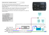
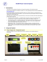
4.1 EC 200 Control Panel
Layout and Buttons
The following diagram shows the
control panel layout and button
functions
4.4 EC 200 Control Panel Event Timer
Example: The event timer is designed to allow the leisure
vehicle user to turn the 12v power on or off
(in the same way as using the control panel power button)
without being in the vehicle.
This allows to turn ON or OFF at a predetermined time
your 12v diesel heater, lighting, alarm system and your
240v airconditioner via a relay.
Example:
To turn on one interior light at 11.00pm for 1 hour
Ensure the clock is set to the correct time Scroll
to the ‘Set Event Timer?’ screen.
Following the instruction in section 4.3,
set the ON time to 23:00 and the OFF time to 24:00
Scroll to the ‘Event Timer=’ screen and select ON
Scroll to the main control panel display and ensure a
hash (#) is displayed in the right of the display
Turn all lights and 12v equipment off in the vehicle except
the light that you want the event timer to automatically
switch on Turn the 12v power off on the control panel
Exit the vehicle.
At 11:00pm (23:00) the control panel will switch the 12v
power on and therefore any equipment that was left
switched on will be turned ON.
The 12v power will be switched OFF at Midnight (24:00).
E C 32 5 P ow er C ontrol S ys te m
Iss ue 01B P age 6 of 16 28 J anua ry 2007
1 Template
Ins truc tion s
<<Delete before
use>>
4 C ontrol P anel Details
4.1 L ay out and B uttons
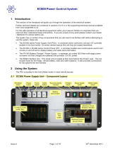
T he following diagram shows the control panel layout and button functions.
Note: to remove the decorative bezel, pull down and lift forward as indicated by the blue arrows.
Item F unction Options / Notes
P ower O N / OF F
Use to turn the main leisure power on and
o.
T he adjacent LE D is illuminated when
the power is O N.
B attery SE LE CT
Use to select the Leisure or V ehicle battery.
Pr ess the button to toggle between the
L e i s u r e and V eh i c l e ba t t e r i e s . W hen a
battery is selected this battery will be used
as the power source and will also be
charged by the charger.
T he adjacent LE D is illuminated when
the VE HICL E battery is selected; by
default when the power is initially turned
on the Le isure battery is selected and is
indicated by the battery
select LE D o.
P ump O N/ OF F
Use to turn the water pump(s) power on and
o (see section 4.3)
T he adjacent LE D is illuminated when
the pump power is O N.
Aux O N / O FF
Use to turn the Auxiliary power on and o
(see manufacturers handbook for detail of
what items are operated by the auxiliary
function).
T he adjacent LE D is illuminated when
the auxiliary power is O N.
Scr oll UP
Use to scroll the display up (settings section
of the menu) or adjust the selected setting
(see s ection 4.3)
Scr oll DOW N
Use to scroll the display down (readings
section of the menu) or adjust the selected
setting (see section 4.2)
Note: the menu screens operate in a
continuous loop, therefore you can use
either the UP or DOW N buttons to
move to any screen
S elect
Use to select a menu item within the
settings section (see section 4.2 & 4.3)
Use to move to the next setting, when
entering alarm / event times
Note: the display backlight operated for approximately 6 seconds after any key press .
P ower
ON / OFF
P ump(s)
ON / OFF
Auxili ary
ON / OFF
Ba ttery
S elec t
Indica tor
L amps x4
S cr oll
Up /
Adju s t
S cro
ll
Down /
Adju s t
S elec t
L CD
Dis play
4.1_Functions_Page_6_Table.pdf 17/7/08 11:43:09 AM
ECU325PSU_4PPBrochure_V3_b9022.indd 3 9/8/11 2:16:15 PM

EC 200 Control Panel & EC325 - PSU
RV Industries Most Innovative Power Supply Unit
is used in the Wirraway 260, The Motorhome of the Year!
Trade Enquiries & Technical Information Contact Our Sales Team
Wirraway Motorhomes, 6B Hynes Court, Mildura Vic 3500
Phone / Fax: (03) 50 230 230 - E: wirraway@ncable.com.au - www.wirraway.com.au
Sargent ECU325PSU_Wirraway Brochure_v3 Copyright© Rex Willmer 2014
The Sargent
EC325 PSU & EC 200 Control Panel
are available exclusively from
Wirraway Motorhomes
Authorised National Distributor
for Sargent Electrical Services Ltd
Wirraway
Motorhomes
is a Member
of the RVMAA
E C 32 5 P ow er C ontrol S ys te m
1 Templa te
Ins truc tion s
<<Delete before
use>>
6 T echnic al Data & A pprova ls
6.1 Outline S pecification
INP UT 240v 240 Volts / 0 to 16 Amps + / - 10%
OUT P UT 240v
RCD protected, 3 x MC B outputs of 10, 10 and 6A via 2 x
9 way connectors
INP UT 12v 2 x 20A battery inputs via a single 6 way connector
S OLAR INP UT
1 x Dedicated s olar panel input (20 to 100W panel) via a 4
way connector
OUT P UT 12v
25A total output via 4 x 16A switched channels protected
by 12 fused outputs via a 15 way connector
Integrated CH AR G E R
Input 220-240 Volts AC +/- 10%, F requency 50 Hz +/- 6%,
C urrent 3A max.
DC O utput 13.5 Volts nominal, C urrent 25 Amps max (325
W atts).
S ignal INP UT
4 x F resh water level, 2 x W as te water level, 1 x E ngine
running, 2 x battery temp sensor via a 10 way connector
F resh water negative s ens ed
W aste water negative s ens ed
Data IN / O UT
Data communication and power to C ontrol P anel via 20
way I DC header connector
IP rating IP 31
Operating
temperature
Ambient 0 to 35° C entigrade
PS U case temperature with full load 65° C Max
Automatic s hutdown and restart
if overheated / overloaded
6.2 Dimens ions
Overall size (HxW xD) 240 x 370 x 110mm F ixing centres 210 x 360mm
E C 325 PS U
C learances 75mm above, 20mm below, 50mm left & right W eight 3.8 K g
Overall size (HxW xD) 80 x 193 x 40mm F ixing centres 175mm
E C 325 C ONTR OL
PA NE L
C ut-out size (HxW ) 60 x 165mm W eight 170 g
6.3 Approva ls
S ys tem: BSE N 164 8-1, BSE N1648-2 compliant, BS 767 1: 2001 compliant
R esidual C urrent Device: RCD 40A 30mA trip to B S E N 610 08
Miniature C ircuit B reakers : MC B ’s (10 & 6A) type C 6000 A breaking capacity to BSE N 60898
E lectro Magnetic C ompatibility (E MC ) directive 89/336/EE C
Integrated C harger: BS E N 6033 5-1/2.29, 89/336/EE C , I E C 61000 -3.2/3:1995 , E MC certificate 06C 0116 6LBS 01
3
rd
party tested.
6.4 Dec laration of C onformity
E quipment: Leisure P ower C ontrol S ystem Model name: E C 325 PS U / E C 325 C P / -S TD / -DLX
I hereby declare that the equipment named above has been designed to comply with the relevant sections of the
above referenced approvals. The unit complies with all ess ential requirements of the Directives.
S igned: Name: P osition: Manufacturer:
Multi Stage
6.1 TechSpecs_Page14.pdf 17/7/08 11:45:43 AM
Ask us to demonstrate the Sargent EC325 - Power Supply Unit
and see the many innovative features of this revolutionary PSU!
ECU325PSU_4PPBrochure_V3_b9022.indd 4 9/8/11 2:16:22 PM
/
