
J Series
2.0, 2.4, and 3.0kW
User Manual
020-100707-01


J Series
2.0, 2.4, and 3.0kW
User Manual
020-100707-01

NOTICES
COPYRIGHT AND TRADEMARKS
© 2011 Christie Digital Systems USA, Inc. - All rights reserved.
All brand names and product names are trademarks, registered trademarks or trade names of their respective holders.
REGULATORY
The product has been tested and found to comply with the limits for a Class A digital device, pursuant to Part 15 of the FCC Rules. These limits
are designed to provide reasonable protection against harmful interference when the product is operated in a commercial environment. The
product generates, uses, and can radiate radio frequency energy and, if not installed and used in accordance with the instruction manual, may
cause harmful interference to radio communications. Operation of the product in a residential area is likely to cause harmful interference in which
case the user will be required to correct the interference at the users own expense.
This Class A digital apparatus complies with Canadian ICES-003.
Cet appareil numérique de la classe A est conforme à la norme NMB-003 du Canada.
㧊 ₆₆⓪ 㠛ⶊ㣿 (A )㦒⪲ 㩚㧦䕢㩗䞿❇⪳㦚 䞲 ₆₆㧊㡺┞ 䕦ⰺ㧦 ⡦⓪ ㌂㣿㧦⓪ 㧊㩦㦚 㭒㦮䞮㔲₆ ⧒Ⳇ , Ṗ㩫 㣎㦮 㰖㡃㠦㍲ ㌂㣿䞮⓪ ộ㦚
⳿㩗㦒⪲ 䞿┞┺ .
GENERAL
Every effort has been made to ensure accuracy, however in some cases changes in the products or availability could occur which may not be
reflected in this document. Christie reserves the right to make changes to specifications at any time without notice. Performance specifications
are typical, but may vary depending on conditions beyond Christie's control such as maintenance of the product in proper working conditions.
Performance specifications are based on information available at the time of printing. Christie makes no warranty of any kind with regard to this
material, including, but not limited to, implied warranties of fitness for a particular purpose. Christie will not be liable for errors contained herein
or for incidental or consequential damages in connection with the performance or use of this material.
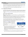
The product is designed and manufactured with high-quality materials and components that can be recycled and reused. This symbol
means that electrical and electronic equipment, at their end-of-life, should be disposed of separately from regular waste. Please dispose of
the product appropriately and according to local regulations. In the European Union, there are separate collection systems for used
electrical and electronic products. Please help us to conserve the environment we live in!
Canadian manufacturing facility is ISO 9001 and 14001 certified.
GENERAL WARRANTY STATEMENTS
For complete information about Christie limited warranty, please contact your Christie dealer. In addition to the other limitations that may be
specified in Christie limited warranty, the warranty does not cover:
a. Damage occurring during shipment, in either direction.
b. Projector lamps (See Christie separate lamp program policy).
c. Damage caused by use of a projector lamp beyond the recommended lamp life, or use of a lamp supplied by a supplier other than Christie.
d. Problems caused by combination of the product with non-Christie equipment, such as distribution systems, cameras, video tape recorders,
etc., or use of the product with any non-Christie interface device.
e. Damage caused by misuse, improper power source, accident, fire, flood, lightening, earthquake or other natural disaster.
f. Damage caused by improper installation/alignment, or by product modification, if by other than a Christie authorized repair service
provider.
g. For LCD projectors, the warranty period specified applies only where the LCD projector is in “normal use.” “Normal use” means the LCD
projector is not used more than 8 hours a day, 5 days a week. For any LCD projector where “normal use” is exceeded, warranty coverage
under this warranty terminates after 6000 hours of operation.
h. Failure due to normal wear and tear.
PREVENTATIVE MAINTENANCE
Preventative maintenance is an important part of the continued and proper operation of your product. Please see the Maintenance section for
specific maintenance items as they relate to your product. Failure to perform maintenance as required, and in accordance with the maintenance
schedule specified by Christie, will void the warranty.

Table of Contents
J Series 2.0, 2.4, and 3.0kW User Manual i
020-100707-01 Rev. 1 (10-2011)
1: Introduction
1.1 Labels and Marking .....................................................................................................................1-1
1.2 Purchase Record and Service Contacts .......................................................................................1-2
1.3 Projector Overview......................................................................................................................1-3
1.3.1 How the Projector Works ....................................................................................................1-3
1.3.2 User Interface Overview......................................................................................................1-3
1.3.3 List of Components..............................................................................................................1-3
1.3.4 Key Features ........................................................................................................................1-4
1.4 Safety Warnings and Guidelines .................................................................................................1-5
1.4.1 General Precautions .............................................................................................................1-5
1.4.2 AC /Power Precautions........................................................................................................1-6
1.4.3 Lamp Precautions ................................................................................................................1-6
2: Installation and Setup
2.1 Projector Quick Setup and Installation........................................................................................2-1
2.2 Detailed Setup and Installation....................................................................................................2-7
2.2.1 About the projector ..............................................................................................................2-7
2.2.2 Installation Considerations ..................................................................................................2-10
2.2.3 Hoisting Procedure ..............................................................................................................2-12
2.2.4 Stacking Procedure ..............................................................................................................2-13
2.2.5 Alignment Procedure ...........................................................................................................2-16
2.3 Types of Installations...................................................................................................................2-18
2.3.1 Projector Position and Mounting .........................................................................................2-21
2.3.2 Mounting..............................................................................................................................2-25
2.3.3 Adjusting Projector Height/Tilt ...........................................................................................2-26
2.3.4 Basic Optical Alignment......................................................................................................2-26
2.3.5 Advanced Optical Alignment ..............................................................................................2-27
2.3.6 Powering Down ...................................................................................................................2-29
2.3.7 Connecting Communications...............................................................................................2-30
2.3.8 Projector Communications ................................................................................................2-35
2.4 Connecting Sources .....................................................................................................................2-36
3: Operation
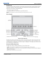
3.1 Operating the Projector................................................................................................................3-1
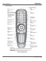
3.1.1 Remote Keypad Commands ................................................................................................3-4
3.2 Navigating the Menus..................................................................................................................3-8
3.3 Using Inputs and Channels ..........................................................................................................3-12
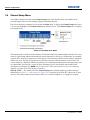
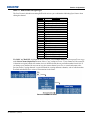
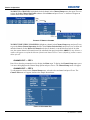
3.4 Channel Setup Menu ...................................................................................................................3-14
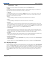
3.5 Adjusting the Image.....................................................................................................................3-17
3.6 Size and Position Menu ...............................................................................................................3-18
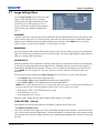
3.7 Image Settings Menu ...................................................................................................................3-23
3.8 Configuration - Adjusting System Parameters and Advanced Controls ....................................3-31
3.9 Lamp Menu..................................................................................................................................3-50
3.10 Input Switching & PIP Menu ....................................................................................................3-52
3.11 Status .........................................................................................................................................3-54

ii J Series 2.0, 2.4, and 3.0kW User Manual
020-100707-01 Rev. 1 (10-2011)
Table of Contents
3.12 Using Multiple Projectors......................................................................................................... 3-54
3.13 Remote Control of the Projector............................................................................................... 3-57
3.14 Alarms ...................................................................................................................................... 3-58
4: Web User Interface
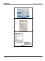
4.1 Logging On ................................................................................................................................. 4-1
4.2 Navigating the Web User Interface............................................................................................. 4-2
4.2.1 Help Text............................................................................................................................. 4-2
4.3 Basic Operation........................................................................................................................... 4-3
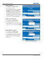
4.3.1 Main Tabbed Page - General .............................................................................................. 4-3
4.3.2 Main Tabbed Page - Status ................................................................................................. 4-3
4.3.3 Main Tabbed Page - Lens ................................................................................................... 4-4
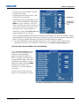
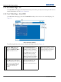
4.3.4 Tools Tabbed Page - Virtual OSD ...................................................................................... 4-4
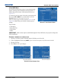
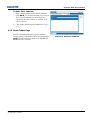
4.3.5 Admin Tabbed Page - System............................................................................................. 4-6
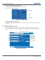
4.3.6 Admin Tabbed Page- Users ................................................................................................ 4-8
4.3.7 Advanced Tabbed Page - RTE............................................................................................ 4-9
4.3.8 About Tabbed Page............................................................................................................. 4-13
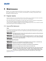
5: Maintenance
5.1 Projector Location....................................................................................................................... 5-1
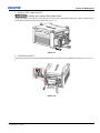
5.1.1 Lamp and Filter Replacement ............................................................................................. 5-1
5.2 Replacing the Projection Lens .................................................................................................... 5-6
5.3 Cleaning the Lens ....................................................................................................................... 5-8
5.4 Liquid Coolant Maintenance....................................................................................................... 5-8
5.4.1 Liquid Cooler (P/N: 003-100668-XX)................................................................................ 5-8
5.5 Power Cord and Attachments ..................................................................................................... 5-10
5.6 Ventilation................................................................................................................................... 5-11
5.7 Replacing Keypad Batteries........................................................................................................ 5-11
5.8 Servicing Requirements.............................................................................................................. 5-11
6: Troubleshooting
6.1 Power .......................................................................................................................................... 6-1
6.1.1 Projector Does Not Power ON............................................................................................ 6-1
6.2 Lamp ........................................................................................................................................... 6-1
6.2.1 Lamp Does Not Ignite......................................................................................................... 6-1
6.2.2 Lamp Suddenly Turns OFF................................................................................................. 6-2
6.2.3 Flicker, Shadows Or Dimness............................................................................................. 6-2
6.3 LCD............................................................................................................................................. 6-2
6.3.1 Blank Screen, No Menu Displaying ................................................................................... 6-2
6.4 Remote Keypad........................................................................................................................... 6-2
6.4.1 Remote Keypad Does Not Seem to Work .......................................................................... 6-2
6.5 OSD............................................................................................................................................. 6-3
6.5.1 The OSD Menu does not display ........................................................................................ 6-3
6.6 Ethernet....................................................................................................................................... 6-3
6.6.1 Trouble Establishing Communication with Projector......................................................... 6-3

Table of Contents
J Series 2.0, 2.4, and 3.0kW User Manual iii
020-100707-01 Rev. 1 (10-2011)
6.7 Displays .......................................................................................................................................6-3
6.7.1 The projector is on but there is no display...........................................................................6-3
6.7.2 Severe Motion Artifacts.......................................................................................................6-3
6.7.3 Image Appears ‘Squeezed’ or Vertically Stretched into Center of Screen..........................6-4
6.7.4 The Display is Jittery or Unstable........................................................................................6-4
6.7.5 The Display is Faint.............................................................................................................6-4
6.7.6 The Upper Portion of the Display is Waving, Tearing or Jittering......................................6-4
6.7.7 Portions of the Display are Cut Off or Warped to the Opposite edge .................................6-4
6.7.8 Display Appears Compressed (Vertically Stretched) ..........................................................6-4
6.7.9 Data is Cropped from Edges................................................................................................6-4
6.7.10 Display Quality Appears to Drift from Good to Bad, Bad to Good .................................6-4
6.7.11 Display has Suddenly Frozen ............................................................................................6-5
6.7.12 Colors in the Display are Inaccurate..................................................................................6-5
6.7.13 Display is Not Rectangular ................................................................................................6-5
6.7.14 Display is “Noisy” .............................................................................................................6-5
6.8 Web Interface ..............................................................................................................................6-6
6.8.1 After upgrading the projector software, the Web pages do not display correctly ...............6-6
6.8.2 A backup or Interrogator file cannot be saved.....................................................................6-6
7: Specifications
7.1 Image Performance......................................................................................................................7-1
7.1.1 Pixel Format ........................................................................................................................7-1
7.1.2 Nominal Brightness (ANSI Lumens) .................................................................................7-1
7.1.3 Contrast................................................................................................................................7-1
7.1.4 Luminance Uniformity ........................................................................................................7-1
7.1.5 Color Uniformity .................................................................................................................7-1
7.1.6 Gamma.................................................................................................................................7-2
7.1.7 Grayscale/Color Resolution.................................................................................................7-2
7.1.8 Color Temperature...............................................................................................................7-2
7.1.9 Convergence ........................................................................................................................7-2
7.1.10 Blemishes...........................................................................................................................7-3
7.1.11 Pixel Defects ......................................................................................................................7-3
7.2 Feature Set ...................................................................................................................................7-3
7.2.1 Airflow ................................................................................................................................7-3
7.2.2 Air Filters (Optional) ...........................................................................................................7-3
7.2.3 Dust Sealing.........................................................................................................................7-3
7.2.4 ILS (Intelligent Lens System)..............................................................................................7-3
7.2.5 Projection Lens Compatibility .............................................................................................7-4
7.2.6 Automatic Fans ....................................................................................................................7-4
7.2.7 Constant Lamp Output Management...................................................................................7-4
7.2.8 Shutter .................................................................................................................................7-5
7.2.9 Lamps...................................................................................................................................7-5
7.2.10 Status LED.........................................................................................................................7-5
7.2.11 Electronics/SW .................................................................................................................7-5
7.3 Image Processor Performance .....................................................................................................7-6
7.4 Input (Source Signal) Compatibility ...........................................................................................7-6

iv J Series 2.0, 2.4, and 3.0kW User Manual
020-100707-01 Rev. 1 (10-2011)
Table of Contents
7.4.1 Analog (Only) Input............................................................................................................ 7-6
7.4.2 Twin HDMI Input ............................................................................................................... 7-6
7.4.3 Dual Link DVI Input........................................................................................................... 7-7
7.4.4 Video Decoder Input........................................................................................................... 7-7
7.4.5 Dual 3G/HD/SD - SDI Input............................................................................................... 7-7
7.5 Control Signal Compatibility ..................................................................................................... 7-7
7.5.1 Projector Control................................................................................................................. 7-7
7.5.2 Control Receiver ................................................................................................................. 7-7
7.5.3 RS-232 ................................................................................................................................ 7-8
7.5.4 RS-422 ................................................................................................................................ 7-8
7.5.5 Ethernet ............................................................................................................................... 7-8
7.5.6 USB 2.0 Device Port .......................................................................................................... 7-8
7.5.7 GPIO ................................................................................................................................... 7-8
7.5.8 DMX512 Interface .............................................................................................................. 7-8
7.5.9 Built-In Keypad and Display .............................................................................................. 7-8
7.5.10 Convenience Light ............................................................................................................ 7-8
7.5.11 MMC Slot ......................................................................................................................... 7-8
7.6 Power Requirements ................................................................................................................... 7-9
7.6.1 Lamp Specification ............................................................................................................. 7-9
7.7 Physical Specifications ............................................................................................................... 7-9
7.7.1 Size...................................................................................................................................... 7-9
7.7.2 Adjustment .......................................................................................................................... 7-10
7.7.3 Weight................................................................................................................................. 7-10
7.8 Reliability and Serviceability...................................................................................................... 7-10
7.8.1 Reliability............................................................................................................................ 7-10
7.8.2 Serviceability ...................................................................................................................... 7-10
7.9 Environment................................................................................................................................ 7-10
7.9.1 Temperature/Humidity/Altitude.......................................................................................... 7-10
7.10 Accessories and Service Components ...................................................................................... 7-11
7.11 Regulatory................................................................................................................................. 7-11
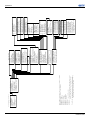
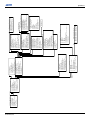
A: Menu Tree
A.1 J Series Menu Tree..................................................................................................................... A-1
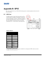
B: GPIO
B.1 GPIO Port................................................................................................................................... B-1
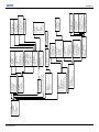
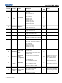
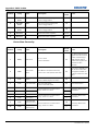
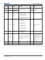
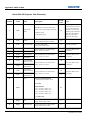
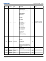
C: DMX / ArtNet
C.1 DMX and Real Time Events ...................................................................................................... C-1
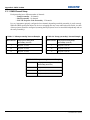
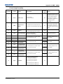
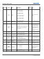
C.1.1 DMX Channel Setup .......................................................................................................... C-2

J Series 2.0, 2.4, and 3.0kW User Manual 1-1
020-100707-01 Rev. 1 (10-2011)
1 Introduction
Every effort has been made to ensure the information in this document is accurate and reliable; however,
due to constant research the information in this document is subject to change without notice.
USERS/OPERATORS: This manual is intended for trained users operating professional high-brightness
projection systems. Such users may also be trained to replace the lamp and air filter, but cannot install the
projector or perform any service functions on the J Series projector.
SERVICE: Only Christie accredited technicians knowledgeable about all potential hazards associated
with high voltage, ultraviolet exposure and high temperatures generated by the lamp and associated
circuits are authorized to 1) assemble/install the projector and 2) perform service functions inside the
projector.
This manual contains the following sections:
• Section 1 Introduction
• Section 2 Installation and Setup
• Section 3 Operation
• Section 4 Web User Interface
• Section 5 Maintenance
• Section 6 Troubleshooting
• Section 7 Specifications
• Appendix A: Menu Tree
• Appendix B: GPIO
• Appendix C: DMX / ArtNet
1.1 Labels and Marking
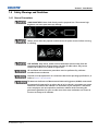
Observe and follow any warnings and instructions marked on the projector.
Indicates a hazardous situation which, if not avoided, will result in death or serious
injury. This signal word is to be limited to the most extreme situations.
Indicates a hazardous situation which, if not avoided, could result in death or serious
injury.
Indicates a hazardous situation which, if not avoided, could result in minor or moderate
injury. It may also be used without the safety alert symbol as an alternative to
“NOTICE”.

1-2 J Series 2.0, 2.4, and 3.0kW User Manual
020-100707-01 Rev. 1 (10-2011)
Section 1: Introduction
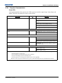
1.2 Purchase Record and Service Contacts
Whether the projector is under warranty or the warranty has expired, Christies highly trained and extensive
factory and dealer service network is always available to quickly diagnose and correct projector malfunctions.
Complete service manuals and updates are available for all projectors. Should a problem be encountered with
any part of the projector, contact your dealer. In most cases, servicing is performed on site. If you have
purchased the projector, fill out the information below and keep with your records.
* The serial number can be found on the license label located on the back of the projector.
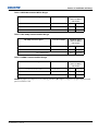
Table 1.1
Dealer:
Dealer or Christie Sales/Service Contact Phone Number:
Projector Serial Number*:
Purchase Date:
Installation Date:
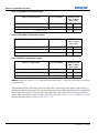
Table 1.2 Ethernet Settings
Default Gateway:
DNS Server:
Projector DLP Address:
Projector Mgmt IP Address:
Subnet Mask:

Section 1: Introduction
J Series 2.0, 2.4, and 3.0kW User Manual 1-3
020-100707-01 Rev. 1 (10-2011)
1.3 Projector Overview
The J Series is a family of high resolution video/graphics 3 chip 1080p HD, SXGA+ and WUXGA projectors,
see Table 1.3 J Series Projectors. These projectors are based on DLP® technology provided by Texas
Instruments.
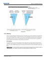
1.3.1 How the Projector Works
The projector accepts data/graphics and video input signals for projection onto front or rear screens. Light is
generated by a xenon lamp, then modulated by three Digital Micro-mirror Device (DMD) panels that provide
digitized red, green or blue color information. Light from the “ON” pixels of each panel is reflected, converged
and then projected to the screen through a single front lens, where all pixels are perfectly superimposed as a
sharp full-color image.
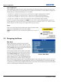
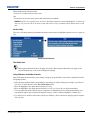
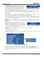
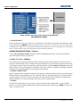
1.3.2 User Interface Overview
The projector can be controlled via a menu system displayed on the image. The menu system can be controlled
by an IR remote, wired remote or through the built-in keypad. The LCD screen and built-in keypad allow
functions to be controlled without the need of an OSD display, and provide a quickly accessible interface to
view error reporting. The functions on the OSD can also be controlled using the Christie Serial Protocol, via a
serial or Ethernet connection to the projector. The Web interface provides access to the menu system as a
Virtual OSD (On-screen display) and to features that maintain the projector software and settings.
1.3.3 List of Components
Ensure the following components were received with the projector:
Projector with Built-In Keypad (LCD status display)
IR remote keypad (includes two, 1.5V AA batteries and an XLR to mini-stereo cable conversion to wired)
Line cord
Lens Mount Security Screw (M6x10mm long, Qty. 2)
Lens Mount Security Screw Driver (5mm Hex, Qty. 1)
Warranty Card
Web Registration Form

1-4 J Series 2.0, 2.4, and 3.0kW User Manual
020-100707-01 Rev. 1 (10-2011)
Section 1: Introduction
1.3.4 Key Features
• Up to 22,000 lumens
• HD (1080p), SXGA+ or WUXGA resolution
• Xenon lamp with 1900W, 2400W or 3000W options
• 10-bit image processor electronics with modular design
• Active fan control for minimum noise level
• User interchangeable projection lenses with no-tool mounting
• LiteLOC for constant brightness maintenance
• Intelligent Lens System (ILS)
• Motorized lens mount for all models
• Auto-setup feature
• Integrated ChristieNET
• Networking ability through RS-232 and RS-422 connectors
• Status LED display on built-in keypad for easy projector status monitoring
• Control with remote keypad, wired remote, or built-in keypad
• Four input slots for Optional Input Modules
Refer to Section 7 Specifications for a complete list of technical specifications.
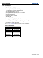
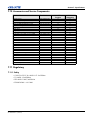
Table 1.3 J Series Projectors
Model Name Part Number
Roadster S+14K-J 132-010113-XX
Roadster HD14K-J 132-011114-XX
Roadster S+18K-J 132-013116-XX
Roadster HD16K-J 132-014117-XX
Roadster S+22K-J 132-016119-XX
Roadster HD20K-J 132-017110-XX
Roadster WU20K-J 132-018111-XX

Section 1: Introduction
J Series 2.0, 2.4, and 3.0kW User Manual 1-5
020-100707-01 Rev. 1 (10-2011)
1.4 Safety Warnings and Guidelines
1.4.1 General Precautions
HIGH BRIGHTNESS. Never look directly into the projector lens. The extreme high
brightness can cause permanent eye damage.
Always power down the projector and disconnect all power sources before servicing
or cleaning.
FIRE HAZARD. Keep hands, clothes and all combustible material away from the
concentrated light beam of the projector. Position all cables where they cannot
contact hot surfaces or be pulled or tripped over.
All installation and maintenance procedures must be performed by a Christie
accredited service technician.
Projector must be operated in an environment that meets operating specifications, as
listed in Section 7 Specifications.
The American Conference of Governmental Industrial Hygienists (ACGIH) recommends
occupational UV exposure for an 8-hour day to be less than 0.1 microwatts per square
centimeters of effective UV radiation. An evaluation of your workplace is advised to
assure employees are not exposed to cumulative radiation levels exceeding the
government guidelines for your area. Be aware that some medications are known to
increase sensitivity to UV radiation.

1-6 J Series 2.0, 2.4, and 3.0kW User Manual
020-100707-01 Rev. 1 (10-2011)
Section 1: Introduction
1.4.2 AC /Power Precautions
Use only the AC power cord supplied. Do not attempt operation if the AC supply and
cord are not within the specified voltage and power range. Refer to the license label
on the back of the projector or Section 7 Specifications for rated voltage and power.
The projector is equipped with a 3-wire plug with a grounding pin. This is a safety
feature. If you are unable to insert the plug into the outlet, contact an electrician to
have the outlet replaced. NEVER defeat the safety purpose of the grounding-type
plug.
Do not allow anything to rest on the power cord. Locate the power cord where
persons walking on it or objects rolling over it cannot damage the cord.
1.4.3 Lamp Precautions
Never attempt to access the lamp while the lamp is ON. After turning the lamp OFF, it
is crucial that you wait at least 5 minutes before handling the lamp. This provides
sufficient time for the lamp cooling fans to properly cool the lamp. For all other
precautions critical for safe removal and replacement of the lamp, refer to 5.1.1 Lamp
and Filter Replacement.

J Series 2.0, 2.4, and 3.0kW User Manual 2-1
020-100707-01 Rev. 1 (10-2011)
2 Installation and Setup
This section explains how to install, connect and optimize the projector for delivery of superior image
quality. Illustrations are graphical representations only and are provided to enhance the understanding of
the written material.
2.1 Projector Quick Setup and Installation
The following instructions are for those preferring a quick setup. Refer to the remaining subsections for
detailed setup instructions.
Always power down the projector and disconnect all power sources before servicing or
cleaning.
Refer to Safety Warnings and Guidelines in Section 5 Maintenance.
STEP 1 - Installing a Projection Lens
The projection lens, shipped separately from the projector, must be installed prior to setting up the projector.
Remove the lens plug from the lens opening in the projector before installing the lens.
Retain the lens plug for projector transportation to protect the optical components
from dust and debris.
IMPORTANT! The lens seals the projector, preventing contaminants from entering the interior of the
projector. Never operate a projector without a lens.
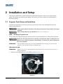
LENS INSTALLATION
IMPORTANT! Remove the rear lens cap from the lens. Keep the front lens cap on the lens to protect it
during installation.
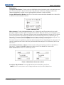
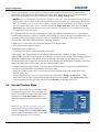
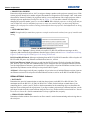
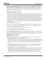
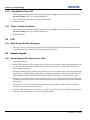
1. Rotate the lens clamp clockwise to the OPEN position, see Figure 2-1.
FIGURE 2-1

2-2 J Series 2.0, 2.4, and 3.0kW User Manual
020-100707-01 Rev. 1 (10-2011)
Section 2: Installation and Setup
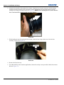
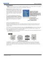
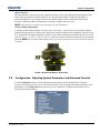
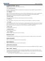
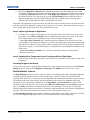
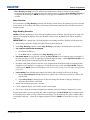
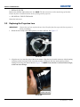
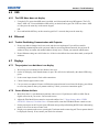
2. Align the lens interface plate with the lens mount. Align the lens electrical connector with the mating
connector on the lens mount. Fully insert the assembly straight into the lens mount opening without
turning. Press using your hand as shown in Figure 2-2. NOTE: When installing the lens, ensure that the
lens is not inserted at an angle, as this can cause damage.
FIGURE 2-2
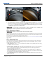
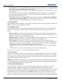
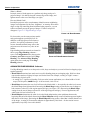
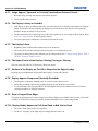
3. While holding the lens flat against the lens mount, rotate the lens clamp clockwise to lock the lens
assembly in place. See Figure 2-3.
FIGURE 2-3
4. Remove the front lens cap.
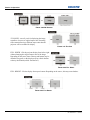
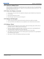
5. For added stability such as motion applications, fasten the security screws provided with the lens mount.
Refer to Figure 2-4.

Section 2: Installation and Setup
J Series 2.0, 2.4, and 3.0kW User Manual 2-3
020-100707-01 Rev. 1 (10-2011)
FIGURE 2-4
6. Use a 5mm hex driver to fasten the red security screws provided with the lens mount (Figure 2-4), or hand
tighten the lens retaining screws attached to the lens. NOTES: 1) Recommended for heaviest lenses such
as 0.73:1 and 1.2:1. 2) The red security screws MUST be installed when hoisting the projector overhead,
or installing the projector in an overhead position.
Use of the lens red security screws or the lens retaining screws is required if the
projector is hoisted or installed in an overhead position.
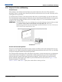
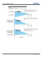
STEP 2 - Positioning the Projector
2 people are required to safely lift and install the projector.
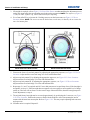
Place the projector on a sturdy, level surface and position it so that it is perpendicular to the screen at a suitable
distance. With the projector positioned perpendicular to the screen, the image will appear rectangular instead
of keystoned. To level the projector, adjust the height of the feet.
For more detailed instructions on positioning the projector refer to 2.3.1 Projector Position and Mounting later
in this section.
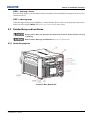
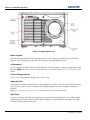
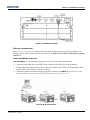
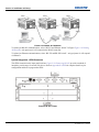
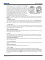
STEP 3 - Connecting a Source
Located at the back of the projector is the input panel where all source connections are made. Each input is
clearly labeled for easy identification. Depending on the type of option card installed, connect your source
using the appropriate cable(s), as follows:
•Analog Input Card, connect 3-, 4-, or 5-wire RGB source to Red/Pr, Green/Y, Blue/Pb, H/C and V using 3,
4 or 5 BNC connectors as required.
•Dual 3G/SD/HD - SDI Input Card, connect SDI (Serial Digital Interface) cable to one of the two inputs, 1-
IN or 2-IN. Both standard-definition (SD) and high-definition (HD) 3GHz signals are accepted and
automatically recognized on either input.
•Dual Link DVI Input Card, connect a single or dual link DVI video signal to the DVI-I connector, an
analog video signal to the DVI-I connector or an analog video signal to the VGA connector. The DVI signal
may contain HDCP (High-Bandwidth Digital Content Protection).
•Twin HDMI Input Card, connect HDMI (High-Definition Multimedia Interface) cable to one of the two
inputs, 1-IN or 2-IN.

2-4 J Series 2.0, 2.4, and 3.0kW User Manual
020-100707-01 Rev. 1 (10-2011)
Section 2: Installation and Setup
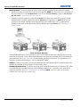
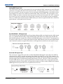
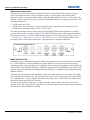
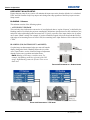
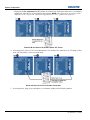
•Video Decoder Input Card, depending on the source you can apply the following;
• Composite video source to 1-CVBS, using a BNC Cable NOTE: Same signal can be used on 4, 5 or 6 when
input is selected as CVBS.
• Component input grouping is selected in the projector menu, see Section 3.8 Configuration - Adjusting
System Parameters and Advanced Controls.
• A component signal on Inputs 4(Pr), 5(Y), 6(Pb) using BNC Connectors. NOTE: Grouped as a component
input, YPbPr.
• S-Video to one of the two, 2-SVID or 3-SVID using S-Video cable.
• S-Video using two BNC cables, with Luma (Y) connected to 4 (Sy) and Chroma (C) connected to 6 (Sc).
NOTE: Must be grouped as 1 S-Video + 1 CVBS.
•DMX512 Interface Card, has two 5pin XLR connectors - 1 (input) male and 1 (output) female. If there is
active communications on the DMX512 Interface card the power LED will blink between low intensity and
high intensity.
Refer to Section 2.4 Connecting Sources for more details.
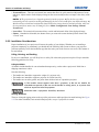
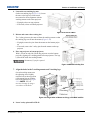
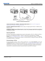
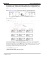
STEP 4 - Connecting the Line Cord
IMPORTANT! Use the line cord provided with the projector. NOTE: Voltage and current requirements are
listed on the license label, located at the back of the projector.
To prevent the line cord from inadvertent disconnection, perform one of the following steps:
For 1900W and 2400W Models
1. Connect the line cord of the projector to the AC receptacle at the AC inlet of the projector, then push the
wire clip over the plug to retain it, as shown in Figure 2-5.
FIGURE 2-5

Section 2: Installation and Setup
J Series 2.0, 2.4, and 3.0kW User Manual 2-5
020-100707-01 Rev. 1 (10-2011)
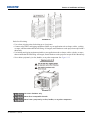
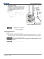
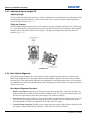
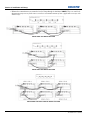
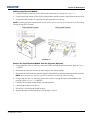
For 3000W Model
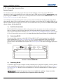
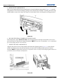
1. Remove the locking pin from the bracket surrounding the AC receptacle at the AC inlet of the projector by
pressing down on the button on the end of the locking pin, and then pull upwards on the pin to remove it,
as shown in Figure 2-6.
FIGURE 2-6
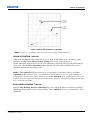
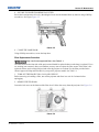
2. Open the cap on the AC plug and line up the slot on the plug with the pin on the receptacle. See Figure 2-7.
FIGURE 2-7

2-6 J Series 2.0, 2.4, and 3.0kW User Manual
020-100707-01 Rev. 1 (10-2011)
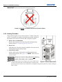
Section 2: Installation and Setup
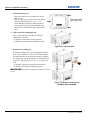
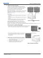
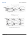
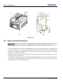
3. Insert the plug fully on to the receptacle. When fully inserted, the cap on the AC plug will rest against the
side of the projector (Figure 2-8).
4. Reinsert the locking pin into the bracket surrounding the AC receptacle by pressing down on the button on
the end of the locking pin and insert the pin into the bracket, as shown in Figure 2-8.
Do not attempt operation if the AC supply and cord is not within the specified ratings.
On power down, wait 5 minutes for the fans to turn OFF before unplugging the
projector. Always switch off the projector before unplugging the AC line cord.
FIGURE 2-8
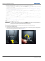
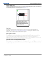
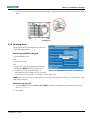
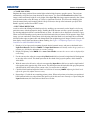
STEP 5 - Power up
After the AC Power has been switched on, the LCD display above the keypad indicates “Please wait” and the 4
LED status indicators at the rear of the projector will be solid amber.
The projector has reached standby and is ready for use when:
• The LCD displays “Standby mode”
• The Status LED is solid amber
• The Lamp LED is off
To turn on the projector, do one of the following:
• Press and hold the power button on either the built-in keypad or the remote control
• Press the power button twice (quickly) on either the built-in keypad or the remote control
Thereafter; the lamp and fans will power on and a green LED will start scrolling back and forth indicating that
the projector is in warm up mode.
The projector is on and ready to display video when the lamp LED and the status LED are both solid green.
NOTE: See Section 3 Operation for a full description of the status indicators.
NOTE: If the projector has a stepper motor lens mount installed and the inserted lens has never been
calibrated, there will be a short period where the projector calibrates all of the lens motors (zoom, focus,
horizontal, and vertical) by moving them through their full range of motion.
Page is loading ...
Page is loading ...
Page is loading ...
Page is loading ...
Page is loading ...
Page is loading ...
Page is loading ...
Page is loading ...
Page is loading ...
Page is loading ...
Page is loading ...
Page is loading ...
Page is loading ...
Page is loading ...
Page is loading ...
Page is loading ...
Page is loading ...
Page is loading ...
Page is loading ...
Page is loading ...
Page is loading ...
Page is loading ...
Page is loading ...
Page is loading ...
Page is loading ...
Page is loading ...
Page is loading ...
Page is loading ...
Page is loading ...
Page is loading ...
Page is loading ...
Page is loading ...
Page is loading ...
Page is loading ...
Page is loading ...
Page is loading ...
Page is loading ...
Page is loading ...
Page is loading ...
Page is loading ...
Page is loading ...
Page is loading ...
Page is loading ...
Page is loading ...
Page is loading ...
Page is loading ...
Page is loading ...
Page is loading ...
Page is loading ...
Page is loading ...
Page is loading ...
Page is loading ...
Page is loading ...
Page is loading ...
Page is loading ...
Page is loading ...
Page is loading ...
Page is loading ...
Page is loading ...
Page is loading ...
Page is loading ...
Page is loading ...
Page is loading ...
Page is loading ...
Page is loading ...
Page is loading ...
Page is loading ...
Page is loading ...
Page is loading ...
Page is loading ...
Page is loading ...
Page is loading ...
Page is loading ...
Page is loading ...
Page is loading ...
Page is loading ...
Page is loading ...
Page is loading ...
Page is loading ...
Page is loading ...
Page is loading ...
Page is loading ...
Page is loading ...
Page is loading ...
Page is loading ...
Page is loading ...
Page is loading ...
Page is loading ...
Page is loading ...
Page is loading ...
Page is loading ...
Page is loading ...
Page is loading ...
Page is loading ...
Page is loading ...
Page is loading ...
Page is loading ...
Page is loading ...
Page is loading ...
Page is loading ...
Page is loading ...
Page is loading ...
Page is loading ...
Page is loading ...
Page is loading ...
Page is loading ...
Page is loading ...
Page is loading ...
Page is loading ...
Page is loading ...
Page is loading ...
Page is loading ...
Page is loading ...
Page is loading ...
Page is loading ...
Page is loading ...
Page is loading ...
Page is loading ...
Page is loading ...
Page is loading ...
Page is loading ...
Page is loading ...
Page is loading ...
Page is loading ...
Page is loading ...
Page is loading ...
Page is loading ...
Page is loading ...
Page is loading ...
Page is loading ...
Page is loading ...
Page is loading ...
Page is loading ...
Page is loading ...
Page is loading ...
Page is loading ...
Page is loading ...
Page is loading ...
Page is loading ...
Page is loading ...
Page is loading ...
Page is loading ...
Page is loading ...
Page is loading ...
Page is loading ...
Page is loading ...
Page is loading ...
Page is loading ...
Page is loading ...
Page is loading ...
Page is loading ...
Page is loading ...
Page is loading ...
Page is loading ...
Page is loading ...
Page is loading ...
Page is loading ...
Page is loading ...
Page is loading ...
Page is loading ...
Page is loading ...
Page is loading ...
-
 1
1
-
 2
2
-
 3
3
-
 4
4
-
 5
5
-
 6
6
-
 7
7
-
 8
8
-
 9
9
-
 10
10
-
 11
11
-
 12
12
-
 13
13
-
 14
14
-
 15
15
-
 16
16
-
 17
17
-
 18
18
-
 19
19
-
 20
20
-
 21
21
-
 22
22
-
 23
23
-
 24
24
-
 25
25
-
 26
26
-
 27
27
-
 28
28
-
 29
29
-
 30
30
-
 31
31
-
 32
32
-
 33
33
-
 34
34
-
 35
35
-
 36
36
-
 37
37
-
 38
38
-
 39
39
-
 40
40
-
 41
41
-
 42
42
-
 43
43
-
 44
44
-
 45
45
-
 46
46
-
 47
47
-
 48
48
-
 49
49
-
 50
50
-
 51
51
-
 52
52
-
 53
53
-
 54
54
-
 55
55
-
 56
56
-
 57
57
-
 58
58
-
 59
59
-
 60
60
-
 61
61
-
 62
62
-
 63
63
-
 64
64
-
 65
65
-
 66
66
-
 67
67
-
 68
68
-
 69
69
-
 70
70
-
 71
71
-
 72
72
-
 73
73
-
 74
74
-
 75
75
-
 76
76
-
 77
77
-
 78
78
-
 79
79
-
 80
80
-
 81
81
-
 82
82
-
 83
83
-
 84
84
-
 85
85
-
 86
86
-
 87
87
-
 88
88
-
 89
89
-
 90
90
-
 91
91
-
 92
92
-
 93
93
-
 94
94
-
 95
95
-
 96
96
-
 97
97
-
 98
98
-
 99
99
-
 100
100
-
 101
101
-
 102
102
-
 103
103
-
 104
104
-
 105
105
-
 106
106
-
 107
107
-
 108
108
-
 109
109
-
 110
110
-
 111
111
-
 112
112
-
 113
113
-
 114
114
-
 115
115
-
 116
116
-
 117
117
-
 118
118
-
 119
119
-
 120
120
-
 121
121
-
 122
122
-
 123
123
-
 124
124
-
 125
125
-
 126
126
-
 127
127
-
 128
128
-
 129
129
-
 130
130
-
 131
131
-
 132
132
-
 133
133
-
 134
134
-
 135
135
-
 136
136
-
 137
137
-
 138
138
-
 139
139
-
 140
140
-
 141
141
-
 142
142
-
 143
143
-
 144
144
-
 145
145
-
 146
146
-
 147
147
-
 148
148
-
 149
149
-
 150
150
-
 151
151
-
 152
152
-
 153
153
-
 154
154
-
 155
155
-
 156
156
-
 157
157
-
 158
158
-
 159
159
-
 160
160
-
 161
161
-
 162
162
-
 163
163
-
 164
164
-
 165
165
-
 166
166
-
 167
167
-
 168
168
-
 169
169
-
 170
170
-
 171
171
-
 172
172
-
 173
173
-
 174
174
-
 175
175
-
 176
176
-
 177
177
-
 178
178
-
 179
179
-
 180
180
-
 181
181
-
 182
182


Christie Christie Roadster HD14K-J User manual
- Category
- Data projectors
- Type
- User manual
Ask a question and I''ll find the answer in the document
Finding information in a document is now easier with AI
Related papers
-
Christie J series 2.4kW User manual
-
Christie Roadster S+ User manual
-
Christie Roadster HD10K-M Installation guide
-
Christie HD14K-M Installation guide
-
-
-
-
-
-
Christie Roadster S+10K-M User manual
Other documents
-
Digital Projection Digital Projection dVision sx+ User manual
-
-
 Vnstw G-700 Operating instructions
-
Dahua LS550UCM-BF User manual
-
Sunco Lighting 99355 User manual
-
 Whitmor 69055916 Operating instructions
-
-
-
Christie Digital Systems Roadster Series User manual
-

