Christie HD14K-M Installation guide
- Category
- Data projectors
- Type
- Installation guide


M Series
Setup Guide
020-100011-07

NOTICES
COPYRIGHT AND TRADEMARKS
Copyright © 2014 Christie Digital Systems USA, Inc. All rights reserved.
All brand names and product names are trademarks, registered trademarks or trade names of their respective holders.
REGULATORY
The product has been tested and found to comply with the limits for a Class A digital device, pursuant to Part 15 of the FCC Rules. These limits
are designed to provide reasonable protection against harmful interference when the product is operated in a commercial environment. The
product generates, uses, and can radiate radio frequency energy and, if not installed and used in accordance with the instruction manual, may
cause harmful interference to radio communications. Operation of the product in a residential area is likely to cause harmful interference in which
case the user will be required to correct the interference at the expense of the user.
This Class A digital apparatus complies with Canadian ICES-003.
Cet appareil numérique de la classe A est conforme à la norme NMB-003 du Canada.
이 기기는 업무용 (A 급)으로 전자파적합등록을 한 기기이오니 판매자 또는 사용자는 이점을 주의하시기 바라며 , 가정 외의 지역에서 사용하는 것을
목적으로 합니다 .
GENERAL
Every effort has been made to ensure accuracy, however in some cases changes in the products or availability could occur which may not be
reflected in this document. Christie reserves the right to make changes to specifications at any time without notice. Performance specifications
are typical, but may vary depending on conditions beyond the control of Christie such as maintenance of the product in proper working
conditions. Performance specifications are based on information available at the time of printing. Christie makes no warranty of any kind with
regard to this material, including, but not limited to, implied warranties of fitness for a particular purpose. Christie will not be liable for errors
contained herein or for incidental or consequential damages in connection with the performance or use of this material.
The product is designed and manufactured with high-quality materials and components that can be recycled and reused. This symbol
means that electrical and electronic equipment, at their end-of-life, should be disposed of separately from regular waste. Please dispose of
the product appropriately and according to local regulations. In the European Union, there are separate collection systems for used
electrical and electronic products. Please help us to conserve the environment we live in!
Canadian manufacturing facility is ISO 9001 and 14001 certified.
GENERAL WARRANTY STATEMENTS
For complete information about the Christie limited warranty, please contact your Christie dealer. In addition to the other limitations that may be
specified in the Christie limited warranty, the warranty does not cover:
a. Damage occurring during shipment, in either direction.
b. Projector lamps (See the separate Christie lamp program policy).
c. Damage caused by use of a projector lamp beyond the recommended lamp life, or use of a lamp supplied by a supplier other than Christie.
d. Problems caused by combination of the product with non-Christie equipment, such as distribution systems, cameras, video tape recorders,
etc., or use of the product with any non-Christie interface device.
e. Damage caused by misuse, improper power source, accident, fire, flood, lightning, earthquake or other natural disaster.
f. Damage caused by improper installation/alignment, or by product modification, if by other than a Christie authorized repair service
provider.
g. For LCD projectors, the warranty period specified applies only where the LCD projector is in “normal use.” “Normal use” means the LCD
projector is not used more than 8 hours a day, 5 days a week. For any LCD projector where “normal use” is exceeded, warranty coverage
under this warranty terminates after 6000 hours of operation.
h. Failure due to normal wear and tear.
PREVENTATIVE MAINTENANCE
Preventative maintenance is an important part of the continued and proper operation of your product. Please see the Maintenance section for
specific maintenance items as they relate to your product. Failure to perform maintenance as required, and in accordance with the maintenance
schedule specified by Christie, will void the warranty.

Table of Contents
M Series Setup Guide i
020-100011-07 Rev. 1 (01-2014)
1: Introduction
1.1 Purchase Record and Service Contacts .......................................................................................1-1
1.1.1 List of Components..............................................................................................................1-1
1.1.2 Key Features ........................................................................................................................1-2
1.2 Safety Warnings and Guidelines .................................................................................................1-3
1.2.1 General Precautions .............................................................................................................1-3
1.2.2 AC /Power Precautions........................................................................................................1-3
1.2.3 Lamp Precautions ................................................................................................................1-4
2: Installation and Setup
2.1 Projector Quick Setup and Installation........................................................................................2-1
2.1.1 Install a Projection Lens ......................................................................................................2-1
2.1.2 Position the Projector...........................................................................................................2-3
2.1.3 Connect a Source .................................................................................................................2-3
2.1.4 Connect the Line Cord.........................................................................................................2-3
2.1.5 Power up ..............................................................................................................................2-4
2.1.6 Select a Source.....................................................................................................................2-4
2.1.7 Adjust the Image..................................................................................................................2-4
2.2 Detailed Setup and Installation....................................................................................................2-4
2.2.1 Mounting..............................................................................................................................2-4
2.2.2 Stacking ...............................................................................................................................2-5
2.2.3 Basic Optical Alignment......................................................................................................2-7
2.2.4 Advanced Optical Alignment ..............................................................................................2-8
2.2.5 Powering Down ...................................................................................................................2-9
2.2.6 Projector Communications ..................................................................................................2-10
3: Operation
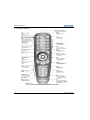
3.1 How to Use the Remote Keypad or Built-In Keypad..................................................................3-1
3.1.1 Guide to Keypads.................................................................................................................3-1
3.1.2 Remote Keypad....................................................................................................................3-2
3.1.3 Wired Remote ......................................................................................................................3-4
3.1.4 Built-in Keypad....................................................................................................................3-4
3.1.5 Overview of LED and Key States........................................................................................3-4
3.1.6 Remote Keypad Commands ................................................................................................3-5
3.2 Navigating the Menus..................................................................................................................3-9
3.3 Alarm Conditions ........................................................................................................................3-12
3.4 SNMP and Email Notifications ...................................................................................................3-13
3.4.1 Controls................................................................................................................................3-13
3.4.2 Items.....................................................................................................................................3-13
3.4.3 Traps ....................................................................................................................................3-14
3.4.4 Email Notification................................................................................................................3-15
4: Maintenance
4.1 Filters ...........................................................................................................................................4-1

ii M Series Setup Guide
020-100011-07 Rev. 1 (01-2014)
Table of Contents
5: Troubleshooting
5.1 Power ...........................................................................................................................................5-1
5.1.1 Projector Does Not Power ON.............................................................................................5-1
5.2 Lamp ............................................................................................................................................5-1
5.2.1 Lamp Does Not Ignite..........................................................................................................5-1
5.2.2 Lamp Suddenly Turns OFF..................................................................................................5-1
5.2.3 Flicker, Shadows Or Dimness..............................................................................................5-2
5.3 LCD .............................................................................................................................................5-2
5.3.1 Blank Screen, No Menu Displaying ....................................................................................5-2
5.4 Remote Keypad............................................................................................................................5-2
5.4.1 Remote Keypad Does Not Seem to Work ...........................................................................5-2
5.5 OSD .............................................................................................................................................5-2
5.5.1 The OSD Menu does not display .........................................................................................5-2
5.6 Ethernet........................................................................................................................................5-3
5.6.1 Trouble Establishing Communication with Projector..........................................................5-3
5.7 Displays .......................................................................................................................................5-3
5.7.1 The projector is on but there is no display ...........................................................................5-3
5.7.2 Severe Motion Artifacts .......................................................................................................5-3
5.7.3 Image Appears ‘Squeezed’ or Vertically Stretched into Center of Screen..........................5-3
5.7.4 The Display is Jittery or Unstable........................................................................................5-3
5.7.5 The Display is Faint .............................................................................................................5-4
5.7.6 The Upper Portion of the Display is Waving, Tearing or Jittering......................................5-4
5.7.7 Portions of the Display are Cut Off or Warped to the Opposite edge .................................5-4
5.7.8 Display Appears Compressed (Vertically Stretched) ..........................................................5-4
5.7.9 Data is Cropped from Edges ................................................................................................5-4
5.7.10 Display Quality Appears to Drift from Good to Bad, Bad to Good .................................5-4
5.7.11 Display has Suddenly Frozen.............................................................................................5-4
5.7.12 Colors in the Display are Inaccurate ..................................................................................5-4
5.7.13 Display is Not Rectangular ................................................................................................5-4
5.7.14 Display is “Noisy” .............................................................................................................5-5
5.8 Web Interface...............................................................................................................................5-5
5.8.1 After upgrading the projector software, the Web pages do not display correctly ...............5-5
5.8.2 A backup or Interrogator file cannot be saved.....................................................................5-5
6: Specifications
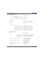
6.1 Feature Set ...................................................................................................................................6-1
6.1.1 Air Filters (Optional) ...........................................................................................................6-1
6.1.2 Lamps...................................................................................................................................6-1
6.2 Input (Source Signal) Compatibility ...........................................................................................6-1
6.3 Control Signal Compatibility ......................................................................................................6-1
6.3.1 Projector Control..................................................................................................................6-1
6.4 Power Requirements ....................................................................................................................6-2
6.4.1 Lamp Specification ..............................................................................................................6-2
6.5 Accessories and Service Components .........................................................................................6-3
6.6 Lens Throw Ratio ........................................................................................................................6-4

Table of Contents
M Series Setup Guide iii
020-100011-07 Rev. 1 (01-2014)
6.7 Regulatory ...................................................................................................................................6-4
6.7.1 Safety ...................................................................................................................................6-4
6.7.2 Electro-Magnetic Compatibility ..........................................................................................6-4
6.7.3 Environmental......................................................................................................................6-4
6.7.4 Marking................................................................................................................................6-4
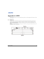
A: GPIO
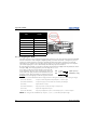
A.1 GPIO Port ...................................................................................................................................A-1
A.1.1 Configuring the GPIO.........................................................................................................A-2


M Series Setup Guide 1-1
020-100011-07 Rev. 1 (01-2014)
1 Introduction
Every effort has been made to ensure the information in this document is accurate and reliable; however, due to
constant research the information in this document is subject to change without notice.
1.1 Purchase Record and Service Contacts
Whether the projector is under warranty or the warranty has expired, Christie’s highly trained and extensive
factory and dealer service network is always available to quickly diagnose and correct projector malfunctions.
Complete service manuals and updates are available for all projectors. Should a problem be encountered with
any part of the projector, contact your dealer. In most cases, servicing is performed on site. If you have
purchased the projector, fill out the information below and keep with your records.
* The serial number can be found on the license label located on the back of the projector.
1.1.1 List of Components
Ensure the following components were received with the projector:
• IR remote keypad (includes two, 1.5V AA batteries and an XLR to mini-stereo cable conversion to wired)
• Line cord
• Lens Mount Security Screw (M6x10mm long, Qty. 2)
• Lens Mount Security Screw (5mm Hex, Qty. 1)
• Warranty Card
• Web Registration Form
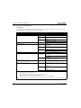
Table 1.1
Dealer:
Dealer or Christie Sales/Service Contact Phone Number:
Projector Serial Number*:
Purchase Date:
Installation Date:
Table 1.2 Ethernet Settings
Default Gateway:
DNS Server:
Projector DLP Address:
Projector Mgmt IP Address:
Subnet Mask:

1-2 M Series Setup Guide
020-100011-07 Rev. 1 (01-2014)
Section 1: Introduction
1.1.2 Key Features
• Up to 14,000 lumens
• HD (1080p) or SXGA+ , WUXGA, or WXGA resolution
• Dual Mercury lamp illumination with 200W, 350W and 450W options
• Dynamic Iris contrast aperture providing up to 10,000:1 contrast ratio
• Ultra-compact design and weighs less than 55lbs
• 10-bit image processor electronics with modular design
• Fully sealed optical system
• Active fan control for minimum noise level
• Selectable, motorized Yellow Notch Filter for expanded color gamut
• User interchangeable projection lenses with no-tool mounting
• PIP and seamless switching
•LiteLOC™ for constant brightness maintenance
• Intelligent Lens System (ILS)
• Motorized lens mount for all models
• Auto-setup feature
• Integrated ChristieNET
• Networking ability through RS-232 and RS-422 connectors
• Status LED display on built-in keypad for easy projector status monitoring
• Control with remote keypad, wired remote, or built-in keypad
• Four input slots for Optional Input Modules
See Section 6 Specifications for a complete list of technical specifications.
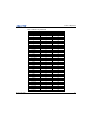
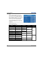
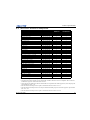
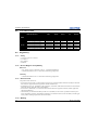
Table 1.3 M Series Projectors
MODEL NAME PART NUMBER
HD14K-M 118-019101-XX
HD10K-M 118-011103-XX
HD6K-M 118-012104-XX
DS+14K-M 118-010113-XX
DS+10K-M 118-013105-XX
DS+6K-M 118-014106-XX
Roadster HD14K-M 118-029102-XX
Roadster HD10K-M 118-021104-XX
Roadster S+14K-M 118-020114-XX
Roadster S+10K-M 118-023106-XX
DLV1920-DL 118-042107-XX
DLV1400-DL 118-044109-XX
WU14K-M 118-011114-XX
WU12K-M 118-015107-XX
WU7K-M 118-016108-XX
Roadster WU14K-M 118-021115-XX

Section 1: Introduction
M Series Setup Guide 1-3
020-100011-07 Rev. 1 (01-2014)
1.2 Safety Warnings and Guidelines
1.2.1 General Precautions
FIRE HAZARD. Keep hands, clothes and all combustible material away from
the concentrated light beam of the projector. Position all cables where they
cannot contact hot surfaces or be pulled or tripped over.
All installation and maintenance procedures must be performed by a Christie
accredited service technician.
Projector must be operated in an environment that meets operating
specifications, as listed in Section 6 Specifications.
1.2.2 AC /Power Precautions
Use only the AC power cord supplied. Do not attempt operation if the AC
supply and cord are not within the specified voltage and power range. Refer
to the license label on the back of the projector or Section 6 Specifications for
rated voltage and power.
The projector is equipped with a 3-wire plug with a grounding pin. This is a
safety feature. If you are unable to insert the plug into the outlet, contact an
electrician to have the outlet replaced. NEVER defeat the safety purpose of
the grounding-type plug.
Do not allow anything to rest on the power cord. Locate the power cord
where persons walking on it or objects rolling over it cannot damage the
cord.
Roadster WU12K-M 118-025108-XX
WX10K-M 118-017109-XX
WX7K-M 118-018100-XX
Table 1.3 M Series Projectors
MODEL NAME PART NUMBER

1-4 M Series Setup Guide
020-100011-07 Rev. 1 (01-2014)
Section 1: Introduction
1.2.3 Lamp Precautions
Never attempt to access the lamp while the lamp is ON. After turning the
lamp OFF, it is crucial that you wait at least 10 minutes before handling the
lamp. This provides sufficient time for the lamp cooling fans to properly cool
the lamp.

M Series Setup Guide 2-1
020-100011-07 Rev. 1 (01-2014)
2 Installation and Setup
2.1 Projector Quick Setup and Installation
The following instructions are for those preferring a quick setup. Refer to the remaining subsections for
detailed setup instructions.
Always power down the projector and disconnect all power sources before
servicing or cleaning.
See the Safety Warnings and Guidelines in 1.2 Safety Warnings and Guidelines.
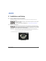
2.1.1 Install a Projection Lens
The projection lens, shipped separately from the projector, must be installed prior to setting up the projector.
Remove the lens plug from the lens opening in the projector before installing
the lens. Retain the lens plug for projector transportation to protect the
optical components from dust and debris.
IMPORTANT! The lens seals the projector, preventing contaminants from entering the interior of the
projector. Never operate a projector without a lens. Remove the rear lens cap from the lens.
Keep the front lens cap on the lens to protect it during installation.
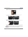
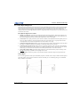
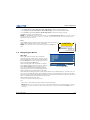
1. Rotate the lens clamp to the OPEN position, as shown.
LOCKING CLAMP
OPEN

2-2 M Series Setup Guide
020-100011-07 Rev. 1 (01-2014)
Section 2: Installation and Setup
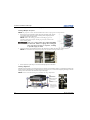
2. Align the lens interface plate with the lens mount. Align the lens electrical connector with the mating
connector on the lens mount. Fully insert the assembly straight into the lens mount opening without
turning. Press using your hand as shown.
NOTE: When installing the lens, ensure that the lens is not inserted at an angle, as this can cause damage.
3. While holding the lens flat against the lens mount, rotate the lens clamp clockwise to lock the lens
assembly in place.
4. Remove the front lens cap.
5. For added stability such as motion applications, fasten the security screws provided with the lens-mount.
NOTE: There are two types of lens plate models.
6. Use a 5mm hex driver to fasten the red security screws provided with the lens mount, or hand tighten the
lens retaining screws attached to the lens.
NOTES: 1) Recommended for heaviest lenses such as 0.73:1 and 1.2:1. 2) The red security screws MUST
be installed when hoisting the projector overhead, or installing the projector in an overhead position.
Use of the lens red security screws or the lens retaining screws is required if
the projector is hoisted or installed in an overhead position.

Section 2: Installation and Setup
M Series Setup Guide 2-3
020-100011-07 Rev. 1 (01-2014)
2.1.2 Position the Projector
2 people are required to safely lift and install the projector.
Place the projector on a sturdy, level surface and position it so that it is perpendicular to the screen at a suitable
distance. The further back the projector is positioned for the screen, the larger the image will be.
To level the projector adjust its 3 feet. With the projector positioned perpendicular to the screen the image will
appear rectangular instead of keystoned.
2.1.3 Connect a Source
The input panel where all source connections are made, is located at the back of the projector. Each input is
clearly labeled for easy identification. Depending on the type of option card installed, connect your source
using the appropriate cable(s), as follows:
•Analog Input Card: Connect 3-, 4-, or 5-wire RGB source to Red/Pr, Green/Y, Blue/Pb, H/C and V using 3,
4 or 5 BNC connectors as required.
•Dual 3G/SD/HD - SDI Input Card: Connect the SDI (Serial Digital Interface) cable to one of the two
inputs, 1-IN or 2-IN. Both standard-definition (SD) and high-definition (HD) signals are accepted and
automatically recognized on either input.
•Dual Link DVI Input Card: Connect a single or dual DVI video signal to the DVI-I connector, an analog
video signal to the DVI-I connector or an analog video signal to the VGA connector. The DVI signal may
contain HDCP (High-Bandwidth Digital Content Protection).
•Twin HDMI Input Card: Connect HDMI (High-Definition Multimedia Interface) cable to one of the two
inputs, 1-IN or 2-IN.
•Video Decoder Input Card: Depending on the source you can apply the following;
• Composite video source to 1-CVBS, using a BNC Cable. Same signal can be used on 4, 5 or 6 when input
is selected as CVBS.
• A component signal on Inputs 4(Pr), 5(Y), 6(Pb) using BNC Connectors.
• S-Video to one of the two, 2-SVID or 3-SVID using S-Video cable.
• S-Video using two BNC cables, with Luma (Y) connected to 4 (Sy) and Chroma (C) connected to 6 (Sc).
•DMX512 Interface Card: Has two 5pin XLR connectors - 1 (input) male and 1 (output) female. If there is
active communications on the DMX512 Interface card the power LED will blink between low intensity and
high intensity.
•Twin DisplayPort Input Card: Accepts DisplayPort 1.1a inputs from one or two DisplayPort sources.
2.1.4 Connect the Line Cord
IMPORTANT!Use the line cord provided with the projector, or ensure you are using a line cord, power plug
and socket that meet the appropriate rating standards. Voltage and current requirements are
listed on the license label, located at the back of the projector.
Connect the projector line cord to the AC receptacle at the AC inlet of the projector, then push the wire clip
over the plug to retain it. This prevents the line cord from inadvertent disconnection. Plug the 3-pronged plug
end into a suitably rated grounded AC receptacle. Switch the projector ON. The switch is located just above
the AC receptacle.
NOTE: This product can be connected to an IT power distribution system.
Do not attempt operation if the AC supply and cord is not within the specified
ratings. On power down, wait 5-10 minutes for the fans to turn OFF before

2-4 M Series Setup Guide
020-100011-07 Rev. 1 (01-2014)
Section 2: Installation and Setup
unplugging the projector. Always switch off the projector before unplugging
the AC line cord.
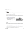
2.1.5 Power up
After the AC Power has been switched on, the LCD display above the keypad indicates “Please wait” and the 4
LED status indicators on the top cover window switch on to amber. These indicate that the projector is
changing its state from powered down to standby. The message “Standby Mode” appears in the display when
the projector has completed its initialization and is ready for power up. The 2 lamp status LEDs will go off to
indicate that the lamps are off. The Power status LED will show amber, indicating that the projector is in
standby mode. The shutter LED will display amber, indicating the shutter is closed. Press and hold the power
button on the keypad or remote for 2 seconds, or press twice quickly. The lamps will power on and the fans will
come on. See Section 3 Operation for a full description of the status indicators.
NOTE: The default settings for the projector are to perform a lens calibration after the insertion of a new lens.
If this is the first time the projector has been powered up with the lens, expect a short period (about 15 seconds)
where the lens will move slightly.
2.1.6 Select a Source
Press one of the input keys on the remote, or on the built-in keypad to select and display the image for the
connected source.
2.1.7 Adjust the Image
Adjust the image settings, such as Brightness, Contrast, Gamma, Focus, Zoom etc. using the direct keys on the
remote, or on the built-in keypad. See Section 3 Operation for more details.
2.2 Detailed Setup and Installation
Always power down the projector and disconnect all power sources before
servicing or cleaning.
See the Safety Warnings and Guidelines in 4 Maintenance. Switch the lamp off
when the door is opened. The lamp doors are provided with clear windows to
indicate when the lamps are on.
2.2.1 Mounting
There are several methods for mounting the projector. In typical front and rear screen installations the projector
can be mounted to a secure and level surface, such as a table or cart. Carts are useful when the projector has to
be moved often. To prevent accidental movement during a presentation, lock the wheels on the cart.
Ceiling Mount
The projector can be inverted and suspended from the ceiling using a specially designed ceiling mount fixture
118-100108-XX. This mounting is recommended for those that want the projector out of plain view or have
limited amount of space for the projector. For more information, contact your dealer.

Section 2: Installation and Setup
M Series Setup Guide 2-5
020-100011-07 Rev. 1 (01-2014)
Use only the Christie approved ceiling mount kit designed for your projector.
Special Mounting
The projector can also be rotated (front-to-back) up to 360 degrees and fixed in a rotated position without
affecting performance. However, the side-to-side tilt limit of the projector must not exceed +/-15 degrees, to
ensure optimal performance of the projector.
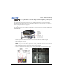
2.2.2 Stacking
The M Series projectors can be stacked up to a maximum of 3 projectors high using the Christie stacking frame
(118-100107-XX).
1. Turn the projector OFF and disconnect the AC power cord after the cooling fans have stopped.
2. Make sure the base plate is flat.
3. Place the projector into the stacking frame.
NOTE: There are two ways of placing the projector into the stacking frame: from the top or from the front.
4. Make sure the pitch is to its maximum, prior to placing the projector from the front.
5. Make sure the bottom base plate of the frame is aligned with the projector.
6. Use a 6 mm Allen key to tighten the (6) M8 bolts securing the base plate to the bottom of the projector.

2-6 M Series Setup Guide
020-100011-07 Rev. 1 (01-2014)
Section 2: Installation and Setup
7. M8 safety point must be used when flying projectors overhead.
Stacking Multiple Projectors
NOTE: The projectors can be stacked and hoisted in either an upright or inverted positions.
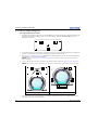
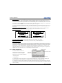
1. With one person positioned on each side of the stacking frame, lift the
top stacking frame onto the bottom stacking frame, aligning all four
stacking legs between the frames.
NOTE: Remove the locking pin from each stacking leg prior to
alignment and ensure the four stacking legs are fully seated on the
lower stacking frame.
Step 2 is a critical safety procedure that MUST
be observed. Failure to engage the locking pin
may cause the projectors to separate, resulting
in possible injury or death.
2. Insert the locking pin through the holes in the stacking legs. Make sure each pin is fully inserted.
NOTE: The steel ball on the end of the pin keeps the pin from releasing inadvertently.
3. When required, repeat steps 1 and 2 for the third projector in the stack.
Stacking Alignment
Stacked projectors must be correctly aligned to one another so the resulting display is optimized. If hoisting the
stack, do so first and then align. To align the image, use pitch, yaw, or roll. Prior to aligning the image, turn the
locking nut to unlock then use the knob to adjust the image.
NOTE: Ensure to lock the locking nut to maintain the image adjustment.

Section 2: Installation and Setup
M Series Setup Guide 2-7
020-100011-07 Rev. 1 (01-2014)
2.2.3 Basic Optical Alignment
Only perform image alignment once the projector is fully assembled and powered up in its final location. Basic
image alignment ensures the image reflected from the DMDs is parallel and well-centered with the lens and
screen. This initial optical alignment is the foundation for optimizing images on the screen and must be
completed before final boresight adjustments. Before beginning, make sure the projector is properly positioned
in relation to the screen.
Basic Optical Alignment Procedure
1. Display a test pattern: Appropriate for analyzing image focus and geometry, such as the “framing” test
pattern showing the cross-hair centered across the image. Press the TEST key on the remote keypad or use
the built-in keypad and press the soft key that displays Test on the LCD display.
2. Course focus: Do a quick preliminary focus and (if available) zoom adjustment with the primary lens. Do
not worry about consistency across the image at this point, just center focus. It is good practice to have
zoom adjustment color and focus adjustment color in the center of its range.
3. Center the image in the lens: Holding a piece of paper at the lens surface, adjust offsets as necessary until
the image is centered within the lens perimeter. A full white field works best for this.
4. Center the image on the screen: If the projector is mounted off center to the screen axis, then offset the
lens as much as required. Aim the projector over slightly towards the center of the screen, but use caution
when doing so, as too much tilt will cause excessive keystone distortion. Lens offset will not.
5. Verify side-to-side leveling: With the framing pattern on screen, double-check projector leveling so the
top edge of the image is parallel to the top edge of the screen.
6. Throw Distance: Ensure the projector is positioned in the throw distance range for the particular lens.
Folded Optics
In rear screen applications where space behind the projector is limited, a mirror may be used to fold the optical
path. The position of the projector and mirror must be accurately set - if considering this type of installation
call your dealer for assistance.

2-8 M Series Setup Guide
020-100011-07 Rev. 1 (01-2014)
Section 2: Installation and Setup
2.2.4 Advanced Optical Alignment
Boresight Alignment Procedure
1. Display the boresight test pattern by pressing the TEST key on the remote keypad or use the built-in keypad
and press the soft key that displays “Test” on the LCD display. Press the UP ARROW KEY to cycle to
Boresight, then Enter.
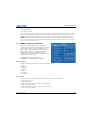
2. Focus the image on cross-hair image I. Evaluate the focus on cross-hair image II and III. If all 3 images are
in focus, no further action is required. If boresight is required, continue to step 3.
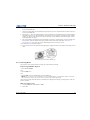
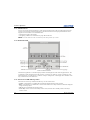
3. See Figure 2-1 Cross-Hair Pattern to understand how the adjustment screws on the lens mount affect the
corresponding cross-hairs on the test pattern.
NOTE: The cap screw, (Figure 2-2 Screw Locations) may be under a plastic cap. Remove and retain
before adjusting.
4. Use a 5 mm hex driver to loosen 3 setscrews on the lens mount as shown in Figure 2-2 Screw Locations.
NOTE: The setscrews must be backed out several turns to avoid contact with the inner lens mount plate.
5. Fine tune the focus of cross-hair pattern I by adjusting the appropriate cap screw. Adjust until the cross-
hair image is in focus with minimal flare.
FIGURE 2-1 CROSS-HAIR PATTERN FIGURE 2-2 SCREW LOCATIONS
A
B
AB
Capscrew
Setscrew
A
B
A
B
Page is loading ...
Page is loading ...
Page is loading ...
Page is loading ...
Page is loading ...
Page is loading ...
Page is loading ...
Page is loading ...
Page is loading ...
Page is loading ...
Page is loading ...
Page is loading ...
Page is loading ...
Page is loading ...
Page is loading ...
Page is loading ...
Page is loading ...
Page is loading ...
Page is loading ...
Page is loading ...
Page is loading ...
Page is loading ...
Page is loading ...
Page is loading ...
Page is loading ...
Page is loading ...
Page is loading ...
Page is loading ...
Page is loading ...
Page is loading ...
Page is loading ...
Page is loading ...
Page is loading ...
Page is loading ...
Page is loading ...
Page is loading ...
-
 1
1
-
 2
2
-
 3
3
-
 4
4
-
 5
5
-
 6
6
-
 7
7
-
 8
8
-
 9
9
-
 10
10
-
 11
11
-
 12
12
-
 13
13
-
 14
14
-
 15
15
-
 16
16
-
 17
17
-
 18
18
-
 19
19
-
 20
20
-
 21
21
-
 22
22
-
 23
23
-
 24
24
-
 25
25
-
 26
26
-
 27
27
-
 28
28
-
 29
29
-
 30
30
-
 31
31
-
 32
32
-
 33
33
-
 34
34
-
 35
35
-
 36
36
-
 37
37
-
 38
38
-
 39
39
-
 40
40
-
 41
41
-
 42
42
-
 43
43
-
 44
44
-
 45
45
-
 46
46
-
 47
47
-
 48
48
-
 49
49
-
 50
50
-
 51
51
-
 52
52
-
 53
53
-
 54
54
-
 55
55
-
 56
56


Christie HD14K-M Installation guide
- Category
- Data projectors
- Type
- Installation guide
Ask a question and I''ll find the answer in the document
Finding information in a document is now easier with AI
Related papers
-
Christie Roadster S+10K-M User manual
-
Christie Mirage HD14K-M User manual
-
Christie WU12K-M User manual
-
Christie J series 2.4kW User manual
-
-
Christie Roadster HD10K-M User manual
-
-
-
-