Page is loading ...

Instruction Manual
thermoMETER CT
CT-SF
CTF
CTH
CTM-1
CTM-2
CTM-3
CTP-3
CTP-7

MICRO-EPSILON
MESSTECHNIK
GmbH & Co. KG
Königbacher Strasse 15
94496 Ortenburg / Germany
Tel. +49 (0) 8542 / 168-0
Fax +49 (0) 8542 / 168-90
www.micro-epsilon.com
Certified acc. to DIN EN ISO 9001: 2008
Infrared sensor

thermoMETER CT
Contents
1. Safety ........................................................................................................................................ 7
1.1 Symbols Used ................................................................................................................................................. 7
1.2 Warnings .......................................................................................................................................................... 7
1.3 Notes on CE Identification ............................................................................................................................... 8
1.4 Proper Use ....................................................................................................................................................... 9
1.5 Proper Environment ......................................................................................................................................... 9
2. Technical Data ........................................................................................................................ 10
2.1 Functional Principle ....................................................................................................................................... 10
2.2 Sensor Models ............................................................................................................................................... 11
2.3 General Specifications ................................................................................................................................... 12
2.4 Electrical Specifications ................................................................................................................................. 13
2.5 Measurement Specifications ........................................................................................................................ 14
2.5.1 CT Model ...................................................................................................................................... 14
2.5.2 CTF / CTH Models ........................................................................................................................ 15
2.5.3 CTM Models ................................................................................................................................. 16
2.5.4 CTP Models .................................................................................................................................. 19
3. Delivery ................................................................................................................................... 20
3.1 Unpacking ...................................................................................................................................................... 20
3.2 Storage .......................................................................................................................................................... 20
4. Optical Charts ......................................................................................................................... 21
5. Mechanical Installation .......................................................................................................... 29
6. Electrical Installation .............................................................................................................. 31
6.1 Cable Connections ........................................................................................................................................ 31
6.1.1 Pin Assignment ............................................................................................................................. 31
6.1.1.1 CT-SF02, CT-SF15, CT-SF22, CTF-SF15, CTF-SF25, CTH-SF02, CTH-SF10,
CTP-7 and CTP-3 Models ............................................................................................ 31
6.1.1.2 CTM-1, CTM-2, CTM-3 Models ................................................................................... 32
6.2 Power Supply ................................................................................................................................................. 32
6.3 Cable Assembling .......................................................................................................................................... 33
6.4 Ground Connection ....................................................................................................................................... 34

thermoMETER CT
6.5 Exchange of the Sensor ................................................................................................................................ 35
6.5.1 Entering of the Calibration Code .................................................................................................. 35
6.5.2 Sensor Cable ................................................................................................................................ 36
7. Outputs and Inputs ................................................................................................................. 37
7.1 Analog Outputs .............................................................................................................................................. 37
7.1.1 Output Channel 1 ......................................................................................................................... 37
7.1.2 Output Channel 2 (only CT-SF02, CT-SF15, CT-SF22, CTH, CTP-7 and CTP-3) ......................... 37
7.2 Digital Interfaces ............................................................................................................................................ 38
7.2.1 USB Interface ............................................................................................................................... 39
7.2.1.1 Installation ................................................................................................................... 39
7.2.1.2 Driver Installation of Interface...................................................................................... 39
7.2.2 RS232 Interface ............................................................................................................................ 40
7.2.2.1 Installation ................................................................................................................... 40
7.2.2.2 Software Installation .................................................................................................... 40
7.2.3 RS485 Interface ............................................................................................................................ 41
7.2.3.1 Installation ................................................................................................................... 41
7.2.3.2 Sensor Installation ....................................................................................................... 42
7.2.4 Profibus Interface ......................................................................................................................... 43
7.2.4.1 Installation ................................................................................................................... 43
7.2.4.2 Commissioning Profibus ............................................................................................. 44
7.2.5 CAN BUS Interface ....................................................................................................................... 45
7.2.6 Ethernet Interface ......................................................................................................................... 47
7.2.6.1 Installation ................................................................................................................... 47
7.2.6.2 Installation of the Ethernet Adapter in a Network ....................................................... 48
7.2.6.3 Uninstalling the Ethernet Adapter in a Network .......................................................... 51
7.2.6.4 Direct Connection to a PC .......................................................................................... 52
7.2.6.5 Settings inside the CompactConnect Software .......................................................... 57
7.2.6.7 Resetting the Ethernet Adapter ................................................................................... 58
7.3 Relays Outputs .............................................................................................................................................. 59
7.4 Functional Inputs ........................................................................................................................................... 60
7.5 Alarms ............................................................................................................................................................ 61
7.5.1 Output Channel 1 and 2 (Channel 2 on CT-SF / CTP-7 and CTP-3) ............................................ 61
7.5.2 Visual Alarms ................................................................................................................................ 61

thermoMETER CT
8. Operating ................................................................................................................................ 62
8.1 Restoring Factory Setting .............................................................................................................................. 62
8.2 Sensor Setup ................................................................................................................................................. 64
8.3 Explanation to the Menu Items ...................................................................................................................... 65
8.4 Error Messages .............................................................................................................................................. 68
8.4.1 CT-SF02, CT-SF15, CT-SF22, CTH and CTP Models ................................................................... 68
8.4.2 CTM-1, CTM-2, CTM-3 Models..................................................................................................... 68
9. Instructions for Operation...................................................................................................... 69
9.1 Cleaning ......................................................................................................................................................... 69
10. CompactConnect Software .................................................................................................... 70
10.1 System Requirements ................................................................................................................................... 70
10.2 Main Features ................................................................................................................................................ 70
11. Communication Settings ........................................................................................................ 71
11.1 Serial Interface ............................................................................................................................................... 71
11.2 Protocol .......................................................................................................................................................... 71
11.3 ASCII Protocol .............................................................................................................................................. 71
11.4 Saving of Parameter Settings ........................................................................................................................ 72
12. Basics of Infrared Thermometry ............................................................................................ 73
13. Emissivity ................................................................................................................................ 74
13.1 Definition ........................................................................................................................................................ 74
13.2 Determination of Unknown Emissivity ........................................................................................................... 74
13.3 Characteristic Emissivity ................................................................................................................................ 75
14. Warranty .................................................................................................................................. 76
15. Service, Repair ....................................................................................................................... 77
16. Decommissioning, Disposal .................................................................................................. 77

thermoMETER CT
Appendix
A 1 Accessories ............................................................................................................................ 78
A 1.1 Mounting Accessories ................................................................................................................................... 78
A 1.2 Air Purge Collars ............................................................................................................................................ 79
A 1.2.1 Standard Air Purge Collar ............................................................................................................ 79
A 1.2.2 Laminar Air Purge Collar .............................................................................................................. 80
A 1.3 CF Lens and Protective Window ................................................................................................................... 81
A 1.4 Further Accessories ....................................................................................................................................... 84
A 1.4.1 Right Angle Mirror......................................................................................................................... 84
A 1.4.2 Rail Mount Adapter for Controller ................................................................................................ 85
A 1.4.3 Tilt Assembly for CT Sensors ....................................................................................................... 85
A 1.4.4 Laser Sighting Tool ....................................................................................................................... 86
A 1.4.5 OEM Laser Sighting Tool .............................................................................................................. 87
A 1.4.6 Massive Housing .......................................................................................................................... 88
A 1.4.7 Accessories for Massive Housing ................................................................................................ 89
A 1.4.8 Pipe Adapter and Sighting Tubes ................................................................................................ 90
A 2 Factory Settings ..................................................................................................................... 91
A 3 Emissivity Table Metals .......................................................................................................... 93
A 4 Emissivity Table Non Metals .................................................................................................. 96
A 5 Smart Averaging ..................................................................................................................... 98

Page 7
Safety
thermoMETER CT
1. Safety
The handling of the system assumes knowledge of the instruction manual.
1.1 Symbols Used
The following symbols are used in the instruction manual.
Indicates a hazardous situation which, if not avoided, may result in minor or mode-
rate injuries.
Indicates a situation which, if not avoided, may lead to property damage
Indicates a user action.
i
Indicates a user tip.
Measure
Indicates a hardware or a button/menu in the software
1.2 Warnings
Connect the power supply and the display/output device in accordance with the safety regulations for electri-
cal equipment.
> Danger of injury
> Damage to or destruction of the sensor and/or controller
Avoid shock and vibration to the sensor and the controller.
> Damage to or destruction of the sensor and/or controller
The power supply must not exceed the specified limits.
> Damage to or destruction of the sensor and/or controller
Protect the sensor cable against damage.
> Destruction of the sensor, Failure of the measuring device

Page 8
Safety
thermoMETER CT
Do not kink the sensor cable and bend the sensor cable in tight radius. The minimum bending radius is
14 mm (static). A dynamic movement is not allowed.
> Damage to the sensor cable, failure of the measuring device
No solvent-based cleaning agents may have an effect on the sensor (neither for the optics nor the housing)
> Damage to or destruction of the sensor
1.3 Notes on CE Identification
The following applies to the thermoMETER CT:
- EU directive 2004/108/EC
- EU directive 2011/65/EU, “RoHS“ category 9
Products which carry the CE mark satisfy the requirements of the quoted EU directives and the European
standards (EN) listed therein. The EC declaration of conformity is kept available according to EC regulation,
article 10 by the authorities responsible at
MICRO-EPSILON MESSTECHNIK
GmbH & Co. KG
Königbacher Straße 15
94496 Ortenburg / Germany
The system is designed for use in industry and laboratory and satisfies the requirements.

Page 9
Safety
thermoMETER CT
1.4 Proper Use
- The thermoMETER CT is designed for use in industrial and laboratory areas. It is used for non-contact
temperature measurement.
- The system may only be operated within the limits specified in the technical data, see Chap. 2..
- Use the system in such a way that in case of malfunctions or failure personnel or machinery are not endan-
gered.
- Take additional precautions for safety and damage prevention for safety-related applications.
1.5 Proper Environment
- Protection class:
Sensor: IP 65 (NEMA 4)
Controller: IP 65 (NEMA 4)
- Operating temperature:
Sensor: See also Chapter Measurement Specification, see Chap. 2.5
Controller: 0 ... 85 °C (+32 ... +185 °F)
Avoid abrupt changes of the operating temperature of both the sensor and the controller.
> Inaccurate measuring values
- Storage temperature:
Sensor: See also Chapter Measurement Specification, see Chap. 2.5
Controller: -40 ... 85 °C (-40 ... +185 °F)
- Humidity: 10 ... 95 %, non-condensing

Page 10
Technical Data
thermoMETER CT
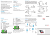
2. Technical Data
2.1 Functional Principle
The sensors of the thermoMETER CT series are non-contact measuring infrared temperature sensors. They
calculate the surface temperature based on the emitted infrared energy of objects, see Chap. 12.
The sensor housing of the thermoMETER CT is made from stainless steel (protection class IP 65/ NEMA 4),
the controller is placed in a separate box made of die casting zinc.
i
The thermoMETER CT sensor is a sensitive optical system. Please only use the thread for mechanical
installation.
Avoid mechanical violence on the sensor.
> Destruction of the system

Page 11
Technical Data
thermoMETER CT
2.2 Sensor Models
Model Model codes Measuring range Spectral response Typical applications
CT CT-SF02 / CT-SF15 /
CT-SF22
-50 to 975 °C 8 - 14 μm Non-metallic surfaces
CTF CTF-SF15 /
CTF-SF25
-50 to 975 °C 8 - 14 μm Fast processes
CTH CTH-SF02 /
CTH-SF10
-40 to 975 °C 8 - 14 μm High ambient temperatures
(to 250 °C)
CTM-1SF CTM-1SF40 /
CTM-1SF75 /
CTM-1SF75H1
485 to 2200 °C 1 μm Metals and ceramic sur-
faces
CTM-2SF CTM-2SF40 /
CTM-2SF75
CTM-2SF75H1
250 to 2200 °C 1.6 μm Metals and ceramic sur-
faces
CTM-3SF CTM-3SF22 /
CTM-3SF33 /
CTM-3SF75H1 /
CTM-3SF75H2 /
CTM-3SF75H3
50 to 1800 °C 2.3 μm Metals at low object tem-
peratures (from 50 °C)
CTP-7 CTP-7SF10 0 to 710 °C 7.9 μm Temperature of thin film
plastics
CTP-3 CTP-3SF15 50 to 400 °C 3.43 μm
In the following chapters of this manual you will find only the short model codes. On the CTM-1, CTM-2 and
CTM-3 models the whole measuring range is split into several sub ranges.

Page 12
Technical Data
thermoMETER CT
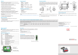
2.3 General Specifications
Sensor Controller
Protection class IP 65
Operating temperature See also Chapter Measurement
Specification, see Chap. 2.5
0 ... 85 °C (+32 ... +185 °F)
Only CTP-3: 0 ... 75 °C
(+32 ... +167 °F)
Storage temperature See also Chapter Measurement
Specification, see Chap. 2.5
-40 ... 85 °C (-40 ... +185 °F)
Relative humidity 10 ... 95 %, non-condensing
Material Stainless steel Die casting zinc
Dimensions 28 mm x 14 mm, M12x1 89 mm x 70 mm x 30 mm
Dimensions
CTH, CTP-7, CTP-3
55 mm x 29.5 mm, M18x1
(with massive housing)
89 mm x 70 mm x 30 mm
Weight 40 g (CTP-7 and CTP-3: 200 g) 420 g
Cable length 1 m (only CT-SF02, CT-SF15, CT-SF22, CT-SF15, CT-SF22),
3 m (standard at CTH, CTM
1
, CTP-7 and CTP-3),
8 m, 15 m
Cable diameter 2.8 mm
Ambient temperature
cable
Max. 180 °C
[High temperature cable for CtH: 250 °C]
Vibration IEC 68-2-6: 3 g 11 - 200 Hz, any axis
Shock IEC 68-2-27: 50 g, 11 ms, any axis
CompactConnect
Software
optional
1) The CTM-3 models are only available with 3 m cable.

Page 13
Technical Data
thermoMETER CT
2.4 Electrical Specifications
Power supply 8 - 36 VDC
Current draw max. 100 mA
Outputs/ analog
Channel 1
selectable: 0/4 - 20 mA, 0 - 5/10 V, thermocouple (J or K) or
alarm output
(Signal source: object temperature)
Channel 2
(only CT-SF02, CT-SF15, CT-SF22,
CTP-7, CTP-3)
Sensor temperature [-20 ... 180 °C], [-20 ... 250 °C at CTH-SF02
or CTH-SF10], [0 ... 75 °C at CTP-3] as 0 – 5 V or 0 – 10 output or
alarm output
(Signal source switchable to object temperature or controller tem-
perature if used as alarm output)
Alarm output Open collector Output on Pin AL2 [24 V/50 mA]
Output impedances mA max. loop resistance 500 Ω (at 8 - 36 VDC)
mV min. 100 kΩ load impedance
Thermocouple 20 Ω
Digital interfaces USB, RS232, RS485, CAN, Profibus DP, Ethernet
(optional plug-in modules)
Relay outputs 2 x 60 VDC/42 VAC
RMS
, 0.4 A;
potential free (optional plug-in modules)
Functional inputs F1 up to F3; software programmable for the following functions:
- external emissivity adjustment
- ambient temperature compensation,
- trigger (reset of hold functions)
Input impedance F2 and F3: 43 kΩ

Page 14
Technical Data
thermoMETER CT
2.5 Measurement Specifications
2.5.1 CT Model
Model CT-SF02 CT-SF15 CT-SF22
Temperature range (scalable) -50 ... 600 °C -50 ... 600 °C -50 ... 975 °C
Operating temperature (sensor) -20 ... 130 °C -20 ...180 °C -20 ...180 °C
Storage temperature (sensor) -40 ... 130 °C -20 ... 180 °C -20 ... 180 °C
Spectral range 8 ... 14 μm
Optical resolution 2:1 15:1 22:1
System accuracy
1 2
±1 °C or ±1 %
3
Repeatability
1
±0.5 °C or ±0.5 %
3
Temperature coefficient
5
±0.05 K/ K or ±0.05 %/ K (whichever is greater)
Temperature resolution (NETD)
3 4
0.1 K 0.05 K
Response time (95 % signal) 150 ms
Warm-up time 10 min
Emissivity/ gain 0.100 ... 1.100 (adjustable via programming keys or software)
Transmissivity 0.100 ... 1.100 (adjustable via programming keys or software)
Signal processing Average, peak hold, valley hold
(adjustable via programming keys or software)
Software (optional) CompactConnect
1) At operating temperature 23 ±5 °C; whichever is greater.
2) Accuracy for thermocouple output: ±2.5 °C or ±1 %
3) At object temperatures > 0 °C; e = 1
4) At time constant 200 ms and an object temperature of 25 °C
5) For ambient temperatures (sensor): 18 °C ≤ sensor ≤ 28 °C
i
On the CT models CT-SF02 the sensor cable must not be moved during the measurement.

Page 15
Technical Data
thermoMETER CT
2.5.2 CTF / CTH Models
Model CTF-SF15 CTF-SF25 CTH-SF02 CTH-SF10
Temperature range (scalable) -50 ... 975 °C -50 ... 975 °C -40 ... 975 °C -40 ... 975 °C
Operating temperature (sensor) -20 ... 120 °C -20 ... 120 °C -20 ... 250 °C -20 ... 250 °C
Storage temperature (sensor) -40 ... 120 °C -40 ... 120 °C -40 ... 250 °C -40 ... 250 °C
Spectral range 8 ... 14 μm
Optical resolution 15:1 25:1 2:1 10:1
System accuracy
1 2
±2 °C or ±1 %
3
±1,5 °C or ±1 %
3
Repeatability
1
±0,75 °C or ±0,75 %
3
±0,5 °C or ±0,5 %
3
Temperature coefficient
5
±0.05 K/ K or ±0.05 %/ K (whichever is greater)
Temperature resolution (NETD)
3 4
0.2 K 0.4 K 0.25 K 0.25 K
Response time (95 % signal) 9 ms 6 ms 100 ms 100 ms
Acquisition time (50 % signal) 4 ms 3 ms - -
Warm-up time 10 min
Emissivity / gain 0.100 ... 1.100 (adjustable via programming keys or software)
Transmissivity 0.100 ... 1.100 (adjustable via programming keys or software)
Signal processing Average, peak hold, valley hold
(adjustable via programming keys or software)
Software (optional) CompactConnect
1) At operating temperature 23 ±5 °C; whichever is greater.
2) Accuracy for thermocouple output: ±2.5 °C or ±1 %
3) At object temperatures ≥ 20 °C; e = 1
4) At time constant 100 ms with smart averaging and an object temperature of 25 °C
5) For ambient temperatures (sensor): 18 °C ≤ sensor ≤ 28 °C
i
On the CTH models CTH-SF02/ CTH-SF10 the sensor cable must not be moved during the measure-
ment.

Page 16
Technical Data
thermoMETER CT
2.5.3 CTM Models
Model CTM-1SF40 CTM-1SF75 CTM-1SF75H1 CTM-2SF40
Temperature range
(scalable)
485 ... 1050 °C 650 ... 1800 °C 800 ... 2200 °C 250 ... 800 °C
Operating temperature
(sensor)
-20 ... 100 °C -20 ... 100 °C -20 ... 100 °C -20 ... 125 °C
Operating temperature
(sensor)
-40 ... 100 °C -40 ... 100 °C -40 ... 100 °C -40 ... 125 °C
Spectral range 1 μm 1,6 μm
Optical resolution 40:1 75:1 75:1 40:1
System accuracy
1 2
± (0.3 % of reading + 2 °C)
3
Repeatability
1
± (0.1 % of reading + 1 °C)
3
Temperature coefficient
5
±0.05 K/K or ±0.05 %/K (whichever is greater)
Temperature resolution 0.1 °C
3
Exposure time (90 % signal) 1 ms
4
Emissivity / gain 0.100 ... 1.100 (adjustable via programming keys or software)
Transmissivity 0.100 ... 1.100 (adjustable via programming keys or software)
Signal processing Average, peak hold, valley hold (adjustable via programming keys or software)
Software (optional) CompactConnect
1) At operating temperature 23 ±5 °C.
2) Accuracy for thermocouple output: ±2,5 °C or ±1 %
3) e = 1 / Response time 1 s
4) With dynamic adaptation at low signal levels
5) For ambient temperatures (sensor): 18 °C ≤ sensor ≤ 28 °C

Page 17
Technical Data
thermoMETER CT
Model CTM-2SF75 CTM-2SF75H1 CTM-3SF22 CTM-3SF33
Temperature range (scalable)
1
385 ... 1600 °C 490 ... 2000 °C 50 ... 400 °C
1
100 ... 600 °C
1
Operating temperature Sensor -20 ... 125 °C -20 ... 85 °C
Controller 0 ... 85 °C
Storage temperature Sensor -40 ... 125 °C -40 ... 85 °C
Controller -40 ... 85 °C
Spectral range 1.6 μm 2.3 μm
Optical resolution 75:1 75:1 22:1 33:1
System accuracy
2 3
± (0.3 % T
MESS
+ 2 °C)
4
Repeatability
2
± (0.1 % T
MESS
+ 2 °C)
4
Temperature coefficient
6
±0.05 K/K or ±0.05 %/K (whichever is greater)
Temperature resolution 0.1 °C
4
Exposure time (90 % signal) 1 ms
5
Emissivity / gain 0.100 ... 1.100 (adjustable via programming keys or software)
Transmissivity 0.100 ... 1.100 (adjustable via programming keys or software)
Signal processing Average, peak hold, valley hold (adjustable via programming keys or software)
Software (optional) CompactConnect
1) TObject > TSensor+25 °C
2) At ambient temperature 23 ±5 °C
3) Accuracy for thermocouple output: ±2.5°C or ±1 %
4) e = 1/ Response time 1 s
5) With dynamic adaptation at low signal levels
5) For ambient temperatures (sensor): 18 °C ≤ sensor ≤ 28 °C

Page 18
Technical Data
thermoMETER CT
Model CTM-3SF75H1 CTM-3SF75H2 CTM-3SF75H3
Temperature range (scalable) 150 ... 1000 °C 200 ... 1500 °C 250 ... 1800 °C
Operating temperature Sensor -20 ... 85 °C
Controller 0 ... 85 °C
Storage temperature Sensor -40 ... 85 °C
Controller -40 ... 85 °C
Spectral range 2.3 μm
Optical resolution 75:1
System accuracy
1 2
± (0.3 % T
of rading
+ 2 °C)
Response time
1
± (0.1 % T
of reading
+ 1 °C)
3
Temperature coefficient
5
±0.05 K/K or ±0.05 %/K (whichever is greater)
Temperature resolution 0.1 °C
3
Response time (90 % signal) 1 ms
4
Emissivity / gain 0.100...1.100 (adjustable via programming keys or software)
Transmissivity 0.100...1.100 (adjustable via programming keys or software)
Signal processing Average, peak hold, valley hold (adjustable via programming
keys or software)
Software (optional) CompactConnect
1) At ambient temperature 23 ±5 °C; whichever is greater (CTP-7)
2) Accuracy for thermocouple output: ±2.5 °C or ±1 %
3) e = 1 / Response time 1 s
4) With dynamic adaptation at low signal levels
5) For ambient temperatures (sensor): 18 °C ≤ sensor ≤ 28 °C

Page 19
Technical Data
thermoMETER CT
2.5.4 CTP Models
Model CTP-7 CTP-3
Temperature range (scalable)
6
0 ... 710 °C 50 ... 400 °C
Operating temperature Sensor -20 ... 85 °C -0 ... 75 °C
Controller 0 ... 85 °C -0 ... 75 °C
Storage temperature Sensor -40 ... 85 °C
Controller -40 ... 85 °C
Spectral range 7.9 μm 3.43 μm
Optical resolution 10:1 15:1
System accuracy
1 2
±1.5 °C or
±1 %
3 5
±3 °C or
±1 %
3 5
Repeatability
1
±0.5 °C or
±0.5 %
3 5
±1.5 °C
Temperature coefficient
5
±0.05 K/K or ±0.05 %/K (which-
ever is greater)
-----
Temperature resolution 0.5 °C
3
0.1 °C
Response time (90 % signal) 150 ms 100 ms
Emissivity / gain 0.100 ... 1.100 (adjustable via programming keys or software)
Transmissivity 0.100 ... 1.100 (adjustable via programming keys or software)
Signal processing Average, peak hold, valley hold
(adjustable via programming keys or software); extended hold
function with threshold and hysteresis
Software (optional) CompactConnect
1) At ambient temperature 23 ±5 °C; whichever is greater (CTP-7)
2) Accuracy for thermocouple output: ±2.5 °C or ±1 %
3) e = 1 / Response time 1 s
4) With dynamic adaptation at low signal levels
5) For ambient temperatures (sensor): 18 °C ≤ sensor ≤ 28 °C
6) When CTP-3: Adjustable via programming keys or software

Page 20
Delivery
thermoMETER CT
3. Delivery
3.1 Unpacking
1 thermoMETER CT sensor
1 Controller
1 Connection cable
1 Mounting nut
1 Instruction manual
Check the delivery for completeness and shipping damage immediately after unpacking.
In case of damage or missing parts, please contact the manufacturer or supplier.
Optional accessories you will find in the Chapters
- Mounting Accessories, see Chap. A 1.1
- Air Purge Collars, see Chap. A 1.2
- CF Lens and Protective Window, see Chap. A 1.3
- Further Accessories, see Chap. A 1.4
3.2 Storage
- Storage temperature, see Chap. 2.5.
- Humidity: 10 ... 95 %, non-condensing
/