RAB Lighting IVGT5U-30L740WU/WS2 Operating instructions

Type
Operating instructions
IVEPARK™ INSTALLATION INSTRUCTIONS
Thank you for buying RAB lighting fi xtures. Our goal is to design the best quality products to get the job done right. We’d like to hear your comments.
Call the Marketing Department at 888-RAB-1000 or email: marketing@rablighting.com
Note: These instructions do not cover all details or variations in equipment nor do they provide for every possible situation during installation, operation or maintenance.
To reduce the risk of electric shock, disconnect both normal and emergency power supplies and converter connector of the emergency ballast before servicing. Do not attempt to service
the emergency ballast. The use of accessory equipment may cause an unsafe condition. Do not use this product for other than intended use. Refer any servicing indicated by these checks
to a Qualifi ed Service Personnel.
Easy Answers
rablighting.com
Visit our website for product info
Tech Help Line
Call our experts - 888 722-1000
e-mail
Answered promptly - sales@rablighting.com
Free Lighting Layouts
Answered online or by request
© 2018 RAB LIGHTING Inc.
Northvale, New Jersey 07647 USA
IVEPARK 1018
IMPORTANT
READ CAREFULLY BEFORE INSTALLING FIXTURE. RETAIN THESE INSTRUCTIONS FOR FUTURE REFERENCE.
Fixtures must be wired in accordance with the National Electrical Code and all applicable local codes. Proper grounding is
required for safety. THIS PRODUCT MUST BE INSTALLED IN ACCORDANCE WITH THE APPLICABLE INSTALLATION CODE BY A
PERSON FAMILIAR WITH THE CONSTRUCTION AND OPERATION OF THE PRODUCT AND THE HAZARDS INVOLVED.
WARNING: Make certain power is OFF before installing or maintaining fi xture. No user-serviceable parts inside.
CAUTION: For a proper weatherproof function, all gaskets must be seated properly and all screws inserted and tightened
rmly. Apply weatherproof silicone sealant around the edge of the Junction Box. This is especially important with an un-
even ceiling surface. Silicone all plugs and unused conduit entries.
IVEPARK
(SURFACE MOUNT)
TRUNNION MOUNT
WALL MOUNT
UNIVERSAL POLE MOUNT
CEILING MOUNTING
Fixture is suitable for outdoor applications in wet locations.
1. Remove the ceiling mount from the back of the fi xture by rotating
counter-clockwise.
2. Install the ceiling mount to the ceiling by knocking out (4) Knock
Out Locations as marked in Fig. 1b. Use the appropriate mount-
ing hardware for the mounting surface (Fig. 1). May alternately be
mounted to recessed junction boxes.
3. For hands-free wiring hang the fi xture using the included tether.
Connect supply wires to Fixture Wires. Use appropriate UL ap-
proved wire connectors as required by code to complete wiring.
4. Attach fi xture to ceiling mount by raising the fi xture up to the ceil-
ing mount and rotating clockwise to lock into place
5. If mounting surface is irregular, use caulk to seal any gaps around
Junction Box.
PENDANT MOUNTING
Fixture can be mounted to a 1/2” or 3/4” NPS Pendant. 1/2” to 3/4” NPS
Adaptor is included.
1. Feed supply wires through Pendant (supplied by others).
2. Remove the ceiling mount from the back of the fi xture by rotating
counter-clockwise.
3. Mount the ceiling mount to the Pendant. For 3/4” Pendant, remove
the NPS Adaptor.
4. For hands-free wiring hang the fi xture using the included tether.
Connect supply wires to Fixture Wires. Use appropriate UL approved
wire connectors as required by code to complete wiring.
5. Attach fi xture to ceiling mount by raising the fi xture up to the
ceiling mount and rotating clockwise to lock into place.
FIG. 1
FIG. 1b
FIG. 2
3-1/4”
82.6mm
3-1/4”
82.6mm
Ø 4-1/8”
104.8mm
Ø 5-1/4”
133.4mm
NPS Adapter
Ceiling Adapter
Ceiling Mount
(4) Knock Out
Locations
IVEPARK™ INSTALLATION INSTRUCTIONS
Thank you for buying RAB lighting fi xtures. Our goal is to design the best quality products to get the job done right. We’d like to hear your comments.
Call the Marketing Department at 888-RAB-1000 or email: marketing@rablighting.com
Easy Answers
rablighting.com
Visit our website for product info
Tech Help Line
Call our experts - 888 722-1000
e-mail
Answered promptly - sales@rablighting.com
Free Lighting Layouts
Answered online or by request
© 2018 RAB LIGHTING Inc.
Northvale, New Jersey 07647 USA
IVEPARK 1018
POLE MOUNTING
MOUNTING THE UNIVERSAL ARM ON THE FIXTURE
1. Remove the Arm Cover from the Arm.
2. Attach ceiling mount to arm using screws (not provided)
3. Feed wires from Fixture through ceiling mount into Arm.
4. Line up Arm and Fixture. Attach fi xture to secured ceil-
ing cover with a clockwise twist
SQUARE POLE BRACKET MOUNT
1. Remove Round pole adaptor and RPA gasket.
2. Place the Bolster plate inside the pole.
3. Place the bracket to match the holes on the pole
(as shown in fi g 3)
4. Feed supply wires from the pole through the Bracket to
be connected to the Arm.
5. Place fl at washers, lock washers and nuts on the Short
3/8-16 bolts tighten to the pole
ROUND POLE BRACKET MOUNT
1. Place Round Pole Adaptor (RPA) and RPA Gasket be-
tween the fi xture and drilled Pole as shown in Fig.4.
2. Line up the holes of the Gaskets and Round Pole Adap-
tor with top hole in the pole drilling pattern.
3. Feed supply wires from the pole through the Bracket to
be connected to the Arm.
4. Place long 3/8” Bolts provided through the top hole
of the RPA and Gaskets to the Round Pole thread into
Bolster Plate
MOUNTING FIXTURE TO THE POLE
1. Remove the Arm Cover from the Arm.
2. Feed supply wires which are already pulled out from the
pole through the bracket into the Arm.
3. Make necessary connections inside the Arm and knot
wires for strain relief.
4. Slide the metal hanger plates at the back of the Arm to
the mounting hooks of the bracket on the pole,to secure
the fi xture to the pole. (as shown in fi g 5)
5. Replace the Arm Cover. Be sure the Gasket on Arm Cover
is in place. Tighten Screws and add the Plugs. Secure
Pole cap. Tighten Set screw at the bottom of the arm
Note: These instructions do not cover all details or variations in equipment nor do they provide for every possible situation during installation, operation or maintenance.
To reduce the risk of electric shock, disconnect both normal and emergency power supplies and converter connector of the emergency ballast before servicing. Do not attempt to service
the emergency ballast. The use of accessory equipment may cause an unsafe condition. Do not use this product for other than intended use. Refer any servicing indicated by these checks
to a Qualifi ed Service Personnel.
Long 3/8” bolts
Short 3/8” bolts
Square Pole
Round Pole
Round Pole Adaptor(RPA)
RPA Gasket
Bolster Plate
Bracket
Bolster Plate
FIG. 3
FIG. 4
FIG. 5
Bracket
Set Screw
IVEPARK™ INSTALLATION INSTRUCTIONS
Thank you for buying RAB lighting fi xtures. Our goal is to design the best quality products to get the job done right. We’d like to hear your comments.
Call the Marketing Department at 888-RAB-1000 or email: marketing@rablighting.com
Easy Answers
rablighting.com
Visit our website for product info
Tech Help Line
Call our experts - 888 722-1000
e-mail
Answered promptly - sales@rablighting.com
Free Lighting Layouts
Answered online or by request
© 2018 RAB LIGHTING Inc.
Northvale, New Jersey 07647 USA
IVEPARK 1018
Note: These instructions do not cover all details or variations in equipment nor do they provide for every possible situation during installation, operation or maintenance.
To reduce the risk of electric shock, disconnect both normal and emergency power supplies and converter connector of the emergency ballast before servicing. Do not attempt to service
the emergency ballast. The use of accessory equipment may cause an unsafe condition. Do not use this product for other than intended use. Refer any servicing indicated by these checks
to a Qualifi ed Service Personnel.
POLE DRILLING DETAIL
Dimensions of the holes on RPA and Bracket.
This template is not to scale. Please use measurements
shown in Fig.6.
WALL MOUNTING
MOUNTING THE UNIVERSAL ARM ON THE FIXTURE
1. Remove the Arm Cover from the Arm
2. Attach ceiling mount to arm using screws (not provided)
3. Feed wires from Fixture through ceiling mount into Arm
4. Line up Arm and Fixture. Attach fi xture to secured ceiling cover
with a clockwise twist
MOUNTING THE UNIVERSAL ARM TO THE WALL BOX
1. Remove the Cover from the Wall Box
2. Feed wires from the Universal Arm through the Cover
3. Attach the Universal Arm to the Cover using the provided screws
4. Secure the Wall Box to the mounting location with screws (not provided)
5. Hang the Cover from the Wall Box with the provided tether
6. Wire the fi xture to the supply wires
7. Place the Cover on the Wall box and secure with four screws (provided)
FIG. 6
FIG. 8
FIG. 7
Arm Cover
Wall Box
Hardware (Provided)
Wall Box Cover
Screws
Ceiling Mount
Ø .425”
10.8mm
5”
127mm
4-5/16”
110mm
7/16”
10.8mm
IVEPARK™ INSTALLATION INSTRUCTIONS
Thank you for buying RAB lighting fi xtures. Our goal is to design the best quality products to get the job done right. We’d like to hear your comments.
Call the Marketing Department at 888-RAB-1000 or email: marketing@rablighting.com
Easy Answers
rablighting.com
Visit our website for product info
Tech Help Line
Call our experts - 888 722-1000
e-mail
Answered promptly - sales@rablighting.com
Free Lighting Layouts
Answered online or by request
© 2018 RAB LIGHTING Inc.
Northvale, New Jersey 07647 USA
IVEPARK 1018
TRUNNION MOUNTING
1. Remove the Ceiling Mount from the fi xture by twisting it
counter-clockwise
2. Attach the Trunnion Arm to the Ceiling Mount using the
hardware provided
3. Attach the Cordgrip to the Ceiling cover and secure the Cord
4. Mount the Trunnion Arm to the desired location
5. Set the desired height and angle by adjusting the screws located
on the sides of the Trunnion Arm
6. Wire the cord to the supply wires
7. Hang the fi xture from the Ceiling Mount with the provided tether
8. Connect the fi xture wires to the cord
9. Attach the fi xture to the Ceiling Mount by twisting clockwise
0-10V DIMMABLE WIRING
Universal voltage driver permits operation at 120V thru 277V,
50 or 60 Hz. Units ordered with character ‘3’ are 347V 50Hz or 60Hz,
‘4’ are 480V, 50Hz or 60Hz. For 0-10V Dimming, follow the wiring
directions in fi g. 10.
1. Connect the black fi xture lead to the (+) LINE supply lead.
2. Connect the white fi xture lead to the (-) COMMON supply lead.
3. Connect the GROUND wire from fi xture to supply ground. Do NOT
connect the GROUND of the dimming fi xture to the output.
4. Connect the purple fi xture lead to the (V+) DIM lead.
5. Connect the gray fi xture lead to the (V-) DIM lead.
6. Cap the yellow fi xture lead, if present. Do NOT connect.
Note: These instructions do not cover all details or variations in equipment nor do they provide for every possible situation during installation, operation or maintenance.
To reduce the risk of electric shock, disconnect both normal and emergency power supplies and converter connector of the emergency ballast before servicing. Do not attempt to service
the emergency ballast. The use of accessory equipment may cause an unsafe condition. Do not use this product for other than intended use. Refer any servicing indicated by these checks
to a Qualifi ed Service Personnel.
FIG. 9
FIG. 10
Trunnion
Mount
Ceiling
Mount
Adjustment
Screw
IVEPARK™ INSTALLATION INSTRUCTIONS
Thank you for buying RAB lighting fi xtures. Our goal is to design the best quality products to get the job done right. We’d like to hear your comments.
Call the Marketing Department at 888-RAB-1000 or email: marketing@rablighting.com
Easy Answers
rablighting.com
Visit our website for product info
Tech Help Line
Call our experts - 888 722-1000
e-mail
Answered promptly - sales@rablighting.com
Free Lighting Layouts
Answered online or by request
© 2018 RAB LIGHTING Inc.
Northvale, New Jersey 07647 USA
IVEPARK 1018
FUSE WIRING
1. For single fuse installations 120V, 277V, or 347V connect the fuse between
the fi xture neutral and supply neutral
2. For double fuse installations 208V, 240V, or 480V connect the fuse between
both supply neutrals and the fi xture neutral.
EMERGENCY WIRING
CAUTION: THIS IS AN EMERGENCY BATTERY BACKUP FIXTURE. Voltage
could be present in Battery.
NOTE: Make sure that the necessary branch circuit wiring is available. An un-
switched AC source of power is required. The emergency ballast must be fed
from the same branch circuit as the AC ballast. Do not use any supply voltage
other than 120V-277V.
1. Connect the UNSWITCHED black fi xture lead to the HOT supply lead.
2. Connect the two black lead together, if not using a switching method.
3. If switching, connect SWITCHED black lead to a switch.
4. Connect the COMMON fi xture lead to the COMMON supply lead.
5. For 0-10V Dimming, connect DIM (+) purple lead and DIM (-) gray lead to
0-10V dimmer connections on the driver.
6. Connect the GROUND wire from fi xture to supply ground. Do NOT connect
the GROUND of the dimming fi xture to the output.
7. All unused leads must be capped and insulated.
8. After installation is complete, supply AC power to the emergency ballast.
9. Power should now be connected to both the AC ballast and the
emergency ballast, and the Charging Indicator Light should illuminate
indicating the battery is charging.
10. A short-term discharge test may be conducted after the emergency
ballast has been charging for one hour. Charge for 24 hours before
conducting a long-term discharge test. Refer to OPERATION.
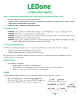
0-10V DIMMABLE WIRING WITH WATTSTOPPER SENSOR
Universal voltage driver and Wattstopper Sensor permits
operation at 120V thru 277V, 50 or 60 Hz. For 0-10V Dimming
with Wattstopper, follow the wiring directions (Fig.11)
1. Connect the black fi xture lead to the LOAD of Wattstopper
Sensor.
2. Connect LINE of Wattstopper Sensor to LINE supply lead.
3. Connect the white fi xture lead and NEUTRAL of
Wattstopper Sensor to the COMMON supply lead.
4. Connect the GROUND wire from fi xture and Wattstopper
Sensor to supply ground. Do NOT connect the GROUND
of the dimming fi xture to the output.
5. Connect the purple fi xture lead to DIM + of
Wattstopper Sensor.
6. Connect the gray fi xture lead to the DIM - of
Wattstopper Sensor lead.
7. Cap the yellow fi xture lead, if present. Do NOT connect
Note: These instructions do not cover all details or variations in equipment nor do they provide for every possible situation during installation, operation or maintenance.
To reduce the risk of electric shock, disconnect both normal and emergency power supplies and converter connector of the emergency ballast before servicing. Do not attempt to service
the emergency ballast. The use of accessory equipment may cause an unsafe condition. Do not use this product for other than intended use. Refer any servicing indicated by these checks
to a Qualifi ed Service Personnel.
Dimming
Driver
LED
LINE
LINE
NEUTRAL
NEUTRAL
GROUND
GRAY (-)
VIOLET (+)
LOAD
LOAD
Occupancy Sensor
5E4
800.879.8585
www.wattstopper.com
r59151 1
OL DA
ENIL
TUEN
teloiv( )
(grey)
18-20 AWG Solid CU Wire Only
230 VAC, 50 Hz
1200W max ballast
FSP-211
DNRG
-MID
DIM+
14-18 AWG Solid CU Wire Only
High/Low PIR
FIG. 11
IVEPARK™ INSTALLATION INSTRUCTIONS
Thank you for buying RAB lighting fi xtures. Our goal is to design the best quality products to get the job done right. We’d like to hear your comments.
Call the Marketing Department at 888-RAB-1000 or email: marketing@rablighting.com
Easy Answers
rablighting.com
Visit our website for product info
Tech Help Line
Call our experts - 888 722-1000
e-mail
Answered promptly - sales@rablighting.com
Free Lighting Layouts
Answered online or by request
© 2018 RAB LIGHTING Inc.
Northvale, New Jersey 07647 USA
IVEPARK 1018
EMERGENCY OPERATION
1. When AC power is applied, the charging indicator light is illumi-
nated, indicating that the battery is being charged.
2. When power fails, the emergency ballast automatically switches
to emergency power (internal battery), operating at reduced
illumination. The emergency ballast supplies max 8W of power
in emergency mode for a minimum of 90 minutes.
3. When AC power is restored, the emergency ballast automatically
returns to charging mode.
EMERGENCY MAINTENANCE
Although no routine maintenance is required to keep the emergency
ballast functional, it should be checked periodically to ensure that it
is working. The following schedule is recommended:
1. Visually inspect the charging indicator light monthly. It should be
illuminated.
2. Test the emergency operation of the fi xture at 30-day intervals for a
minimum of 30 seconds.
3. Conduct a 90-minute discharge test once a year. Fixture would
operate at reduced illumination for a minimum of 90 minutes.
TROUBLESHOOTING
1. Check that the line voltage at the fi xture is correct.
Refer to wiring directions.
2. Be sure the fi xture is grounded properly.
CLEANING & MAINTENANCE
CAUTION: Be sure fi xture temperature is cool enough to touch.
Do not clean or maintain while fi xture is energized.
1. Clean acrylic lens with non-abrasive cleaning solution.
2. Do not open the fi xture to clean the LEDs. Do not touch the LEDs.
ACCESSORIES
IVG-SF - Single Fuse for 120V, 277V, or 347V
IVG-DF - Double Fuse for 208V, 240V, or 480V
IVGYKZ(W) - Yoke mount (Bronze/ White)
IVGWFZ(W) - Flat Wall (Bronze/ White)
IVGPAZ(W) - Universal Pole Adapter (Bronze/ White)
IVG-SPU - 10kV Surge 120V & 277V
IVG-SP3 - 10kV Surge 347V
IVG-SP4 - 10kV Surge 480V
Note: These instructions do not cover all details or variations in equipment nor do they provide for every possible situation during installation, operation or maintenance.
To reduce the risk of electric shock, disconnect both normal and emergency power supplies and converter connector of the emergency ballast before servicing. Do not attempt to service
the emergency ballast. The use of accessory equipment may cause an unsafe condition. Do not use this product for other than intended use. Refer any servicing indicated by these checks
to a Qualifi ed Service Personnel.
Test Switch
FIG. 12
  • Page 1 1
  • Page 2 2
  • Page 3 3
  • Page 4 4
  • Page 5 5
  • Page 6 6

RAB Lighting IVGT5U-30L740WU/WS2 Operating instructions

Type
Operating instructions

Ask a question and I''ll find the answer in the document

Finding information in a document is now easier with AI