Page is loading ...

Homewerks.com
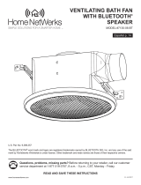
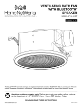
BATH FAN WITH BLUETOOTH®
SPEAKERS, LED LIGHT,
AND NIGHT LIGHT
MODEL 7130-16-BT
Español p. 13
8-2021
Questions, problems, missing parts? Before returning to your retailer, call our customer
service department at 1-877-319-3757, 7:30 a.m. - 4:30 p.m., CST, Monday - Friday.
The BLUETOOTH® word mark and logos are registered trademarks owned by BLUETOOTH SIG, Inc. and any use of the said
mark by Homewerks Worldwide is under license. Other trademark and trade names are those of their respective owners.
U.S. Pat. No. 9,398,357
READ AND SAVE THESE INSTRUCTIONS

2Homewerks.com
TABLE OF CONTENTS
PRODUCT SPECIFICATIONS
Airow: 110 CFM LED light power consumption: 15W
120V, 60Hz LED light brightness: 600 lumens
Duct diameter: 4 in. LED light color (CCT): 4000K Cool White
Sound output: 1.5 Sones Night light color: Blue and amber
Motor power consumption: 28.8 W Weight: 9.5 lbs.
Exhaust fan speed: 920 RPM
Product Specications ........................................................................................................................2
FCC Compliance ................................................................................................................................2
Package Contents ..............................................................................................................................3
Hardware Included .............................................................................................................................3
Safety Information ..............................................................................................................................4
Preparation .........................................................................................................................................4
Installation Instructions .......................................................................................................................6
Pairing Light Switch with Fan .............................................................................................................9
Connecting BLUETOOTH® Device to Speaker ..................................................................................9
Care and Cleaning..............................................................................................................................9
Troubleshooting ................................................................................................................................ 11
Warranty ...........................................................................................................................................12
FCC COMPLIANCE
NOTICE: This equipment has been tested and found to comply with the
limits for a Class B digital device, pursuant to part 15 of the FCC Rules.
These limits are designed to provide reasonable protection against
harmful interference in a residential installation.
This equipment generates, uses, and can radiate radio frequency energy
and, if not installed and used in accordance with the instructions, may
cause harmful interference to radio communications. However, there is
no guarantee that interference will not occur in a particular installation.
If this equipment does cause harmful interference to radio or television
reception, which can be determined by turning the equipment off and on,
the user is encouraged totry to correct the interference by one or more
of the following measures:
– Reorient or relocate the receiving antenna.
– Increase the separation between the equipment and receiver.
– Connect the equipment into an outlet on a circuit different from that
to which the receiver is connected.
– Consult the dealer or an experienced radio/TV technician for help.
Changes or modications made to this equipment not expressly approved
by the party responsible for compliance could void the user's authority
to operate the equipment.

3
Homewerks.com
HARDWARE INCLUDED (not actual size)
AA BB CC
Wood Screw
M4 x 30
Machine Screw
M4 x 12
Machine Screw
M4 x 10
Qty. 8 Qty. 2 Qty. 1
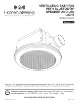
PACKAGE CONTENTS
F
C
E
D
NIGHT LIGHT
PART DESCRIPTION QTY
A Fan Housing 1
BGrille with BLUETOOTH®
Speakers and LED Light 1
C Suspension Bracket 1
D Suspension Bracket 1
PART DESCRIPTION QTY
E Suspension Bracket 1
F Wall Switch 1
A
B

4Homewerks.com
SAFETY INFORMATION
Please read and understand this entire manual before attempting to assemble, operate or install
the product.
• Always disconnect the power supply prior to servicing the
fan, motor or junction box.
• Follow all local building, safety and electrical codes
as well as NEC (National Electrical Code) and OSHA
(Occupational Safety and Health Act).
• Electric Service supply must be 120 volts, 60 hertz.
• This product must properly connect to the grounding
conductor of the supply circuit.
• Do not bend or kink the power wires.
• Do not use this fan with any solid state control device,
such as a remote control, dimmer switch, or certain
timers. Mechanical timers are not solid state devices.
• Do not install in a ceiling with insulation greater than R40.
• Duct work should be installed in a straight line with
minimal bends.
• Duct work size must be the same size as the discharge
and should not be reduced. Reducing the duct size may
increase fan noise.
• This product is not intended for connection to rigid metal
conduit. For use with exible conduit only.
WARNING: To reduce the risk of re, electric shock,
or injury to persons, observe the following:
1. Use this unit in the manner intended by the manufacturer.
If you have any questions, please call customer service.
2. Before servicing or cleaning unit, switch power off at
service panel and lock the service disconnecting means
to prevent power from being switched on accidentally.
When the service disconnecting means cannot be locked,
securely fasten a prominent warning device, such as a
tag, to the service panel.
3. Installation work and electrical wiring must be done by
a qualied person(s) in accordance with all applicable
codes and standards, including re-rated construction.
4. Sufcient air is needed for proper combustion and
exhausting of gases through the ue (chimney) of fuel
burning equipment to prevent backdrafting.Follow the
heating equipment manufacturer´s guideline and safety
standards such as those published by the National Fire
Protection Association (NFPA), and the American Society
for Heating, Refrigeration and Air Conditioning Engineers
(ASHRAE) and local code authorities.
5. When cutting or drilling into the wall or ceiling, do not
damage electrical wiring and other hidden utilities.
6. To reduce risk of re and to properly exhaust air, be sure
to vent air to the outdoors. Do not vent exhaust air into
spaces within walls or ceilings, or into attics, crawl
spaces, or garages.
7. If this unit is to be installed over a tub or shower, it must
be marked as appropriate for the application and be
connected to a GFCI (Ground Fault Circuit Interrupter) –
protected branch circuit.
8. This ventilation fan is intended to be installed at least 3.28
ft. (1 m) from the showerhead when installing over
a bathtub or shower. Installation within a shower stall is
not recommended for this unit, unless the 3.28 ft.
(1 m) distance can be met.
CAUTION
• For general ventilating use only. Do not use to
exhaust hazardous or explosive materials and
vapors.
• Not for use in kitchens.
• To reduce the risk of injury to persons, install
the fan at least 7 feet (2.1m) above the oor.
• To reduce risk of re and to properly exhaust air,
be sure to vent air to the outdoors. Do not vent
exhaust air into spaces within walls or ceilings,
or into attics, crawl spaces, or garages.
CAUTION: Installation of this unit requires the power to be OFF until installation is complete. If you encounter issues with the
unit not powering up, please review the troubleshooting section of the instruction manual.
If you require additional assistance, please call 1-877-319-3757, 7:30 a.m. - 4:30 p.m., CST, Monday - Friday. DO NOT
RETURN TO STORE.
PREPARATION
Before beginning assembly of product, make sure all parts are present. Compare parts with package
contents list and hardware contents. If any part is missing or damaged, do not attempt to assemble, install or
operate the product. Contact customer service for replacement parts at 1-877-319-3757, 7:30 a.m. - 4:30
p.m., CST, Monday - Friday.
Tools Required for Assembly (not included): Hammer, Flathead Screwdriver, Wire Connectors, Nails, Duct Tape,
Phillips Head Screwdriver, and Utility Knife or Drywall Saw.
Helpful Tools (not included): Electric Drill, Drill Bits

5
Homewerks.com
PREPARATION (continued)
ATTENTION:
The switch included with this ventilation
fan requires a dedicated neutral wire
connection. If a neutral line is not
present, one must be run by a
qualied electrician.
NOTE: This switch is intended to only
operate independently with this bath
fan. Connections to other electrical
xtures is prohibited and could cause
electrical issues.
If you require assistance, please call
1-877-319-3757 before attempting
switch installation.
WARNING: RISK OF ELECTRIC SHOCK! Ensure the electricity to the wires you are working on is shut
off. Either remove the fuse or turn off the circuit breaker before removing the existing bath fan or
installing the new one.
Before removing your current ventilation fan, verify the wall switch box has the required wires
necessary for this installation. These supply wires are power (black) and neutral (white), as shown in
the wiring diagram below. If you do not see both of these wires, consult a licensed electrician.
Check area above installation location to be sure that wiring can run to the planned location and that duct work
can be run and the area is sufcient for proper ventilation.
Inspect duct work and wiring before proceeding with installation.
Before installation, provide inspection and future maintenance access at a location that will not interfere with
installation work.
You may need the help of a second person to install this fan; one person on the attic side and one on the room side.
Installation may vary depending on how the previous bath fan was installed. Supplies necessary for the installation
of your bath fan are not all included; however, most are available at your local home improvement or hardware
store.
DIMENSIONS
Ceiling
Opening (L)
Ceiling
Opening (W)
Ceiling
Opening (H)
Housing
Dimension (L)
Housing
Dimension (W)
Housing
Dimension (H)
9-3/8 in. 9-3/8 in. 7-1/2 in. 9-1/4 in. 9-1/4 in. 7-3/8 in.
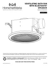
WIRING
All wiring must be connected for full functionality. Do not use metal wall plate with switch.
NIGHT LIGHT
LIGHT
FAN
MUSIC
House neutral/white
Power/black
Ground wire/green
Switch
connection/black
Fan neutral/white
Switch/red
Fan
AC120V/60Hz
Green
Red
White
Black

6
INSTALLATION INSTRUCTIONS
BEFORE INSTALLATION
WARNING: RISK OF ELECTRIC SHOCK! Ensure the electricity
to the wires you are working on is shut off. Either remove the
fuse or turn off the circuit breaker before removing the existing
bath fan or installing the new one.
1. Remove existing fan.
If you are not replacing an existing fan, skip to step 3.
2. Measure the opening to ensure it is large enough to
accommodate the 9-1/4 in. x 9-1/4 in. dimensions of the new
fan housing (A).
3. If this fan is not replacing an old fan be sure to cut a
9-3/8 in. x 9-3/8 in. opening for the fan housing (A).
For spacing of 15 in. to 23-1/2 in. between ceiling joists:
4. Insert suspension bracket (C) into the tabs on the duct side
of the fan housing (A). Insert suspension bracket (D) into the
tabs on the opposite side of the fan housing (A) and then slide
suspension bracket (E) into suspension bracket (D).
1
2
3
9-3/8"
9-3/8"
4C
D
E
Homewerks.com

7
Homewerks.com
INSTALLATION INSTRUCTIONS (continued)
5
6
5. Position the fan housing (A) so the bottom edge of the fan
housing (A) is ush with the ceiling board. Do not ush mount the
fan housing (A) to the bottom of the joist.
6. Attach the end of each of the suspension brackets (C, D, E) to
the ceiling joists using wood screws (AA).
7. Secure suspension bracket (C) to the fan housing (A) using a
machine screw (CC) and the suspension brackets (D,E) to the
fan housing (A) using machine screws (BB).
8. Remove the wiring box cover from the fan housing (A). Pull the
house wires through the hole in the wiring box cover. Using the
quick connectors, connect the house wiring to the wall switch
(F) and fan housing (A). 14 AWG is the smallest conductor that
should be used for branch circuit wiring. Please refer to the
wiring diagram on page 5 to ensure proper wire connections are
made. Carefully push the wire connections into the wiring box
and reattach the wiring box cover.
NOTE: Do not use metal wall plate with the wall switch (F), as it
may cause interference with the fan operation.
CAUTION: The switch included with this ventilation fan requires
a neutral wire connection. If a neutral line is not present, one
must be run by a qualied electrician. If you require assistance,
please call 1-877-319-3757 before attempting switch installation.
CAUTION: This switch is intended to only operate with this bath
fan. Connections to other electrical xtures are prohibited and
could cause electrical issues.
1 2
A
7
E
A
C
CC
D
DAA
AA
Wiring box cover
Quick connector
8
A

8Homewerks.com
INSTALLATION INSTRUCTIONS (continued)
9. Connect a 4 in. circular duct to the fan housing (A), securing it
with duct tape or a clamp. Vent the duct to the outside.
Turn on power source. Test the fan.
10. Join the connectors for the BLUETOOTH® speaker and LED
light from the fan housing (A) to the grille (B). After push-
ing the two gray connectors rmly together, twist the plastic
nut to secure the connection. Repeat the same step for the
small black connectors. The grille (B) must be connected
BEFORE turning on power to the fan.
11. Attach grille (B) by pinching the mounting springs and
inserting them into narrow rectangular slots in the fan
housing (A).
Turn on power source. Test the unit.
11
10
9
A
Gray
connectors
A
B
Black
connectors
Housing slots
Mounting
springs
B
A

9
Homewerks.com
This is a one-time pairing to be done after turning on the power source.
1. Turn switch to ON. The white LED light on the fan should be on.
2. Cycle the switch ON & OFF multiple times, pausing one second between each cycle, until the LED night
light on the fan is ashing.
3. While the LED night light is ashing, press LIGHT.
4. The LED night light will stop ashing and appear as solid blue. The switch is now paired with fan and all four
setting buttons on the switch should now be functional. NOTE: If the LED night light stops ashing and the
white LED light is on the pairing was unsuccessful, repeat steps 2-4.
Any combination of settings can be achieved by individually pressing each setting button, except LED light and
night light. For example, pressing LIGHT and FAN will turn on the exhaust fan and LED light. Pressing LIGHT
and MUSIC will turn on LED light and Bluetooth speaker.
To cycle through the blue and amber night light colors, press the night light button repeatedly.
NOTE: Should you ever lose pairing between the switch and fan, repeat steps 2-4.
If installing multiple units or you are having an issue pairing the switch to the fan:
A. Make sure all toggle switches are in the OFF position.
B. Cycle the rst switch ON and OFF multiple times, pausing one second between each cycle, until the LED night
light on the fan is ashing.
C. While the LED night light is ashing, press MUSIC. The LED night light will stop ashing. Follow steps 1 - 4 above.
D. If connecting another unit, turn the fan off and repeat steps A-C for any remaining fans.
CONNECTING YOUR BLUETOOTH® DEVICE TO THE SPEAKER
1. To play your personal music les, you need a wireless BLUETOOTH® device.
2. Set your device to a midrange volume before connecting to the speaker.
3. Follow the instructions that came with your BLUETOOTH® device to make it discoverable or to set it
to search for other BLUETOOTH® accessories. This may involve entering a passkey or PIN (Personal
Identication Number).
4. From the Home screen, choose Settings > BLUETOOTH®, to search for the speaker. NOTE: While your
device can maintain multiple pairing records, it can only connect to one accessory at a time. This prevents
your device from sending your data to the wrong BLUETOOTH® accessory.
5. Choose the Homewerks™ speaker, and then enter a passkey or PIN (0000) if prompted.
6. When pairing is complete, use the BLUETOOTH® speaker to play audio from your device.
7. Optimal volume setting for the BLUETOOTH® speaker is 70% or lower. Settings higher than 70%
may cause sound distortion.
PAIRING LIGHT SWITCH WITH FAN
CARE AND CLEANING
CAUTION: Before attempting to clean the xture, disconnect the power to the xture by turning
the breaker off or removing the fuse from the fuse box.
• See safety information before proceeding. Routine maintenance should be done at least once a year.
• Never use solvents, thinner or harsh chemicals for cleaning the fan.
• Do not allow water to enter the motor.
• Do not immerse metal parts in water.
• Do not immerse resin parts in water over 140 degrees Fahrenheit.
• Do not immerse BLUETOOTH® speaker in water

10 Homewerks.com
WARNING: RISK OF ELECTRIC SHOCK! Ensure the electricity is
shut off. Either remove the fuse or turn off the circuit breaker before
cleaning.
1. Squeeze the mounting springs and pull the grille (B) down from
the fan housing (A). Disconnect the connectors to remove the
grille (B) from the fan housing (A). Remember to twist the ends
of the small gray and black connectors to unlock them before
pulling them apart. Wipe grille (B) with a damp cloth.
CAUTION: Do not immerse speakers in water.
2. Remove dust and dirt from the fan housing (A) with a
vacuum cleaner.
3. Wipe the fan housing (A) with a damp cloth and wipe dry.
4. Join the connectors for the BLUETOOTH® speaker and LED
light from the fan housing (A) to the grille (B). After pushing
the two gray connectors rmly together, twist the plastic nut
to secure the connection. Repeat the same step for the small
black connectors. The grille (B) must be connected BEFORE
turning on power to the fan.
4
Gray
connectors
A
B
Black
connectors
Mounting
springs
1
Gray
connectors
A
B
Mounting
springs Black
connectors
2
A
3
A
CARE AND CLEANING (continued)

11
Homewerks.com
CARE AND CLEANING (continued)
5
5. Attach grille (B) by pinching the mounting springs and inserting
them into the narrow rectangular slots in the fan housing (A).
Turn on power source. Test the unit Housing slots
A
B
Mounting
springs
TROUBLESHOOTING
PROBLEM POSSIBLE CAUSE SOLUTION
The fan seems louder than it
should.
The CFM is too great for the space. Be sure the CFM rating on the fan matches the
square footage of your room.
The damper is damaged or not working properly. Check the damper to ensure it is opening and closing
properly. If the damper has become damaged, please
call Customer Service.
The bend in the duct is too close to the fan discharge.Be sure you do not have any sharp bends in the duct
within 18 in. of the fan discharge.
The fan discharge is reduced to t a smaller duct. Use the recommended size ducting to reduce fan
noise.
The fan body is not attached securely. Be sure the fan is securely attached to the ceiling
joists.
The fan is not clearing
humidity from the room.
There is insufcient airow intake in the room. Be sure a door or window is slightly ajar or open to
allow airow. The fan is not able to draw air out of the
room without enough airow.
There is insufcient CFM.
NOTE: Using a tissue is not the correct method for
determining if the fan is operating properly. If the fan
clears steam from the room within approximately 15
minutes of completing your shower, then the fan is
operating properly.
Be sure the CFM rating of the fan matches the
square footage of your room.
Bluetooth device will not pair
with the fan. Another device is already paired. Make sure BLUETOOTH® signal is turned off on other
devices.
Switch will not power up. There is a wiring issue at the switch, or the power is
not turned on at the fuse box or circuit breaker. Check the wiring diagram on Page 5 and conrm
wiring is correct. Verify the power is turned on.
Switch has power, but the
fan does not.
The grille is not receiving a signal from the switch.
Turn off power. Verify the three connectors from the fan
housing (A) to the grille (B) are connected correctly, then
test. If necessary, disconnect the grille for 5 seconds,
then reconnect the grille and test. Repeat as necessary.
Neutral wire connection from the switch to the fan is
not engaging.
Turn off power. Conrm the house neutral wire is
connected to the switch neutral wire and fan neutral
wire. The switch included with this ventilation fan
requires a dedicated neutral wire connection. If a
neutral line is not present, one must be run by a
qualied electrician.

12 Homewerks.com
FAN – LIMITED 3-YEAR WARRANTY
BLUETOOTH® SPEAKER – LIMITED 1-YEAR WARRANTY
If the fan fails due to a defect in materials or workmanship at any time during the rst THREE years of ownership, the manufacturer will
replace it free of charge, postage-paid at their option. This warranty does not cover products that have been abused, altered, damaged,
misused, cut or worn. This warranty does not cover use in commercial applications. Use only manufacturer-supplied genuine warranty
repair replacement parts to repair this fan. Use of non-genuine repair parts will void your warranty. The manufacturer DISCLAIMS all
other implied or express warranties including all warranties of merchantability and/or tness for a particular purpose. As some states do
not allow exclusions or limitations on an implied warranty, the above exclusions and limitations may not apply. This warranty gives
you specic legal rights, and you may have other rights that vary from state to state.
This warranty is limited to the replacement of defective parts only. Labor charges and/or damage incurred during installation, repair,
replacement as well as incidental and consequential damages connected with the above are excluded. Any damage to this product
as a result of neglect, misuse, accident, improper installation or use other than the purpose SHALL VOID THIS WARRANTY.
Shipping costs for return product as part of a claim on the warranty must be paid for by the customer.
Inquiries regarding warranty claims can be directed to 1-877-319-3757, 7:30 a.m. - 4:30 p.m., Monday - Friday.
If the BLUETOOTH® speaker fails due to a defect in materials or workmanship at any time during the rst year of ownership, the
manufacturer will replace it free of charge, postage-paid at their option. This warranty does not cover products that have been abused,
altered, damaged, misused, cut or worn. This warranty does not cover use in commercial applications. Use only manufacturer-supplied
genuine warranty repair replacement parts to repair this fan. Use of non-genuine repair parts will void your warranty. The manufacturer
DISCLAIMS all other implied or express warranties including all warranties of merchantability and/or tness for a particular purpose. As
some states do not allow exclusions or limitations on an implied warranty, the above exclusions and limitations may not apply. This
warranty gives you specic legal rights, and you may have other rights that vary from state to state.
This warranty is limited to the replacement of defective parts only. Labor charges and/or damage incurred during installation, repair,
replacement as well as incidental and consequential damages connected with the above are excluded. Any damage to this product
as a result of neglect, misuse, accident, improper installation or use other than the purpose SHALL VOID THIS WARRANTY.
Shipping costs for return product as part of a claim on the warranty must be paid for by the customer.
Inquiries regarding warranty claims can be directed to 1-877-319-3757, 7:30 a.m. - 4:30 p.m., CST, Monday - Friday.

13
Homewerks.com
¿Tiene preguntas, problemas, o faltan piezas? Antes de regresar a la tienda, llame al
Servicio al Cliente, 1-877-319-3757, de lunes a viernes de 7:30 a.m. a 4:30 p.m.,
hora estándar central.
VENTILADOR DE BAÑO
CON ALTAVOZ BLUETOOTH®,
LUZ LED Y LUZ NOCTURNA
MODELO 7130-16-BT
La palabra y logotipos de Bluetooth® son propiedad de Bluetooth SIG, Inc., y cualquier uso de estas marcas por parte de
Homewerks Worldwide se efectúa bajo licencia. Otras marcas y nombres comerciales son los de sus respectivos dueños.
CONSERVE ESTE MANUAL PARA USO FUTURO
Número de patente de EE.UU. 9,398,357

14 Homewerks.com
TABLA DE CONTENIDO
ESPECIFICACIONES DEL PRODUCTO
Flujo de aire: 110 CFM Consumo eléctrico del LED: 15 W
120 V, 60 Hz Brillo del LED: 600 lumenes
Diámetro del conducto: 4 pulg. Color de luz LED (CCT): 4000K Blanco frío
Volumen sonoro: 1,5 sones Color de la luz nocturna: Azul y ámbar
Consumo eléctrico motor: 28.8 W Peso: 4,3 kg
Velocidad del extractor: 920 RPM
Especicaciones del producto .......................................................................................................... 14
Cumplimiento de la normas FCC .....................................................................................................14
Contenido del paquete .....................................................................................................................15
Materiales incluidos ..........................................................................................................................15
Información sobre seguridad ............................................................................................................16
Preparación ......................................................................................................................................16
Instrucciones de installación.............................................................................................................18
Emparejar el interruptor de la luz con el ventilador ..........................................................................21
Conexión un dispositivo Bluetooth® al altavoz ..................................................................................21
Cuidado y limpieza ...........................................................................................................................21
Solución de problemas .....................................................................................................................23
Garantía............................................................................................................................................24
CUMPLIMIENTO DE LA NORMAS FCC
AVISO: este equipo ha sido sometido a prueba y se halló que cumple con
los límites establecidos para la clase B de dispositivos digitales,
conforme a la Parte 15 de las Normas de FCC. Estos límites se establ-
ecen para brindar protección razonable contra interferencia dañina en
una instalación residencial.
Este equipo genera, utiliza y puede irradiar energía de frecuencias de
radio y, si no se instala conforme a las instrucciones, puede provocar
interferencia dañina a las comunicaciones de radio. A pesar de esto, no
existe garantía de que la interferencia no se produzca en una instalación
en particular.
Si este equipo produce interferencia dañina a la recepción de radio o
televisión, lo que puede determinarse encendiendo y apagando el
equipo, se insta al usuario a intentar corregir la interferencia mediante
uno de los siguientes métodos:
– Cambie la orientación o ubicación de la antena receptora.
– Aumente la separación entre el equipo y el receptor.
– Conecte el equipo en un enchufe que esté en un circuito diferente al
cual está conectado el receptor.
– Consulte con el representante o con un técnico perimentado en radio y
relecisión para solicitar asistencia.
Los cambios o modicaciones que on estén expresamente aprobados
por la parte responsable del cumplimiento anulan la autoridad del usuario
de operar el equipo.

15
Homewerks.com
PIEZA DESCRIPCIÓN CANTIDAD
A Carcasa del ventilador 1
BRejilla con altavoz
BLUETOOTH® y luz LED 1
CSoporte de suspensión 1
DSoporte de suspensión 1
PIEZA DESCRIPCIÓN CANTIDAD
ESoporte de suspensión 1
F Interuptor de pared 1
MATERIALES INCLUIDOS (no se ilustran en tamaño real)
AA BB CC
Tornillo para
madera Tornillo para
metales Tornillo para
metales
M4 x 30mm M4 x 12mm M4 x 10mm
Cantidad 8 Cantidad 2 Cantidad 1
CONTENIDO DEL PAQUETE
A
F
B
C
E
D
NIGHT LIGHT

16 Homewerks.com
INFORMACIÓN SOBRE SEGURIDAD
Por favor, lea y comprenda este manual en su totalidad antes de intentar de ensamblar, operar
o instalar el producto.
• Siempre desconecte la fuente de alimentación antes de
darle servicio al ventilador, motor o caja eléctrica.
• Siga todos los codigos locales de construccion,
de seguridad y electricos asi como el NEC (Codigo
Electrico Nacional) y OSHA (Ley de Salud y
Seguridad Ocupacional).
• El suministro del servicio electrico debe ser de
120 voltios, 60 hertz.
• Este producto debe estar correctamente conectado al
conductor de conexion a tierra del circuito de
alimentacion.
• No doble ni retuerza los cables de energia.
• No use este ventilador con ningún dispositivo de control
de estado sólido, como un control remoto, interruptor de
atenuación o ciertos temporizadores. Los temporizadores
mecánicos no son dispositivos de estado sólido.
• No instale en un techo con aislamiento mayor de R40.
• Conductos se deben instalar en una línea recta con
curvas mínimas.
• El tamaño del conducto debe ser de mismo tamaño que
la descarga y no debe ser reducido. Reducir el tamaño
del conducto puede aumentar el ruido del ventilador.
• Este producto no está diseñado para conectarse a
conductos metálicos rígidos. Solo para uso con
conductos exibles.
ADVERTENCIA: para reducir el riesgo de incendio,
choque eléctrico o lesiones a las personas, respete
lo siguiente:
1. Use esta unidad en la manera prevista por el fabricante.
Si tiene alguna pregunta, por favor llame al Servicio al
Cliente.
2. Antes de dar servicio o limpiar esta unidad apague la
fuente de alimentación en el panel y bloquélo para evitar
que se encendia la alimentación accidentalmente. Si no
puede bloquear el panel, marque claramente el panel con
una etiqueta de advertencia para evitar que se encienda
la alimentación.
3. El trabajo de instalación y el cableado eléctrico debe ser
hecho por una persona calicada, de acuerdo con todos
los códigos y normas aplicables, incluyendo la
construcción con clasicación ignífuga.
4. Se necesita suciente aire para una combustión
apropiada y el escape de los gases a través del conducto
(chimenea) del equipo que quema combustible para
evitar contratiraje. Siga las guias del fabricante de equipo
de calefacción y las normas de seguridad como las
publicadas de la Asociación Nacional de Protección
contra Incendios (NFPA), y de la Sociedad
Estadounidense de Ingenieros en Calefacción,
Refrigeración y Aire Acondicionado (ASHRAE), y las
autoridades de código local.
5. Cuando corte o perfore en la pared o techo, no dañe el
cableado eléctrico u otros servicios ocultos.
6. Para reducir el riesgo de incendio y extraer el aire de
manera adecuada, asegúrese de ventilar el aire hacia el
exterior. No extraiga el aire en espacios dentro de
paredes o techos, o en áticos, entrepisos o garajes.
7. Si esta unidad se va a instalar sobre una bañera o ducha,
se debe marcar según sea apropiado para la aplicación y
conectarse a un circuito de derivación protegido GFCI
(Interruptor de circuito de falla a tierra).
8. Este ventilador-extractor está diseñado para instalarse
por lo menos a 1 m del cabezal de la ducha cuando
se instala sobre una bañera o ducha. La instalación
dentro de una cabina de ducha no se recomienda a
menos que se pueda alcanzar la distancia de 1 m.
PRECAUCIÓN
• Para uso de ventilación general solamente. No
lo use para desalojar materiales y vapores
peligrosos o explosivos.
• No debe usarse en cocina.
• Para reducir el riesgo de lesiones a las personas,
instale el ventilador al menos a 7 pies (2.1m)
sobre el piso.
• Para reducir el riesgo de incendio y extraer el
aire de manera adecuada, asegúrese de ventilar
el aire hacia el exterior. No extraiga el aire en
espacios dentro de paredes o techos, o en
áticos, entrepisos o garajes.
PRECAUCIÓN: la instalación de esta unidad requiere que la energía esté apagada hasta que se complete la
instalación. Si encuentra problemas con la unidad que no se enciende, revise la sección de solución de problemas del
manual de instrucciones.
Si necesita asistencia adicional, llame al 1-877-319-3757, de 7:30 a.m. a 4:30 p.m., HCE, de lunes a viernes. NO REGRESE
A LA TIENDA.
PREPARACIÓN
Antes de comenzar a ensamblar este producto, asegurese de que todas las piezas esten presentes. Compare las piezas con
la lista de contenido del paquete y herraje incluido. Si hace falta alguna pieza o se encuentra danada, no intente ensamblar el
producto. Pongase en contacto con el Servicio al Cliente para piezas de repuesto 1-877-319-3757, de 7:30 a. m. a
4:30 p. m., hora central estándar, de lunes a viernes.

17
Homewerks.com
Herramientas necesarias para armar (no incluidas): martillo, destornillador de cabeza plana, conectores de cables,
clavos, cinta adhesiva, destornillador de estrella, y cuchillo multiuso o sierra para paneles de yeso.
Herramientas útiles (no incluidas): taladro eléctrico, brocas de taladro.
ADVERTENCIA: ¡RIESGO DE DESCARGA ELECTRICA! Asegurese de cortar el suministro electrico en los cables
con los que trabajara. Extraiga los fusibles o apague el cortacircuitos antes de quitar el ventilador de baño
existente o instalar uno nuevo.
Antes de quitar su ventilador actual, verique que su caja de interruptores en la pared tenga los cables de suministro
necesarios para esta instalación. Estos cables de alimentación (negro) y neutro (blanco) como se muestra en el
diagrama de cableado a continuación. Si no ve estos dos cables, consulte a un electricista autorizado.
Compruebe el área sobre la ubicación de instalación para asegurarse de que el cableado puede correr
a la ubicación prevista y que los conductos se puede correr y el área es suciente para una ventilación
adecuada.
Inspeccione los conductos y el cableado antes de proceder con la instalación.
Antes de la instalación, proporcione acceso para la inspección y el mantenimiento en un lugar que no
interera con el trabajo de instalación.
Es posible que necesite la ayuda de una segunda persona para instalar este ventilador; una en el lado
del ático y otra en el lado de la habitación.
La instalacion puede variar dependiendo de cómo se instaló el ventilador anterior. Los suministros
necesarios para la instalación de su ventilador de baño no están todos incluidos; sin embargo, la may-
oría están disponibles en su tienda de artículos del hogar o ferretería local.
DIMENSIÓNES
Aperturo
de techo (La)
Aperturo
de techo (An)
Aperturo
de techo (Al)
Dimensiones
de caja (La)
Dimensiones
de caja (An)
Dimensiones
de caja (Al)
23,9 cm 23,9 cm 19,1 cm 23,5 cm 23,5 cm 18,73 cm
CABLEADO
Todo el cableado debe estar conectada a la funcionalidad completa. No use una placa de pared de
metal con el interruptor.
PREPARACIÓN (continuada)
ATENCIÓN
El interruptor incluido con este
ventilador requiere una conexión
de cable neutro dedicado. Si no
hay una cable neutro, uno debe
ser ejecutado por un electricista
calicado.
NOTA: este interruptor está
diseñado para funcionar solo de
manera independiente con este
ventilador de baño. Las conexines
a otros accesorios eléctricos
están prohibidas y podrían causar
problemas eléctricos.
Si necesita ayuda, por favor llame
al 1-877-319-3757 antes de
intentar instalar el interruptor.
Conexión a tierra /Cables verdes
Potencia/negro
Interruptor /rojo
Conector,
interruptor/negro
Vivienda neutro/blanco
AC120V/60Hz

18 Homewerks.com
INSTRUCCIONES DE INSTALACIÓN
PREVIO A LA INSTALACIÓN
ADVERTENCIA: ¡RIESGO DE DESCARGA ELECTRICA!
Asegurese de cortar el suministro electrico en los cables con los
que trabajara. Extraiga los fusibles o apague el cortacircuitos
antes de quitar el ventilador de baño existente o instalar uno
nuevo.
1. Retire el ventilador existente.
Si no está reemplazando un ventilador existente, vaya al
paso 3.
2. Mida la abertura para asegurarse de que sea lo suciente-
mente grande para acomodar las dimensiones de 23,5 cm x
23,5 cm de la carcasa del nuevo ventilador (A).
3. Si este ventilador no reemplaza a uno viejo, asegúrese de
cortar una abertura de 23,9 cm x 23,9 cm para la carcasa del
ventilador (A).
Instalación con espacio de 38,1 cm a 59,69 cm entre las
vigas del techo:
4. Inserte el soporte de suspensión (C) en las pestañas en el lado
conducto de la carcasa del ventilador (A). Inserte el soporte de
suspensión (D) en las pestañas en el lado opuesto de la car-
casa del ventilador (A) y luego deslice el soporte de suspensión
(E) en el soporte de suspensión (D).
4C
D
E
3
23,9 cm
23,9 cm
2
1

19
Homewerks.com
INSTRUCCIONES DE INSTALACIÓN (continuadas)
5. Coloque la carcasa del ventilador (A) de modo que el borde
inferior de la carcasa del ventilador (A) quede al ras con la
placa del techo. No monte al ras la carcasa del ventilador (A)
en la viga.
6. Fije el extremo de cada uno de los soportes de suspensión
(C, D, E) a las vigas del techo con tornillos para madera (AA).
7. Fije el soporte de suspensión (C) a la carcasa del ventilador (A)
con un tornillo para metales (CC) y los soportes de
suspensión (D, E) a la carcasa del ventilador (A) con tornillos
para metales (BB).
7
E
A
C
CC
8. Retire la cubierta de la caja eléctrica de la carcasa del ventilador (A).
Tire de los cables de la casa a través de la tapa la caja eléctrica.
Usando los conectores rápidos, conecte el cableado de la casa al
interruptor de pared LED (F) y la carcasa del ventilador (A). 14 AWG
es el conductor más pequeño que debe usarse para el cableado del
circuito derivado. Consulte el diagrama de cableado en la página
16 para asegurarse de que se están realizando las conexiones de
cables correctas. Empuje con cuidado las conexiones de cables en la
caja eléctrica y vuelva a colocar la tapa de la caja eléctrica.
NOTA: no utilice una placa de pared de metal con el interruptor (F), ya
que puede causar interferencias en el funcionamiento del ventilador.
PRECAUCIÓN: el interruptor incluido con este ventilador requiere
una conexión de cable neutro. Si no hay un cable neutro, uno debe
ser ejecutado por un electricista calicado. Si necesita ayuda, por
favor llame al 1-877-319-3757 antes de intentar instalar el interruptor.
PRECAUCIÓN: este interruptor está diseñado para funcionar solo
con este ventilador de baño. Las conexiones a otros accesorios eléc-
tricos están prohibidas y podrían causar problemas eléctricos.
Cubierta de la caja eléctrica
Conector rapido
A
8
5
1 2
6
D
DAA
AA
A

20 Homewerks.com
9. Conecte un conducto circular de 4 pulg y ventile hacia el fuera.
Asegure con cinta adhesiva o abrazadera.
Encienda la fuente de energía. Pruebe el ventilador.
10. Une los conectores para el altavoz BLUETOOTH® y la luz
LED de la carcasa del ventilador (A) a la rejilla (B). Después
de presionar rmemente los dos conectores grises, gire la
tuerca plástica para asegurar la conexión. Repita el mismo
paso para los pequeños conectores negros. La rejilla (B)
debe estar conectada ANTES de encender el ventilador.
11. Coloque la rejilla pellizcando resortes de montaje y se
insertan en ranuras rectangulares estrechas en la carcasa
del ventilador (A).
Encienda la fuente de energía. Pruebe el ventilador.
11
Ranuras en
la caja
Resortas de
montaje
B
A
INSTRUCCIONES DE INSTALACIÓN (continuadas)
10
Conectores
grises
A
B
Conectores
negros
Resortas de
montaje
9
A
/