Page is loading ...

Questions, problems, missing parts? Before returning to your retailer, call our customer
service department at 1-877-319-3757, 7:30 a.m. - 4:30 p.m., CST, Monday - Friday.
VENTILATION
FAN WITH LIGHT
MODEL #7117-02-BN
Español p. 11
ATTACH YOUR RECEIPT HERE
Serial Number
_______________
Purchase Date
______________
READ AND SAVE THESE INSTRUCTIONS
04-05-19

2
TABLE OF CONTENTS
SPECIFICATIONS
PRODUCT SPECIFICATIONS LIGHT SPECIFICATIONS
Airow: 80 CFM 3000K Dimmable LED
Sound output: 1.1 Sones 80 CRI
120 V, 60 Hz 16 Watt
Duct diameter: 4 in. 30,000 hours life
AC Motor
Power consumption: 28 Watt
Specications .....................................................................................................................................2
Package Contents ..............................................................................................................................3
Safety Information ..............................................................................................................................3
Preparation .........................................................................................................................................4
New Construction Assembly Instructions ...........................................................................................5
Existing Construction Assembly Instructions ...................................................................................... 7
Care and Maintenance .....................................................................................................................10
Troubleshooting ................................................................................................................................ 10
Warranty ...........................................................................................................................................10
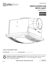
TYPICAL INSTALLATION

3
PACKAGE CONTENTS
PART DESCRIPTION QUANTITY
A Fan housing 1
B Grille and light 1
PART DESCRIPTION QUANTITY
C Duct connector 1
SAFETY INFORMATION
READ AND SAVE THESE INSTRUCTIONS
Please read and understand this entire manual before attempting to assemble, operate or install
the product.
1. Always disconnect the power supply prior to servicing the fan, motor or junction box.
2. Installation work must be carried out by a qualied person(s) in accordance to all local and
safety codes including the rules for re-rated construction.
3. Follow all local building, safety and electrical codes, as well as NEC (National Electrical Code)
and OSHA (Occupational Safety and Health Act).
4. Electric service supply must be 120 volts, 60 hertz.
5. This unit must be properly grounded.
6. Do not bend or kink the power wires.
7. Exercise care to not damage existing wiring when cutting or drilling into walls or ceilings.
HARDWARE CONTENTS (not shown actual size)
AA
Long Wood
Screw
Qty. 6
A
B
C

4
SAFETY INFORMATION
8. Sufcient air supply is required for proper combustion and the exhaustion of gases through
the chimney (ue) of fuel burning equipment to prevent back-drafting. See the standards of
NFPA (National Fire Protection Association) and ASHRAE (American Society for Heating
Refrigeration and Air Conditioning Engineers) and the local building code authorities.
9. Do not use this fan with any solid state control device, such as a remote control, dimmer switch,
or certain timers. Mechanical timers are not solid state devices.
10. This ventilation fan is approved for use over a bathtub or shower when installed in a GFCI
protected circuit. Do not use fans over a bathtub or shower that are not approved for that
application and marked accordingly.
11. Do not install in a cooking area.
12. Do not use to exhaust hazardous or explosive vapors.
13. Fans should always be vented to the exterior and in compliance with local codes.
14. Do not install in a ceiling with insulation greater than R50.
15. Duct work should be installed in a straight line with minimal bends.
16. Duct work size must be the same size as the discharge and should not be reduced. Reducing
the duct size may increase fan noise.
17. Prior to servicing or cleaning this unit, shut off power supply at the panel and lock to
prevent the power from being turned on. If the panel cannot be locked, clearly mark
the panel with a warning tag to prevent the power from being turned on.
18. Use this unit in the manner intended by the manufacturer. If you have any questions, please
call customer service.
PREPARATION
Before beginning assembly of product, make sure all parts are present. Compare parts with package
contents list and hardware contents. If any part is missing or damaged, do not attempt to assemble
the product.
Estimated Assembly Time: 30 minutes
Tools Required for Assembly (not included): Hammer, Flathead Screwdriver, Wood Screws, Duct Tape,
Phillips Screwdriver, Utility Knife
Helpful Tools (not included): Electric Drill, Drill Bits
WARNING: Turn off electricity at breaker box before beginning installation.
Carefully remove unit from carton.
Check area above installation location to be sure that wiring can run to the planned location and that
duct work can be run and the area is sufcient for proper ventilation.
Inspect duct work and wiring before proceeding with installation.
Before installation, provide inspection and future maintenance access at a location that will not interfere
with installation work.
You may need the help of a second person to install this fan: one person on the attic side and one on
the room side.
Note: Installations may vary depending on how the previous bath fan was installed. Supplies necessary
for the installation of your bath fan are not all included; however, most are available at your local
home improvement or hardware store.

5
DIMENSION REQUIREMENTS
Ceiling
Opening (L)
Ceiling
Opening (W)
Ceiling
Opening (H)
7-1/2 in. 7-1/4 in. 5-3/4 in.
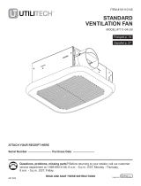
WIRING DIAGRAM
QUICK CONNECTOR INSTRUCTIONS
To be sold only with installation instructions.
WARNING: Wiring must comply with all appliable electrical
codes. Turn OFF power before removing or installing connectors.
WARNING: COPPER TO COPPER ONLY. Do not use aluminum wire.
CAUTION: Accessory part (quick connector) should meet
installation instructions below.
NOTE: The connector is reusable on solid wires of the same wire gage
or smaller. Do not reuse the connector on stranded wires.
NOTE: Important wire information. Maximum temperature rating 221˚F
(105˚C). 600 volts maximum for building wire and 1,000 volts maximum for
building wire and 1,000 volts maximum in signs and lighting xtures.
The acceptable wire range includes: Solid: 12-18 AWG.
• Strip wires 3/8 in. - 1/2 in.
• Grip the wire firmly and push the
stripped end of the wire into the
open port of the connector.
Use only one connector
per port.
• Verify the stripped end of the
wires is fully inserted to the
back of the connector.
Quick
connect
House
wires
Product
wires
NEW CONSTRUCTION INSTALLATION INSTRUCTIONS
Review all safety precautions. Make sure electricity
at the breaker box is turned off before beginning
installation.
1. Cut an opening that measures 7.5 in. x 7.25 in.
2. Attach the duct connetor to the fan housing.
7
.2
5
"
7.5"
1
2

6
Quick
connector
House
wires
Product
wires
NEW CONSTRUCTION INSTALLATION INSTRUCTIONS
3. Place the fan housing next to a ceiling joist. The
fan housing should be level and perpendicular to
the joist.
4. Mount the fan housing to the ceiling joist using the
wood screws (included) where indicated.
5. Remove wiring box cover from fan housing with
Phillips screwdriver (not included).
6. Pull the house wires through the wire box cover hole.
Using a quick connector, secure 120 V AC house wiring
from the wall switch to the fan as shown in the wiring
diagram on page 5. 14 AWG is the smallest conductor
that should be used for branch circuit wiring.
Carefully push the connected wires back into the wiring
box housing. Reattach the wiring box cover.
CAUTION: If the electrical wires do not match the
colors listed, you must determine what each house wire
represents before connecting. You may need to consult
an eletrical contractor to determine safely.
5
3
Ceiling joist
4
6

7
4 in.duct
Fan housing
Ceiling
Duct tape
or clamp
2 hole
4 hole
NEW CONSTRUCTION INSTALLATION INSTRUCTIONS
7. Install a circular 4 in. duct (not included) and secure
it with duct tape or clamps (neither included). Finish
ceiling work. Ceiling hole should be aligned with edge
of fan housing.
8. Attach LED wire connections to the inserts in the fan
housing. Pinch mounting springs on grille and insert
into narrow rectangular slots inside the fan housing.
Push grille up toward ceiling.
Turn on electricity at breaker box after nishing
installation.
7
8
EXISTING CONSTRUCTION INSTALLATION INSTRUCTIONS
Review all safety precautions. Make sure electricity
at the breaker box is turned off before beginning
installation. Remove old grille and fan housing.
1. Check to be sure that the existing ceiling opening
measures 7.5 in. x 7.25 in.
2. Attach the duct connector to the fan housing.
7
.2
5
"
7.5"
1
2

8
EXISTING CONSTRUCTION INSTALLATION INSTRUCTIONS
3. Remove wiring box cover from fan housing with a
Phillips screwdriver (not included).
4. Pull the house wires through the wire box cover hole
(6A). Using a quick connector, secure 120 V AC house
wiring from the wall switch to the fan (6B) as shown in
the wiring diagram on page 5. 14 AWG is the smallest
conductor that should be used for branch circuit wiring.
Carefully push the connected wires back into the wiring
box housing. Reattach the wiring box cover.
CAUTION: If the electrical wires do not match the
colors listed, you must determine what each house wire
represents before connecting. You may need to consult
an eletrical contractor to determine safely.
5. Unplug the fan power unit. Remove three screws on
the side of the fan housing that hole the fan motor
assembly in place. Remove the fan motor assembly
from the fan housing.
6. Install a circular 4 in. duct (not included) and secure
it with duct tape or clamps (neither included). Finish
ceiling work.
Quick
connector
House
wires
Product
wires
Fan
housing
5
3
4
4 in.duct
Fan housing
Ceiling
Duct tape
or clamp
6

9
EXISTING CONSTRUCTION ASSEMBLY INSTRUCTIONS
Fan
housing
2 hole
4 hole
9
10
Ceiling joist
3 screws
7. Insert fan housing through existing hole in ceiling.
The fan housing should be level and perpendicular
to the joist.
8. Mount fan housing to the joist by screwing in 3 screw
(included) through the 3 holes located on the inside of
the fan housing.
9. Reconnect fan motor to the power unit. Insert motor
assembly back into the fan housing using the three
screws removed in step 3.
10. Attach LED wire connections to the inserts in the fan
housing. Pinch mounting springs on grille and insert
into narrow rectangular slots inside the fan housing.
Push grille up toward ceiling.
Turn on electricity at breaker box after nishing.
7
8

10
TROUBLESHOOTING
PROBLEM POSSIBLE CAUSE CORRECTIVE ACTION
The fan seems louder
than it should
CFM too great
Be sure the CFM rating on the fan matches
the size of your room
Damper not working properly or damaged
Check damper to ensure it is opening and
closing properly. If the damper has become
damaged, please call Customer Service
Bend in duct too close to fan discharge
Be sure you do not have any sharp bends in
duct closer than 18 in. to the fan discharge
Fan discharge reduced to t smaller duct
Use recommended size ducting to reduce fan
noise
Fan body not securely attached
Be sure the fan is securely attached
to your ceiling joists
The fan is not
clearing the room
Insufcient intake airow within room
Be sure a door or window is slightly ajar or
opened to allow airow. The fan is not able to
draw air out of the room without enough
airow to draw from
Insufcient CFM
Be sure the CFM rating on the fan matches the
requirements for your room size
NOTE: Using a tissue is not an accurate
method for determining if the fan is operating
properly. If the fan clears steam from the room
within approximately 15 minutes of completing
your shower, then the fan is operating properly
CARE AND MAINTENANCE
WARNING: Disconnect power supply before servicing. See SAFETY INFORMATION before proceeding. Routine mainte-
nance should be done at least once a year.
• Wash grille with mild soap and water, dry with a cloth.
• Remove excess dirt and dust from the fan housing with a vacuum cleaner.
• Do not use solvents, thinner or harsh chemicals for cleaning the fan.
• Do not allow water to enter the motor.
• Do not immerse resin parts in water over 140º F.
LIMITED 5-YEAR WARRANTY
If this product fails due to a defect in materials or workmanship at any time during the rst FIVE years of ownership, the
manufacturer will replace it free of charge, postage-paid at their option. This warranty does not cover products that have
been abused, altered, damaged, misused, cut or worn. This warranty does not cover use in commercial applications. Use
only manufacturer-supplied genuine warranty repair replacement parts to repair this fan. Use of non-genuine repair parts
will void your warranty. The manufacturer DISCLAIMS all other implied or express warranties including all warranties of
merchantability and/or tness for a particular purpose. As some states do not allow exclusions or limitations on an implied
warranty, the above exclusions and limitations may not apply. This warranty gives you specic legal rights, and you may
have other rights that vary from state to state.
This warranty is limited to the replacement of defective parts only. Labor charges and/or damage incurred during installation,
repair, replacement as well as incidental and consequential damages connected with the above are excluded. Any damage
to this product as a result of neglect, misuse, accident, imporper installation or use other than the purpose SHALL VOID
THIS WARRANTY.
Shipping costs for return product as part of a claim on the warranty must be paid for by the customer.
Inquiries regarding warranty claims can be directed to 1-877-319-3757, 7:30 a.m. - 4:30 p.m., CST, Monday - Friday.
Printed in China

11
¿Preguntas, problemas, piezas faltantes? Antes de volver a su distribuidor, llame a
nuestro departamento de servicio al cliente al 1-877-319-3757, de 7:30 a.m. a 4:30 p.m.,
CST, de lunes a viernes.
VENTILACIÓN
VENTILADOR CON LUZ
MODELO #7117-02-BN
LEA Y GUARDE ESTAS INSTRUCCIONES

12
TABLA DE CONTENIDO
ESPECIFICACIONES
ESPECIFICACIONES DEL PRODUCTO ESPECIFICACIONES DE LUZ
Flujo de aire: 80 CFM LED regulable 3000K
Salida de sonido: 1.1 Sones 80 CRI
120 V, 60 Hz 16 vatios
Diámetro del conducto: 4 in. 30,000 horas de vida
Motor AC
Consumo de energía: 28 vatios
Especicaciones .................................................................................................................................2
Contenido del paquete .......................................................................................................................3
Información de seguridad ...................................................................................................................3
Preparación ........................................................................................................................................4
Instrucciones de montaje de nueva construcción...............................................................................5
Instrucciones de montaje de construcción existentes ........................................................................7
Cuidado y mantenimiento .................................................................................................................10
Solución de problemas .....................................................................................................................10
Garantía............................................................................................................................................10
INSTALACIÓN TÍPICA
Carcasa
del ventilador
Selle cualquier espacio
alrededor de la carcasa
del ventilador
Carrera de 2-3 pies
correr antes del codo
Tapa de
techo(con
amortiguador
incorporado)
Terminación de
calafateo al
conducto
Tapa de
pared (con
amortiguador
incorporado)

13
PARTE DESCRIPCIÓN CANTIDAD
A Carcasa del ventilador 1
B Parrilla y luz 1
PARTE DESCRIPCIÓN CANTIDAD
C Conector de conducto 1
INFORMACIÓN DE SEGURIDAD
LEA Y GUARDE ESTAS INSTRUCCIONES
Lea y comprenda todo este manual antes de intentar ensamblar, operar o instalar el producto.
1. Siempre desconecte la fuente de alimentación antes de reparar el ventilador, el motor o la caja
de conexiones.
2. El trabajo de instalación debe ser realizado por una persona o personas calicadas de acuerdo con
todos los códigos locales y de seguridad, incluidas las normas para la construcción con clasicación
contra incendios.
3. Siga todos los códigos locales de construcción, seguridad y electricidad, así como NEC (Código
Nacional de Electricidad) y OSHA (Ley de Seguridad y Salud Ocupacional).
4. El suministro del servicio eléctrico debe ser de 120 voltios, 60 hertzios.
5. Esta unidad debe estar correctamente conectada a tierra.
6. No doble ni retuerza los cables de alimentación.
7. Tenga cuidado de no dañar el cableado existente al cortar o taladrar paredes o techos.
CONTENIDO DE HARDWARE (no se muestra el tamaño real)
AA
Madera larga
Tornillo
Cant. 6
CONTENIDOS DEL PAQUETE
A
B
C

14
8. Se requiere suciente suministro de aire para una combustión adecuada y el agotamiento de los
gases a través de la chimenea (chimenea) de los equipos que queman combustible para evi-
tar el retroceso. Ver los estándares de NFPA (National Fire Protection Association) y ASHRAE
(American Society for Heating Ingenieros de refrigeración y aire acondicionado) y las autoridades
locales de códigos de construcción.
9. No use este ventilador con ningún dispositivo de control de estado sólido, como un control remo-
to, un regulador de intensidad, o ciertos temporizadores. Los temporizadores mecánicos no son
dispositivos de estado sólido.
10. Este ventilador de ventilación está aprobado para su uso sobre una bañera o ducha cuando se
instala en un GFCI Circuito protegido. No use ventiladores sobre una bañera o ducha que no
estén aprobadas para eso Aplicación y marcado en consecuencia.
11. No instale en un área de cocción.
12. No utilizar para expulsar vapores peligrosos o explosivos.
13. Los ventiladores siempre deben ventilarse hacia el exterior y de acuerdo con los códigos locales.
14. No instale en un techo con aislamiento mayor que R50.
15. Los conductos deben instalarse en línea recta con curvas mínimas.
16. El tamaño del trabajo del conducto debe ser del mismo tamaño que la descarga y no debe re-
ducirse. Reduciendo El tamaño del conducto puede aumentar el ruido del ventilador.
17. Antes de dar servicio o limpiar esta unidad, apague la fuente de alimentación en el panel y fíjela
a evitar que se encienda la alimentación. Si el panel no puede ser bloqueado, marque clara-
mente el panel con una etiqueta de advertencia para evitar que se encienda la alimentación.
18. Utilice esta unidad de la manera prevista por el fabricante. Si tiene alguna pregunta, por favor
llame al servicio al cliente.
PREPARACIÓN
Antes de comenzar a ensamblar el producto, asegúrese de que todas las piezas estén presentes.
Compare las partes con el contenido del paquete y el contenido del hardware. Si alguna parte falta
o está dañada, no intente ensamblar el producto.
Tiempo estimado de montaje: 30 minutos
Herramientas necesarias para el montaje (no incluido): martillo, destornillador plano, tornillos para
madera, cinta adhesiva, destornillador Phillips, cuchillo de uso general
Herramientas útiles (no incluidas): taladro eléctrico, brocas
ADVERTENCIA: apague la electricidad en la caja de interruptores antes de comenzar la insta-
lación.
Retire con cuidado la unidad de la caja.
Verique el área sobre la ubicación de instalación para asegurarse de que el cableado pueda ejecutarse
en la ubicación planicada y que se pueda ejecutar el trabajo del conducto y que el área sea suciente
para una ventilación adecuada.
Inspeccione los conductos y el cableado antes de proceder con la instalación.
Antes de la instalación, proporcione inspección y acceso de mantenimiento futuro en un lugar que no
interera con el trabajo de instalación.
Es posible que necesite la ayuda de una segunda persona para instalar este ventilador: una persona en
el lado del ático y otra en el lado de la habitación.
Nota: Las instalaciones pueden variar según la forma en que se instaló el ventilador de baño anterior.
Suministros necesarios
para la instalación de su baño no están incluidos todos los ventiladores; Sin embargo, la mayoría están
disponibles en su tienda local de mejoras para el hogar o ferretería.
INFORMACIÓN DE SEGURIDAD

15
REQUISITOS DE DIMENSION
Abertura del
techo (L)
Abertura del
techo (W)
Abertura del
techo (H)
7-1/2 in. 7-1/4 in. 5-3/4 in.
DIAGRAMA DE CABLEADO
Apagado
Ventilador
Negro
Blanco
Verde
Caja de interruptores
Vivir
Neutral
Suelo
En
INSTRUCCIONES DE INSTALACIÓN DE NUEVA CONSTRUCCIÓN
Revise todas las precauciones de seguridad. Asegurarse
de que la electricidad en la caja de interruptores se apaga
antes de comenzarinstalación.
1. Corte una abertura que mida 7.5 pulg. X 7.25 pulg.
2. Acople el conector del conducto a la caja del ventilador.
7
.2
5
"
7.5"
1
2

16
Cables de �
proyecto
Cables �
de casa
Conexión�
rápida
INSTRUCCIONES DE INSTALACIÓN DE NUEVA CONSTRUCCIÓN
3. Coloque el alojamiento del ventilador junto a una vigueta de
techo o perno de la pared. La carcasa del ventilador debe
estar nivelada y perpendicular a la vigueta o espárrago.
4. Monte la caja del ventilador en la vigueta del techo utilizando
los tornillos para madera (incluidos) donde se indica.
5. Retire la cubierta de la caja de cableado de la caja del venti-
lador con destornillador Phillips (no incluido).
6. Tire de los cables de la casa a través del oricio de la cubi-
erta de la caja de cables. Con un conector rápido, asegure el
cableado de 120 V CA del interruptor de pared al ventilador
como se muestra en el diagrama de cableado en la página
5. 14 AWG es el conductor más pequeño que se debe usar
para el cableado del circuito derivado.
Empuje con cuidado los cables conectados dentro de la
caja de cableado. Vuelva a colocar la cubierta de la caja de
cableado.
PRECAUCIÓN: si los cables eléctricos no coinciden con los
colores listados, debe determinar qué representa cada cable
de la casa antes de conectar. Es posible que deba consultar
a un contratista eléctrico para determinar con seguridad.
5
3
Vigueta de techo
4
6

17
4 pulg.conducto
Caja del ventilador
Techo
Cinta adhesiva
o abrazadera
2 agujero
4 agujero
INSTRUCCIONES DE INSTALACIÓN DE NUEVA CONSTRUCCIÓN
7. Instale un conducto circular de 4 pulg. (No incluido) y
asegúrelo con cinta adhesiva o abrazaderas (no incluidas).
Terminar el trabajo de techo. El oricio del techo debe estar
alineado con el borde de la caja del ventilador.
8. Conecte las conexiones de cable LED a las inserciones en la
carcasa del ventilador. Apriete los resortes de montaje en la
rejilla e insértelos en ranuras rectangulares estrechas dentro
de la caja del ventilador. Empuje la rejilla hacia el techo.
Encienda la electricidad en la caja de interruptores después
de terminar instalación.
7
8
INSTRUCCIONES DE INSTALACIÓN DE CONSTRUCCIÓN EXISTENTES
Revise todas las precauciones de seguridad. Asegu-
rarse de que la electricidad en la caja de interruptores
se apaga antes de comenzar instalación. Retire la
rejilla vieja y la carcasa del ventilador.
1. Asegúrese de que la abertura del techo existente
mida 7.5 pulg. X 7.25 pulg.
2. Conecte el conector del conducto a la caja del
ventilador.
7
.2
5
"
7.5"
1
2

18
INSTRUCCIONES DE INSTALACIÓN DE CONSTRUCCIÓN EXISTENTES
3. Desenchufe la unidad de alimentación del ventilador. Quite
los tres tornillos en el lado de la caja del ventilador que hace
un agujero al conjunto del motor del ventilador. Retire el
conjunto del motor del ventilador de la caja del ventilador.
4. Retire la cubierta de la caja de cableado de la caja del venti-
lador con un destornillador Phillips (no incluido).
5. Tire de los cables de la casa a través del oricio de la
cubierta de la caja de cables (6A). Con un conector rápido,
asegure el cableado de la casa de 120 V CA desde el inter-
ruptor de la pared al ventilador (6B) como se muestra en el
diagrama de cableado en la página 5. 14 AWG es el con-
ductor más pequeño que se debe usar para el cableado del
circuito derivado.
Empuje con cuidado los cables conectados dentro de la
caja de cableado. Vuelva a colocar la cubierta de la caja de
cableado.
PRECAUCIÓN: si los cables eléctricos no coinciden con los
colores listados, debe determinar qué representa cada cable
de la casa antes de conectar. Es posible que deba consultar
a un contratista eléctrico para determinar con seguridad.
6. Instale un conducto circular de 4 pulg. (No incluido) y
asegúrelo con cinta adhesiva o abrazaderas (no incluidas).
Terminar el trabajo de techo.
Carcasa
del ventilador
Cables de �
proyecto
Cables �
de casa
Conexión�
rápida
3
4
5
4 pulg.conducto
Caja del ventilador
Techo
Cinta adhesiva
o abrazadera
6

19
INSTRUCCIONES DE INSTALACIÓN DE CONSTRUCCIÓN EXISTENTES
Carcasa
del ventilador
2 agujero
4 agujero
9
10
Vigueta de techo
3 tornillos
7. Inserte la carcasa del ventilador a través del oricio existente
en el techo. La carcasa del ventilador debe estar nivelada y
perpendicular.a la vigueta.
8. Monte la carcasa del ventilador en la vigueta atornillando
los 3 tornillos (incluidos) a través de los 3 oricios ubicados
en el interior de la carcasa del ventilador.
9. Vuelva a conectar el motor del ventilador a la unidad
de potencia. Inserte el conjunto del motor en la caja del
ventilador usando los tres tornillos que se retiraron en el
paso 3.
10. Conecte las conexiones de los cables LED a las inserciones
en la caja del ventilador. Apriete los resortes de montaje en la
rejilla e insértelos en ranuras rectangulares estrechas dentro
de la caja del ventilador. Empuje la rejilla hacia el techo.
Encienda la electricidad en la caja de interruptores después
de terminar.
7
8

20
SOLUCIÓN DE PROBLEMAS
PROBLEMA CAUSA POSIBLE ACCIÓN CORRECTIVA
El ventilador parece más
fuerte de lo que debería
CFM demasiado grande
Asegúrese de que la clasicación CFM del
ventilador coincida con el tamaño de su habitación
El amortiguador no funciona correctamente o está
dañado
Revise el amortiguador para asegurarse de que
esté abriendo y cerrando correctamente. Si el
amortiguador se ha dañado, llame al Servicio al
cliente
Doblar el conducto demasiado cerca de la descarga
del ventilador
Asegúrese de no tener curvas cerradas en el
conducto a menos de 18 pulg. De la descarga del
ventilador
Reducción de la descarga del ventilador para
adaptarse a un conducto más pequeño
Use conductos de tamaño recomendado para
reducir el ruido del ventilador
El cuerpo del ventilador no está bien sujeto
Asegúrese de que el ventilador esté bien sujeto a
las vigas del techo
El ventilador no esta
Flujo de aire de admisión insuciente dentro de la
habitación
Asegúrese de que una puerta o ventana esté
ligeramente abierta o abierta para permitir el ujo
de aire. El ventilador no puede extraer el aire de la
habitación sin suciente ujo de aire para extraer
CFM insuciente
Asegúrese de que la clasicación CFM del ventilador
coincida con los requisitos para el tamaño de su
habitación
NOTA: El uso de un pañuelo no es un método
preciso para determinar si el ventilador funciona
correctamente. Si el ventilador limpia el vapor de la
habitación. Luego de aproximadamente 15 minutos
de completar la ducha, el ventilador funciona
correctamente.
CUIDADO Y MANTENIMIENTO
ADVERTENCIA: Desconecte la fuente de alimentación antes de realizar el mantenimiento. Consulte la INFORMACIÓN DE
SEGURIDAD antes de continuar. El mantenimiento de rutina debe hacerse al menos una vez al año.
• Lave la rejilla con un jabón suave y agua, seque con un paño.
• Elimine el exceso de suciedad y polvo de la carcasa del ventilador con una aspiradora.
• No utilice disolventes, disolventes ni productos químicos agresivos para limpiar el ventilador.
• No permita que entre agua en el motor.
•No sumerja las piezas de resina en agua a más de 140º F.
GARANTÍA LIMITADA DE 5 AÑOS
Si este producto falla debido a un defecto en los materiales o la mano de obra en cualquier momento durante los primeros
CINCO años de propiedad, el fabricante lo reemplazará sin cargo, con franqueo pagado a su elección. Esta garantía no
cubre productos que hayan sido objeto de abuso, alteración, daño, mal uso, corte o desgaste. Esta garantía no cubre el
uso en aplicaciones comerciales. Utilice únicamente piezas de repuesto de reparación genuinas provistas por el fabricante
para reparar este ventilador. El uso de piezas de repuesto que no sean originales anulará su garantía. El fabricante RECHAZA
todas las demás garantías implícitas o expresas, incluidas todas las garantías de comerciabilidad y / o aptitud para un
propósito particular. Como algunos estados no permiten exclusiones o limitaciones en una garantía implícita, es posible
que no se apliquen las exclusiones y limitaciones anteriores. Esta garantía le otorga derechos legales especícos y es
posible que tenga otros derechos que varían de un estado a otro.
Esta garantía se limita únicamente al reemplazo de piezas defectuosas. Se excluyen los cargos laborales y / o daños
incurridos durante la instalación, reparación, reemplazo, así como los daños incidentales y consecuentes relacionados
con lo anterior. Cualquier daño a este producto como resultado de negligencia, mal uso, accidente, instalación importante
o uso que no sea el propósito DEBERÁ ANULAR ESTA GARANTÍA.
Los costos de envío para el producto devuelto como parte de una reclamación de la garantía deben ser pagados por el
cliente.
Las consultas sobre reclamaciones de garantía pueden dirigirse al 1-877-319-3757, de 7:30 a.m. a 4:30 p.m., CST, de
lunes a viernes.
Impreso en China
/