Page is loading ...

MODEL No.
American Pro Decor assumes no liability for improper installation.
INSTALLATION MANUAL
TOOLS REQUIRED
INCLUDED IN KIT
• Plumb Line
• Pencil
• Phillips Head Screwdriver
• 4mm Drill Bit
• Wrench
• Level
• Power Drill
• Tape Measure
F
U
RN
I
T
U
RE
F
U
RN
I
T
U
RE
PLEASE NOTE: The installation manual is a suggested guideline. Adjustments may need to be made based on your specic application.
A
Door Roller Hardware x4
B
Anti-Jump Disk x4
C
Adjustable Door Stop x2
D
End Cap x2
E
Mounting Bracket for ¾" and 1" Doors x8 ea.
F
M6x60 Bolt + Washer x16
G
Routed Door Guide x2
H
ST4.2x35 Screw x4
I
Anchor x4
J
1.5mm Allen Key x2
K
Hole Cover x4
L
Splicer + Screws x1
M
60" Rail x2
E F
G H
K
L
I
J
A B
C D
M
MODEL No.
5APD11008

American Pro Decor assumes no liability for improper installation.
6” 16” 16” 16”
60”
6”
6” 16” 16” 16”
60”
6”
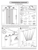
UNDERSTANDING YOUR RAILS
LEFT RAIL
RIGHT RAIL
LEFT AND RIGHT RAILS JOINED BY SPLICER
Splicer Holes
Splicer Holes

American Pro Decor assumes no liability for improper installation.
6”
16”
16”
16”
12”
16”
16”
16”
H Dimension + 1⅜”
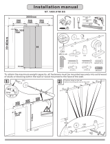
INSTALLATION
Before beginning installation,
attach the door stops [C] to
both rails [M].
1
2
Using a power drill with a 4mm drill bit, drill holes as indicated.
Using a pencil, mark the locations where you will drill holes as indicated.

American Pro Decor assumes no liability for improper installation.
1. Install the rst rail, and mounting brackets [E].
2. Line up the second rail against the rst and install with mounting brackets. Secure the two rails with the splicer [L].
3
Mounting Bracket [E]
Drill holes into the doors as indicated. Attach the door rollers [A].
It is suggested that the door rollers [A] be mounted 5" from the edge of the doors to the neck of the rollers.
4
NOTE: Trimming the rail will alter the position of the roller hardware. Adjust accordingly.
NOTE: If mounting to a wall, fasteners must be mounted into solid wood studs, wall blocking or, a wood header
board when additional projection is needed. (Example: When using as TV shutters)
(x8)
Splicer [L]

5
American Pro Decor assumes no liability for improper installation.
3⅛"
3⅛"
FOR ¾" DOORS
FOR 1" DOORS
Allow a minimum 3-1/8" clearance above the doors.

6
American Pro Decor assumes no liability for improper installation.
Attach the anti-jump disks [B] to the doors.
Attach the doors to the rail [L] and lock the anti-jump disks [B] into position. Doors should be routed beforehand
if using the routed door guides [G].
5
6
Roller Strap [A]
Anti-Jump Disk [B]
Anti-Jump Disk [B]
(x2)
(x2)

7
American Pro Decor assumes no liability for improper installation.
Use the hole covers [K] to give the rail a
nished look.
Once cut, add the end caps [D] to the ends of the rail and secure with a
set screw.
7
8
Routed Door Guide [G]
Hole Covers [K]
The rail can be trimmed if necessary using a band saw
or hacksaw. Use blades suitable for iron or stainless
steel depending on your rail.
9
End Cap [D]
End Cap [D]
2½" Max
2½" Max
If using the routed door guides [G], install them at this time.
Repeat steps 4-7 for additional door.
NOTE: If you are trimming the rail, do so equally. Each
rail can be trimmed equally up to 2½" from one (1) side
of each length of rail. Holes for splicer must remain intact
on one side of the rail. However; trimming will alter the
position of the roller hardware. Adjust accordingly.

American Pro Decor assumes no liability for improper installation.
8
Maximum T.V. size of 60" with a width of 56"
/