Page is loading ...

MOTION CONTROL ENGINEERING, INC.
11380 WHITE ROCK ROAD
RANCHO CORDOVA, CA 95742
TELEPHONE (916) 463-9200 FAX (916) 463-9201
CONTROLLER INSTALLATION MANUAL
VFMC-1000-PTC SERIES M (OPEN LOOP)
VFMC-1000-PTC SERIES M (FLUX VECTOR)
VARIABLE FREQUENCY PROGRAMMABLE TRACTION CONTROLLER
PART # 42-02-2P21 REVISION D.7 SEPTEMBER 2007
Applicable to EMS, IDM , Yaskawa, MagneTek (GPD515+ / G5+),
MagneTek (HPV 900), Yaskawa (F7) and TORQMAX AC Drives

42-02-2P21 TABLE OF CONTENTS • i
TABLE OF CONTENTS
IMPORTANT NOTES & PRECAUTIONS .................................. xi
SECTION 1
PRODUCT DESCRIPTION
1.0 General Information ...............................................1-1
1.1 Car Controller Physical Description ...................................1-2
1.2 Car Controller Functional Description..................................1-9
1.2.1 Car Operation Control (COC) .................................1-10
1.2.2 Car Communication Control (CCC) .............................1-10
1.2.3 Programming and Diagnostics Tools ...........................1-11
1.2.4 Duplexing ................................................1-11
1.2.5 Car Motion Control (CMC) ...................................1-11
1.2.6 VVVF Drive ...............................................1-11
1.2.7 Typical Sequence of Operation................................1-11
1.3 Landing Systems ................................................1-12
1.3.1 LS-STAN ................................................1-13
1.3.2 LS-QUTE ................................................1-13
SECTION 2
INSTALLATION
2.0 General Information ...............................................2-1
2.0.1 Site Selection ..............................................2-1
2.0.2 Environmental Considerations .................................2-1
2.0.3 Recommended Tools and Test Equipment ........................2-2
2.0.4 Wiring Prints...............................................2-3
2.1 Controller Installation ..............................................2-4
2.1.1 Controller Wiring Guidelines...................................2-4
2.2 General Wiring Guidelines ..........................................2-6
2.2.1 Ground Wiring .............................................2-6
2.2.2 AC Motor and Brake Wiring ...................................2-7
2.2.3 Installing and Wiring the Speed Sensor ..........................2-7
2.2.4 Installing the Brake Switch ....................................2-9
2.2.5 Installing and Wiring the Encoder ..............................2-10
2.3 Hoistway Control Equipment Installation ..............................2-11
2.3.1 Installing the Landing System .................................2-11
2.3.2 Installing the Hoistway Limit Switches ..........................2-11
2.3.3 Installing the Landing System Control Box (LS-QUTE) ..............2-11
2.3.4 Installing the Magnetic Strips on the Steel Tape ...................2-12
2.3.5 TM Switch Wiring and Adjustment (If Used) ......................2-12

• TABLE OF CONTENTS 42-02-2P21ii
2.3.6 Door Operator Diode Installation (If Used) .......................2-12
2.3.7 Door Position Monitor Switch (If Used).......................... 2-13
SECTION 3
START-UP
3.0 General Information ...............................................3-1
3.1 Ground Check ...................................................3-1
3.2 Before Applying Power.............................................3-2
3.3 Applying Power - Preparing to Move the Car on Inspection .................3-2
3.3.1 Initial Power up.............................................3-3
3.3.2 Drive Interface Board Details ..................................3-4
3.4 Inspection Operation - G5 / GPD515 Drive .............................3-5
3.4.1 Drive Parameter Settings .....................................3-5
3.4.2 Verifying the Critical G5 / GPD515 Drive Parameters ................3-6
3.4.3 Moving the Car on Inspection Operation (G5 / GPD515) .............3-9
3.5 Inspection Operation - MagneTek HPV 900 Drive .......................3-12
3.5.1 Drive Parameter Settings ....................................3-12
3.5.2 Verifying the Critical MagneTek HPV 900 Drive Parameters .........3-12
3.5.3 Moving the Car on Inspection Operation (HPV 900) ................3-13
3.6 Inspection Operation - TORQMAX F4 Drive ...........................3-15
3.6.1 Drive Parameter Settings ....................................3-15
3.6.2 Verifying the Critical TORQMAX F4 Drive Parameters.............. 3-16
3.6.3 Moving the Car on Inspection Operation (TORQMAX F4) ...........3-16
3.7 Inspection Operation - Yaskawa F7 Drive .............................3-20
3.7.1 Drive Parameter Settings ....................................3-20
3.7.2 Verifying the Critical Yaskawa F7 Drive Parameters................3-20
3.7.3 Moving the Car on Inspection Operation (Yaskawa F7) ............. 3-24
3.8 Inspection Operation - TORQMAX F5 Drive ...........................3-27
3.8.1 Drive Parameter Settings ....................................3-27
3.8.2 Verifying the Critical TORQMAX F5 Drive Parameters.............. 3-27
3.8.3 Moving the Car on Inspection Operation (TORQMAX F5) ...........3-28
SECTION 4
FINAL ADJUSTMENT
4.0 General Information ...............................................4-1
4.1 Preparing to Run on High Speed and Automatic Operation .................4-1
4.1.1 Door Operator .............................................4-1
4.1.2 HC-ACI and HC-ACIF Board Adjustments ........................4-1
4.1.3 Diagnostic Messages and Input/output Signals ....................4-2
4.1.4 A Few Words about Absolute Floor Encoding .....................4-2
4.1.5 Registering Car Calls ........................................4-3
4.1.6 Test Mode Operation ........................................4-3

42-02-2P21 TABLE OF CONTENTS • iii
4.2 Explanation of G5 / GPD515 Drive Parameters and S Curves ...............4-4
4.2.1 Setting the Speed Levels .....................................4-4
4.2.2 Adjusting Acceleration and Deceleration Rate .....................4-6
4.2.3 Adjusting the S-curves (G5 / GPD515) ..........................4-6
4.3 Final Adjustments (G5 / GPD515) ....................................4-8
4.3.1 Final Preparation for Running on Automatic Operation (G5 / GPD515) . . 4-8
4.3.2 Switching to Automatic Operation (G5 / GPD515) ..................4-8
4.3.3 Brake Adjustment for 125% Load (G5 / GPD515) ..................4-9
4.3.4 Bringing the Car up to High Speed (G5 / GPD515) ..................4-9
4.3.5 Load Testing (G5 / GPD515) .................................4-12
4.4 Final Elevator Inspection Procedure (G5 / GPD515) .....................4-14
4.4.1 Inspection Leveling over Speed Test (G5 / GPD515) ...............4-14
4.4.2 Terminal Slowdown Limit Switches (G5 / GPD515) ................4-14
4.4.3 Emergency Terminal Limit Switch Monitor (G5 / GPD515) ...........4-15
4.4.4 Contract Speed Buffer Test (G5 / GPD515) ......................4-15
4.4.5 Governor and Car Safety Tests (G5 / GPD515) ...................4-16
4.4.6 Phase Loss Detection Tests (G5 / GPD515) .....................4-18
4.5 Explanation of HPV 900 Drive Parameters and S Curves .................4-19
4.5.1 Setting the Speed Levels ....................................4-19
4.5.2 Adjusting Acceleration and Deceleration Rates ...................4-20
4.5.3 Adjusting the Jerk Parameters ................................4-20
4.6 Final Adjustments (HPV 900) .......................................4-21
4.6.1 Final Preparation for Running on Automatic Operation (HPV 900) .....4-21
4.6.2 Switching to Automatic Operation (HPV 900) .....................4-22
4.6.3 Brake Adjustment for 125% Load (HPV 900) .....................4-22
4.6.4 Bringing the Car up to High Speed (HPV 900) ....................4-22
4.6.5 Adaptive Tuning (HPV 900) ..................................4-25
4.6.6 Load Testing (HPV 900) .....................................4-25
4.7 Final Elevator Inspection Procedure (HPV 900) .........................4-26
4.7.1 Inspection Leveling over Speed Test (HPV 900) ..................4-26
4.7.2 Terminal Slowdown Limit Switches (HPV 900) ....................4-27
4.7.3 Emergency Terminal Limit Switch Monitor (HPV 900) ..............4-27
4.7.4 Contract Speed Buffer Test (HPV 900) ..........................4-27
4.7.5 Governor and Car Safety Tests (HPV 900) .......................4-29
4.7.6 Phase Loss Detection Tests (HPV 900) .........................4-30
4.8 Explanation of TORQMAX F4 Drive Parameters and S Curves .............4-31
4.8.1 Setting the Speed Levels ....................................4-31
4.8.2 Adjusting Acceleration and Deceleration Rates ...................4-32
4.8.3 Adjusting the Jerk Parameters ................................4-32
4.9 Final Adjustments (TORQMAX F4) ..................................4-33
4.9.1 Final Preparation for Running on Automatic Operation (TORQMAX F4) 4-33
4.9.2 Switching to Automatic Operation (TORQMAX F4) ................4-34
4.9.3 Brake Adjustment for 125% Load (TORQMAX F4) .................4-34
4.9.4 Bringing the Car up to High Speed (TORQMAX F4) ................4-34
4.9.5 Load Testing (TORQMAX F4) ................................4-37

• TABLE OF CONTENTS 42-02-2P21iv
4.10 Final Elevator Inspection Procedure (TORQMAX F4) ....................4-39
4.10.1 Inspection Leveling over Speed Test (TORQMAX F4) ..............4-39
4.10.2Terminal Slowdown Limit Switches (TORQMAX F4) ............... 4-39
4.10.3Emergency Terminal Limit Switch Monitor (TORQMAX F4) ..........4-40
4.10.4 Contract Speed Buffer Test (TORQMAX F4) .....................4-41
4.10.5 Governor and Car Safety Tests (TORQMAX F4) .................. 4-42
4.10.6Phase Loss Detection Tests (TORQMAX F4) ....................4-43
4.11 Explanation of Yaskawa F7 Drive Parameters and S Curves ...............4-44
4.11.1 Setting the Speed Levels ....................................4-44
4.11.2Adjusting Acceleration and Deceleration Rate ....................4-46
4.11.3 Adjusting the S-curves (Yaskawa F7) ........................... 4-46
4.12 Final Adjustments (Yaskawa F7) ....................................4-48
4.12.1 Final Preparation for Running on Automatic Operation (Yaskawa F7) . . 4-48
4.12.2Switching to Automatic Operation (Yaskawa F7) ..................4-48
4.12.3 Brake Adjustment for 125% Load (Yaskawa F7) ..................4-49
4.12.4 Bringing the Car up to High Speed (Yaskawa F7) ................. 4-49
4.12.5Load Testing (Yaskawa F7) ..................................4-52
4.13 Final Elevator Inspection Procedure (Yaskawa F7) ......................4-54
4.13.1 Inspection Leveling over Speed Test (Yaskawa F7) ................4-54
4.13.2Terminal Slowdown Limit Switches (Yaskawa F7) .................4-54
4.13.3Emergency Terminal Limit Switch Monitor (Yaskawa F7)............4-55
4.13.4 Contract Speed Buffer Test (Yaskawa F7) .......................4-55
4.13.5 Governor and Car Safety Tests (Yaskawa F7) ....................4-56
4.13.6Phase Loss Detection Tests (Yaskawa F7) ...................... 4-58
4.14 Explanation of TORQMAX F5 Drive Parameters and S Curves .............4-59
4.14.1 Setting the Speed Levels ....................................4-59
4.14.2Adjusting Acceleration and Deceleration Rates ...................4-60
4.14.3 Adjusting the Jerk Parameters ................................4-60
4.15 Final Adjustments (TORQMAX F5) ..................................4-61
4.15.1 Final Preparation for Running on Automatic Operation (TORQMAX F5) 4-61
4.15.2Switching to Automatic Operation (TORQMAX F5) ................4-62
4.15.3 Brake Adjustment for 125% Load (TORQMAX F5) ................4-62
4.15.4 Bringing the Car up to High Speed (TORQMAX F5) ................ 4-62
4.15.5Load Testing (TORQMAX F5) ................................4-65
4.16 Final Elevator Inspection Procedure (TORQMAX F5) ....................4-67
4.16.1 Inspection Leveling over Speed Test (TORQMAX F5) ..............4-67
4.16.2Terminal Slowdown Limit Switches (TORQMAX F5) ............... 4-67
4.16.3Emergency Terminal Limit Switch Monitor (TORQMAX F5) ..........4-68
4.16.4 Contract Speed Buffer Test (TORQMAX F5) .....................4-69
4.16.5 Governor and Car Safety Tests (TORQMAX F5) .................. 4-70
4.16.6Phase Loss Detection Tests (TORQMAX F5) ....................4-71

42-02-2P21 TABLE OF CONTENTS • v
SECTION 5
THE COMPUTER
5.0 About the PTC Series .............................................5-1
5.1 The MC-PCA Computer Panel.......................................5-1
5.1.1 Indicators .................................................5-1
5.1.1.1 Computer on Light ....................................5-1
5.1.1.2 Vertical Status Indicator Lights ..........................5-1
5.1.1.3 Diagnostics LCD Display ...............................5-2
5.1.2 Switches, Buttons & Adjustments...............................5-2
5.1.2.1 Computer Reset Pushbutton ............................5-2
5.1.2.2 N, S, +, and – Pushbuttons .............................5-2
5.1.2.3 Mode Selection F1-F8 Function Switches ..................5-3
5.1.2.4 LCD Contrast Adjustment Trimpot........................5-3
5.1.3 Terminals .................................................5-3
5.1.3.1 Power Supply Terminal ................................5-3
5.1.3.2 Communication Port for Duplexing .......................5-3
5.1.3.3 Com Port 1 and 2 .....................................5-3
5.1.4 Status Displays.............................................5-3
5.2 Computer Security ................................................5-3
5.2.1 Password .................................................5-4
5.3 Diagnostic Mode .................................................5-4
5.3.1 Getting into Diagnostic Mode ..................................5-4
5.3.2 Function of N Pushbutton.....................................5-4
5.3.3 Function of S Pushbutton .....................................5-5
5.3.4 Function of + Pushbutton .....................................5-5
5.3.5 Function of – Pushbutton .....................................5-5
5.3.6 Format of LCD Display .......................................5-5
5.3.6.2 Status Message......................................5-6
5.3.6.3 Elevator Position ....................................5-13
5.3.6.4 Computer Internal Memory.............................5-14
5.3.7 Troubleshooting Using the Computer's Internal Memory ............5-15
5.3.8 Troubleshooting Specific Problems ............................5-17
5.3.8.1 Problem: the BFD/TFD Error Message Is Flashing on the Display5-17
5.3.8.2 Problems with Calls ..................................5-19
5.3.8.3 Problems with Doors .................................5-19
5.3.9 Setting Parameters (Options) to Default Values...................5-19
5.4 Program Mode ..................................................5-20
5.4.1 General Description of Program Mode ..........................5-20
5.4.1.1 Viewing Menus on the LCD Display......................5-20
5.4.1.2 Viewing Options Within a Menu.........................5-21
5.4.1.3 Changing a Value ...................................5-21
5.4.1.4 Saving the New Values ...............................5-21
5.4.1.5 Restoring Original Values .............................5-22
5.4.1.6 Step-by-step Example ................................5-22

• TABLE OF CONTENTS 42-02-2P21vi
5.4.2 Basic Feature Menu Options .................................5-23
5.4.2.1 Simplex or Duplex? ..................................5-23
5.4.2.2 Operation (Dispatching Operation) ......................5-23
5.4.2.3 Top Landing Served? ................................5-23
5.4.2.4 Car Doors Are Walk-thru?............................. 5-23
5.4.2.5 Car Serves Frnt/flr 1? ................................5-23
5.4.2.6 Car Serves Rear/flr 1?................................5-23
5.4.2.7 Parking Floor....................................... 5-24
5.4.2.8 Alt. Parking Floor....................................5-24
5.4.2.9 Secondary Parking Floor.............................. 5-24
5.4.2.10 Lobby Floor .......................................5-24
5.4.2.11 Car Identifier ...................................... 5-24
5.4.2.12 Number of IOX Boards? .............................5-24
5.4.2.13 Number of I4O Boards?..............................5-24
5.4.2.14 Number of AIOX Boards? ............................5-24
5.4.3 Fire Service Menu Options...................................5-24
5.4.3.1 Fire Service Operation?............................... 5-24
5.4.3.2 Fire Phase 1 Main Floor ..............................5-24
5.4.3.3 Fire Phase 1 Alt. Floor................................5-24
5.4.3.4 Fire Svce. Code.....................................5-25
5.4.3.5 Fire Phase I 2nd Alt. Floor............................. 5-25
5.4.3.6 Bypass Stop Sw. On Phase 1? ......................... 5-25
5.4.3.7 Honeywell Fire Operation? ............................5-25
5.4.3.8 New York City Fire Phase 2 and ANSI 89? ................5-25
5.4.3.9 White Plains, Ny Fire Code? ........................... 5-25
5.4.3.10 Mass 524 CMR Fire Code? ...........................5-25
5.4.4 Door Operation Menu Options ................................5-25
5.4.4.1 Nudging?..........................................5-25
5.4.4.2 Stuck Photo Eye Protection?........................... 5-26
5.4.4.3 Sequential Door Oper. (F/R) ...........................5-26
5.4.4.4 Car Call Cancels Door Time? .......................... 5-26
5.4.4.5 Nudging During Fire Ph. 1?............................ 5-26
5.4.4.6 Retiring Cam Option? ................................ 5-26
5.4.4.7 Pre-opening? .......................................5-26
5.4.4.8 Mechanical Safety Edge? .............................5-26
5.4.4.9 Nudging Output/buzzer Only? ..........................5-27
5.4.4.10 D.C.B. Cancels Door Time? ..........................5-27
5.4.4.11 Leave Doors Open on MGS? ..........................5-27
5.4.4.12 Leave Doors Open on PTI/ESS? ....................... 5-27
5.4.4.13 Nudging During Fire Phase 2? ........................ 5-27
5.4.4.14 Dir. Preference until DLK?............................ 5-27
5.4.4.15 Fully Manual Doors? ................................5-27
5.4.4.16 Cont. D.C.B. to Close Doors? .........................5-27
5.4.4.17 Cont. D.C.B. for Fire Ph 1? ...........................5-27
5.4.4.18 Moment. D.O.B. Door Opening ? .......................5-27
5.4.4.19 Doors to Open if Parked: ............................5-28
5.4.4.20 Doors to Open on Main Fire?..........................5-28
5.4.4.21 Doors to Open on Alt Fire? ........................... 5-28
5.4.4.22 Leave Doors Open on CTL? ..........................5-28
5.4.4.23 Limited Door Reopen Option .......................... 5-28
5.4.4.24 Reduce HCT with Photo Eye .......................... 5-28
5.4.4.26 Doors to Open If No Demand ......................... 5-28
5.4.4.27 Const. Press Op. Bypass PHE? .......................5-28
5.4.4.28 Door Type Is Horizontal / Vertical ......................5-29
5.4.4.30 Rear Door Mech. Coupled? ...........................5-29
5.4.4.31 Prevent DCP Til Doors Close? ........................ 5-29
5.4.4.32 Moment. D.C.B to Close Doors? .......................5-29

42-02-2P21 TABLE OF CONTENTS • vii
5.4.4.33 Doors to Latch DOF?................................5-29
5.4.4.34 Doors to Latch DCF?................................5-29
5.4.5.1 Short Door Timer (Range: 0.5-120.0 Seconds) .............5-29
5.4.5.2 Car Call Door Timer (Range: 0.5-120.0 Seconds) ...........5-29
5.4.5.3 Hall Call Door Timer (Range: 0.5-120.0 Seconds) ...........5-29
5.4.5.4 Lobby Door Timer (Range: 0.5-120.0 Seconds) ............5-29
5.4.5.5 Nudging Timer (Range: 10-240 Seconds) .................5-29
5.4.5.6 Time out of Svce. Timer ..............................5-30
5.4.5.7 Motor Limit Timer (Range: 1.0 - 6.0 Minutes)...............5-30
5.4.5.8 Mgr Output Timer (Range: 0 - 27 Minutes) ................5-30
5.4.5.9 Door Hold Input Timer (Range: 0-240 Seconds) ............5-30
5.4.5.10 Parking Delay Timer (Range: 0.0-6.0 Minutes) ............5-30
5.4.5.11 Fan/light Output Timer (Range : 1.0-10.0 Minutes) .........5-30
5.4.5.12 Hospital Emerg. Timer (Range : 0.0-10.0 Minutes) .........5-30
5.4.5.13 Door Open Protection Timer (Range 8 - 30 Seconds) .......5-30
5.4.5.14 CTL Door Open Timer (Range: 2.0 - 60.0 Seconds) ........5-30
5.4.5.15 Door Buzzer Timer (Range: 0.0 - 30.0 Seconds) ...........5-31
5.4.6 Gongs/lanterns Menu Options ................................5-31
5.4.6.1 Mounted in Hall or Car? ...............................5-31
5.4.6.2 Double Strike on Down? ..............................5-31
5.4.6.3 PFG Enable Button? .................................5-31
5.4.6.4 Egress Floor Arrival Gong?.............................5-31
5.4.7 Spare Inputs Menu Options ..................................5-31
5.4.8 Spare Outputs Menu Options .................................5-35
5.4.9 Extra Features Menu Options.................................5-38
5.4.9.1 PI Output Type .....................................5-38
5.4.9.2 Floor Encoding Inputs? ...............................5-38
5.4.9.3 Encode All Floors?...................................5-38
5.4.9.4 Intermediate Speed? .................................5-38
5.4.9.5 Emergency Power Operation? / Emergency Power Return Floor 5-38
5.4.9.6 Light Load Weighing? / Light Load Car Call Limit ...........5-38
5.4.9.7 Photo Eye Anti-nuisance? / Consec Stops W/O PHE Limit ....5-38
5.4.9.8 Earthquake Operation ................................5-39
5.4.9.9 Counterweighted Drum Machine? .......................5-39
5.4.9.10 MG Shutdown Operation? / MGS Return Floor ............5-39
5.4.9.11 Peripheral Device?..................................5-40
5.4.9.12 Automatic Floor Stop Option? .........................5-40
5.4.9.13 CC Cancel W/dir Reversal?...........................5-40
5.4.9.14 Cancel Car Calls Behind Car?.........................5-40
5.4.9.15 CE Electronics Interface? ............................5-40
5.4.9.16 Massachusetts Ems Service? / Ems Service Floor #........5-40
5.4.9.17 Master Software Key ................................5-40
5.4.9.18 PI Turned off If No Demand? ..........................5-41
5.4.9.19 Hospital Emerg. Operation?...........................5-41
5.4.9.20 Fire Bypasses Hospital? .............................5-42
5.4.9.21 High Speed Delay after Run? .........................5-42
5.4.9.22 Single Speed A.C. Option? ...........................5-42
5.4.9.23 Sabbath Operation? .................................5-42
5.4.9.24 Intermediate Speed Between Floors? ...................5-42
5.4.9.25 Leveling Sensor Enabled/disabled......................5-43
5.4.9.26 KCE Enable / Disable ...............................5-43
5.4.9.27 Analog Load Weigher? None / Mce / K-tech ..............5-43
5.4.9.29 Ind. Bypass Security? Yes / No ........................5-43
5.4.9.30 ATS. Bypass Security? Yes / No .......................5-43
5.4.9.31 Car to Floor Return Floor.............................5-43
5.4.9.32 Scrolling Speed (Slow / Normal / Fast) ..................5-43
5.4.9.33 OFRP Between FLRS ...............................5-43

• TABLE OF CONTENTS 42-02-2P21viii
5.5 External Memory Mode ...........................................5-44
5.5.1 Getting into External Memory Mode ............................5-44
5.5.2 Function of N Pushbutton....................................5-44
5.5.3 Function of S Pushbutton....................................5-44
5.5.4 Function of + Pushbutton ....................................5-44
5.5.5 Function of – Pushbutton ....................................5-44
5.5.6 Troubleshooting Using External Memory Mode ...................5-45
5.6 System Mode...................................................5-48
5.6.1 Building Security Menu...................................... 5-48
5.6.1.1 Viewing the Building Security Menu......................5-48
5.6.1.2 Programming and Viewing the Security Codes .............5-49
5.6.2 Passcode Request Menu ....................................5-50
5.6.3 Load Weigher Thresholds ...................................5-51
5.6.4 Analog Load Weigher Learn Function .......................... 5-52
5.7 Duplexing......................................................5-54
5.7.1 Dispatching Algorithm ......................................5-54
5.7.2 Hardware Connections ......................................5-54
5.7.3 Troubleshooting ...........................................5-54
SECTION 6
ON-BOARD DIAGNOSTICS TROUBLESHOOTING
6.0 General Information ...............................................6-1
6.1 Tracing Signals in the Controller .....................................6-1
6.2 Door Logic ......................................................6-3
6.3 Call Logic.......................................................6-7
6.3.1 Normal Operation...........................................6-7
6.3.2 Preparation for Troubleshooting Call Circuits......................6-7
6.3.3 Troubleshooting ............................................6-7
6.4 Using the Optional CRT for Troubleshooting ...........................6-12
6.4.1 Graphic Display of Elevator (F3) Screen ........................6-12
6.4.2 MCE Special Events Calendar Entries (F7 - 1) Screen..............6-12
6.5 Troubleshooting the G5 / GPD515 AC Drive ...........................6-14
6.5.1 Car Does Not Move on Inspection .............................6-14
6.5.2 Car Does Not Reach Contract Speed...........................6-16
6.5.3 Car Overshoots or the Drive Trips “Over Voltage” on Acceleration.....6-16
6.5.4 Drive Trips “Over Voltage” or the Car Overshoots on Deceleration ....6-16
6.5.5 Oscillations in the Car at Contract Speed -
Closed Loop System Only (Flux Vector Applications) ...............6-17
6.5.6 Oscillations in the Car - Open Loop System ......................6-17
6.5.7 Drive Trips “Over Voltage” by Clipping the Door Locks ..............6-17
6.5.8 Alarms and Faults ......................................... 6-18
6.6 Troubleshooting the MagneTek HPV900 Ac Drive .......................6-19
6.6.1 Car Does Not Move on Inspection .............................6-19
6.6.2 Car Does Not Reach Contract Speed...........................6-20
6.6.3 Car Overshoots or the Drive Trips “Over Voltage” on Acceleration.....6-21

42-02-2P21 TABLE OF CONTENTS • ix
6.6.4 Drive Trips “Over Voltage” or the Car Overshoots on Deceleration ....6-21
6.6.5 Oscillations in the Car at Contract Speed ........................6-21
6.6.6 Drive Trips “Over Voltage” by Clipping the Door Locks ..............6-22
6.6.7 Alarms and Faults..........................................6-22
6.7 Troubleshooting the TORQMAX F4 AC Drive ..........................6-22
6.7.1 Car the Does Not Move on Inspection ..........................6-22
6.7.2 Car Does Not Run / Reach Contract Speed ......................6-24
6.7.3 Car Overshoots or the Drive Trips on 'E. Ol' or 'E. Op' on Acceleration . 6-25
6.7.4 Drive Trips 'E.op' or the Car Overshoots on Deceleration ............6-25
6.7.5 Oscillations in the Car at Contract Speed ........................6-26
6.7.6 Drive Trips “Over Voltage” by Clipping the Door Locks ..............6-26
6.7.7 Alarms and Faults..........................................6-26
6.7.8 Troubleshooting Flowcharts - TORQMAX F4 Drive ................6-28
6.8 Troubleshooting the Yaskawa F7 AC Drive ............................6-37
6.8.1 Car Does Not Move on Inspection .............................6-37
6.8.2 Car Does Not Reach Contract Speed ...........................6-38
6.8.3 Car Overshoots or the Drive Trips “Over Voltage” on Acceleration.....6-39
6.8.4 Drive Trips “Over Voltage” or the Car Overshoots on Deceleration ....6-39
6.8.5 Oscillations in the Car at Contract Speed - Closed Loop System Only
(Flux Vector Applications)....................................6-40
6.8.6 Oscillations in the Car - Open Loop System ......................6-40
6.8.7 Drive Trips “Over Voltage” by Clipping the Door Locks ..............6-40
6.8.8 Alarms and Faults..........................................6-40
6.9 Troubleshooting the TORQMAX F5 AC Drive ..........................6-42
6.9.1 Car the Does Not Move on Inspection ..........................6-42
6.9.2 Car Does Not Run / Reach Contract Speed ......................6-44
6.9.3 Car Overshoots or the Drive Trips on 'E. Ol' or 'E. Op' on Acceleration . 6-45
6.9.4 Drive Trips 'E.op' or the Car Overshoots on Deceleration ............6-45
6.9.5 Oscillations in the Car at Contract Speed ........................6-45
6.9.6 Drive Trips “Over Voltage” by Clipping the Door Locks ..............6-45
6.9.7 Error Messages and Their Causes .............................6-45
6.9.8 Troubleshooting Flowcharts - TORQMAX F5 Drive ................6-47
6.10 Using the MLT Data Trap..........................................6-56
6.11 PC Board Quick References .......................................6-59

• TABLE OF CONTENTS 42-02-2P21x
APPENDIX
Appendix A Original Programmed Values and the Record of Changes ............A-1
Appendix B Quick Reference for G5+ / GPD515+ Drive Parameters .............A-6
Appendix C Quick Reference for HPV 900 Drive Parameters ..................A-14
Appendix D Quick Reference for TORQMAX Drive Parameters ................A-20
Appendix E Nomenclature .............................................A-23
Appendix F Elevator Security Information and Operation .....................A-24
Appendix G Flex-talk Option ...........................................A-27
G.1 Introduction and Theory of Operation ...........................A-27
G.2 Diagnostics...............................................A-28
G.3 Volume Control............................................A-29
G.4 Troubleshooting ...........................................A-29
G.5 Peripheral Equipment .......................................A-29
Appendix H LS-QUTE Landing System Assembly Drawings ...................A-30
Appendix I POWERBACK R4 Regenerative Drive ..........................A-32
Appendix J Quick Reference for Yaskawa F7 Drive Parameters ...............A-36
Appendix K Quick Reference for PowerBack R6 Regenerative
AC Drive Parameters (Series M and IMC-AC-R) ..................A-44
Appendix L Quick Reference for TORQMAX F5 Drive Parameters ..............A-47
INDEX

42-02-2P21 TABLE OF CONTENTS • xi
NOTE
WARNING
IMPORTANT PRECAUTIONS & NOTES
We strongly recommend that you read this manual carefully before proceeding with installation.
Throughout this manual you will see icons followed by a WARNING, CAUTION or NOTE.
These icons denote the following:
Operating procedures and practices which, if not done correctly, may result in
personal injury or substantial damage to equipment.
Operating procedures and practices which, if not observed, may result in some
damage to equipment.
Procedures, practices or information which are intended to be immediately
helpful and informative.
The following general rules and safety precautions must be observed for safe and reliable
operation of your system.
This controller may be shipped without the final running program. However, you
may install the unit, hookup and run your elevator on Inspection operation. Call
MCE about a week before you are ready to turn the elevator over to full automatic
operation so the running program can be shipped to you.
If you need to change a program chip on a computer board, make sure that you
read the instructions and know exactly how to install the new chip. Plugging these
devices in backwards may damage your chip.
Elevator control products must be installed by experienced field personnel. This
manual does not address code requirements. The field personnel must know all
the rules and regulations pertaining to the safe installation and running of
elevators.
This equipment is an O.E.M. product designed and built to comply with ASME
A17.1 and National Electrical Code CAN/CSA-B44.1/ASME-A17.5 and must be
installed by a qualified contractor. It is the responsibility of the contractor to make
sure that the final installation complies with any local codes and is installed safely.
The 3-phase AC power supply to this equipment must come from a fused
disconnect switch or a circuit breaker that is sized in conformance with all
applicable national, state and local electrical codes, to provide the necessary
overload protection for the drive unit and motor. Incorrect motor branch circuit
protection will void the warranty and may create a hazardous condition.
Proper grounding is vitally important to the safe and successful operation of your
system. Bring your ground wire to the system subplate. You must choose the
proper conductor size and minimize the resistance to ground by using shortest
possible routing. See National Electrical Code Article 250-95, or the related local
applicable code.
For proper operation of the VVVF AC Drive Unit in your controller, you must make
sure that a direct solid ground is provided in the machine room to properly ground
the controller and motor. Indirect grounds such as the building structure or a

• TABLE OF CONTENTS 42-02-2P21xii
CAUTION
NOTE
water pipe may not provide proper grounding and could act as an antenna to
radiate RFI noise, thus disturbing sensitive equipment in the building. Improper
grounding may also render any RFI filter ineffective.
Before applying power to the controller, physically check all power resistors and
other components located in the resistor cabinet and inside the controller.
Components loosened during shipment may cause damage.
Do not change drive parameters while the elevator is running. Incorrect values of
drive parameters can cause erratic elevator operation.
For proper operation of the VVVF AC Drive Unit in your controller, you must make
sure that the incoming power to the controller and outgoing power wires to the
motor are in their respective grounded conduits separate from all other control
wires.
You must not connect the output triacs directly to a hot bus (2, 3 or 4 bus). This
can damage the triacs. PIs, direction arrows and terminals 40 & 42 are examples
of outputs that can be damaged this way. Note: miswiring terminal 39 into 40 can
damage the fire warning indicator triac.
Your HC-PCI/O and HC-CI/O-E boards are equipped with quick disconnect
terminals. During the original installation, you may want to remove the terminal
connector, hook up your field wires to it, test it for no shorts to ground (1 bus) and
to terminals 2, 3 and 4 before plugging these terminals back into the PC boards.
The controller should be installed nearest to the hoist motor, so that length of the
connecting wires should not exceed more than 100 feet. If the wire from the
controller to the hoist motor is more than 100 feet, contact MCE.
ENVIRONMENTAL CONSIDERATIONS:
Keep the machine room clean. Controllers are generally in NEMA 1 enclosures. Do not install
the controller in a dusty area. Do not install the controller in a carpeted area. Keep room
temperature between 32
F to 104 F (0 to 40 C). Avoid condensation on the equipment.
Do not install the controller in a hazardous location and where excessive amounts of vapors or
chemical fumes may be present. Make sure power line fluctuations are within +
10%.
CONTROLLER OR GROUP ENCLOSURES WITH AIR CONDITIONING
If your controller or group enclosure is equipped with an air conditioning unit, observe the
following precautions (failure to do so can result in water condensation inside the
enclosure):
• Ensure the integrity of the NEMA 12 or 4 enclosure is maintained by using sealed
knockouts and by sealing any holes created during installation.
• Do not run the air conditioner unit when the doors are open.
• To avoid damaging the compressor, if the air conditioner is turned off while it is running,
wait at least five minutes before turning power on again.
• Observe the manufacture’s recommended maintenance and optimum thermostat setting
of 75
o
F (see Operator’s Manual).
• Ensure the air conditioner unit’s drain hose remains open.

42-02-2P21 TABLE OF CONTENTS • xiii
LIMITED WARRANTY
Motion Control Engineering (manufacturer) warrants its products for a period of 15 months from the date of
shipment from its factory to be free from defects in workmanship and materials. Any defect appearing more than
15 months from the date of shipment from the factory shall be deemed to be due to ordinary wear and tear.
Manufacturer, however, assumes no risk or liability for results of the use of the products purchased from it,
including, but without limiting the generality of the forgoing: (1) The use in combination with any electrical or
electronic components, circuits, systems, assemblies or any other material or equipment (2) Unsuitability of this
product for use in any circuit, assembly or environment. Purchasers’ rights under this warranty shall consist
solely of requiring the manufacturer to repair, or in manufacturer's sole discretion, replace free of charge, F.O.B.
factory, any defective items received at said factory within the said 15 months and determined by manufacturer
to be defective. The giving of or failure to give any advice or recommendation by manufacturer shall not
constitute any warranty by or impose any liability upon the manufacturer. This warranty constitutes the sole and
exclusive remedy of the purchaser and the exclusive liability of the manufacturer, AND IN LIEU OF ANY AND
ALL OTHER WARRANTIES, EXPRESSED, IMPLIED, OR STATUTORY AS TO MERCHANTABILITY,
FITNESS, FOR PURPOSE SOLD, DESCRIPTION, QUALITY PRODUCTIVENESS OR ANY OTHER MATTER.
In no event will the manufacturer be liable for special or consequential damages or for delay in performance of
this warranty.
Products that are not manufactured by MCE (such as drives, CRT's, modems, printers, etc.) are not covered
under the above warranty terms. MCE, however, extends the same warranty terms that the original
manufacturer of such equipment provide with their product (refer to the warranty terms for such products in their
respective manual).

42-02-2P21 PRODUCT DESCRIPTION • 1-1
SECTION 1
PRODUCT DESCRIPTION
1.0 GENERAL INFORMATION
MCE’s VFMC-1000-PTC (Programmable Traction Controller for AC Elevators) is designed to
exhibit the characteristics listed below in a traction elevator installation. The PTC controller has
been designed to save time in installation and troubleshooting, but it is still very important that
the field personnel who work with this equipment familiarize themselves with this manual before
attempting to install the equipment.
PRINCIPAL CHARACTERISTICS
Number of Stops 32
Maximum Number of Cars 2
Car Speed
Speed Regulation
Car Speed
Speed Regulation
open loop - up to 150 fpm (no Encoder)
± 5%
flux vector - up to 350 fpm (requires Encoder feedback)
less than ± 5%
Field Programmable
Rotating equipment AC machine with VVVF Drive
Environment 32
to 104 F (0 to 40 C) ambient
12,000 ft altitude
95% humidity
EQUIPMENT CATEGORIES
The VFMC-1000-PTC traction controller consists of three major pieces of equipment:
• Controller Unit
• Car Top Selector (Landing system)
• Peripherals

• PRODUCT DESCRIPTION 42-02-2P211-2
1.1 CAR CONTROLLER PHYSICAL DESCRIPTION
Figure 1.1 shows a typical layout of the Car Controller in a standard MCE traction cabinet. A
brief description of each block follows:
FIGURE 1.1 Typical Physical Layout
1. INPUT/OUTPUT BOARDS - This block consists of a number of different Input/Output
boards. The following is a list of boards that could be used in this block:
• HC-PCI/O Power and Call Input/Output board
• HC-CI/O-E Call Input/Output board (optional)
• HC-RD Rear Door Logic board (optional)
• HC-IOX Input/Output Expander board (optional)
• HC-I4O Input/Output Expander board (optional)
Note that the HC-CI/O-E , HC-IOX and HC-I4O) boards are optional and may be
required depending on system requirements (e.g., number of landings served).
HC-PCI/O Power and Call Input/Output Board - This board provides the following:
• 22 input signals • 10 call input and output terminals
• 12 output signals • 2 direction arrow output terminals
• 4 PI output terminals • 1 passing floor gong output terminal
• 2 gong output terminals
For details of each input and output signal and the associated terminals, see Figure 1.2.

42-02-2P21 PRODUCT DESCRIPTION • 1-3
FIGURE 1.2 HC-PCI/O Input Output Details
FIGURE 1.3 HC-CI/O-E Call Input/Output Board

• PRODUCT DESCRIPTION 42-02-2P211-4
HC-CI/O-E Call Input/Output Board - See Figure 1.3. This board provides the following:
• 4 PI output terminals
• 12 call input and output terminals
HC-RD Rear Door Logic Board - This board (not shown) provides the inputs and outputs
required for independent rear doors.
FIGURE 1.4 HC-IOX Input/Output Expander Board
HC-IOX Input/Output Expander Board - This is a multi-purpose input/output board designed
to accommodate additional inputs and outputs as required, such as floor encoding signals, etc.
FIGURE 1.5 HC-I4O Input/Output Expander Board
HC-I4O Input/Output Expander Board - This is a multi-purpose input/output board designed
to accommodate additional inputs and outputs as required.
2. MC-PCA Main Computer Board - This board is mounted on the top of the HC-PCI/O
board (see Figure 1.6). The main computer board is responsible for:
• Car Operation Control
• Car Communication Control
• Duplexing
• Programming and Diagnostic Tools

42-02-2P21 PRODUCT DESCRIPTION • 1-5
FIGURE 1.6 MC-PCA Computer Board
FIGURE 1.7 MC-PA Peripherals Adapter Board (optional)

• PRODUCT DESCRIPTION 42-02-2P211-6
3. MC-PA Peripherals Adapter Board - The optional MC-PA board contains the COM
ports used for serial communication with peripherals such as CRTs and PCs through
direct connection or through line drivers or modems (see Figure 1.7). This board also
stores the events displayed on the Special Events Calendar screen on a peripheral
device.
4. POWER SUPPLY - The power supply is a single output linear power supply that
provides +5 VDC power to the computer and its peripheral boards.
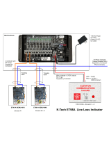
FIGURE 1.8 Main Relay Board (HC-RB4-VFAC)
5. HC-RB4-VFAC Main Relay Board - This board satisfies many of the code
requirements for relay contact redundancy and the requirements for normal terminal
stopping devices. It also provides the necessary circuitry for running the car on
Inspection or Access without the benefit of computers. Along with the HC-PCI/O board,
this board comprises the high voltage interface between the MC-PCA computer and the
individual car logic functions such as door operation, direction outputs, direction
sensing, main safety circuits, leveling circuitry, etc. This board typically contains 13 four-
pole relays as well as some terminals for field wiring. Test pads surround each relay for
/