Page is loading ...

Remote Automation Solutions
Form A6251
Part Number D301346X012
March 2021
LineGuard™ 2300 Program
User Manual (FloBoss 107)

LineGuard 2300 Program User Manual
ii Revised March-21
Contents
Chapter 1 – Introduction 1
1.1 Scope and Organization ................................................................................................................... 1
1.2 Product Overview ............................................................................................................................. 1
1.2.1 Basic Program Operation .................................................................................................... 2
1.3 Program Requirements .................................................................................................................... 6
1.3.1 License Key ......................................................................................................................... 6
Chapter 2 – Installation 7
2.1 Installing the License Key ................................................................................................................. 7
2.1.1 Installing a License .............................................................................................................. 7
2.2 Downloading the Program ................................................................................................................ 9
Chapter 3 – Configuration 13
3.1 LineGuard Status Screen ............................................................................................................... 14
3.1.1 LineGuard Status Screen – LineGuard Status tab ............................................................ 15
3.1.2 LineGuard Status – Log/Alarm Setup tab .......................................................................... 18
3.1.3 LineGuard Status – RoD Values tab ................................................................................. 21
3.2 LineGuard Valve Control Screen .................................................................................................... 22
3.2.1 LineGuard Valve Control – LineGuard Valve Control tab ................................................. 23
3.2.2 LineGuard Valve Control – Event Control tab ................................................................... 25
3.2.3 LineGuard Valve Control – Transmitter Fail tab ................................................................ 27
3.2.4 LineGuard Valve Control – Voltage Check tab.................................................................. 29
3.3 Saving the Configuration ................................................................................................................ 31
Chapter 4 – Reference Material 33
4.1 Point Type 22: LineGuard Pressure Log Configuration ................................................................. 34
4.2 Point Type 23: LineGuard Valve Control ........................................................................................ 38

LineGuard 2300 Program User Manual
Revised March-21 1
Chapter 1 – Introduction
This chapter describes the structure of this manual and presents an
overview and installation instructions of the LineGuard 2300 Program for
the FloBoss 107 (FB107).
1.1 Scope and Organization
This document serves as the user manual for the LineGuard
™
user
program for use in a FloBoss 107 (FB107). This manual describes how to
download, install, and configure the LineGuard user program (referred to
as the “LineGuard program” or “the program” throughout the rest of this
manual). You access and configure this program using ROCLINK™ 800
Configuration Software (version 2.60 or greater) loaded on a personal
computer (PC) running Windows
®
2000 (with Service Pack 2), Windows
XP (with Service Pack 3), Windows Vista (32-bit), or Windows 7 (32-bit).
The sections in this manual provide information in a sequence appropriate
for first-time users. Once you become familiar with the procedures and the
software, the manual becomes a reference tool.
This manual has the following major sections:
▪ Chapter 1 – Introduction
▪ Chapter 2 – Installation
▪ Chapter 3 – Configuration
▪ Chapter 4 – Reference
This manual assumes that you are familiar with the FB107 and its
configuration. For more information, refer to the following manuals:
▪ FloBoss 107 Flow Manager Instruction Manual (D301232X012)
▪ ROCLINK 800 Configuration Software User Manual (for FB107)
(D301249X012)
1.2 Product Overview
The LineGuard Electronic Linebreak Detection System is a self-contained
pipeline monitoring and line break detection device. The device is
intended to be installed at a pipeline valve site and is designated to provide
data acquisition and supervisory control (both locally and remotely) of a
single valve actuator.
The LineGuard product consists of standard FloBoss 107 Flow Manager
hardware and firmware while a user program provides the LineGuard
functionality. The program is responsible for pressure monitoring, data
logging and valve control. Custom user-defined displays are available for
configuring and monitoring the operation of the program.

LineGuard 2300 Program User Manual
2 Revised March-21
1.2.1 Basic Program Operation
This section briefly describes the operation of the LineGuard user program,
which monitors pipeline pressure, calculates the Rate of Pressure Drop
(RoD), maintains minor and major logs, and performs valve control.
Pipeline Pressure
Monitoring
The static pipeline pressure is sampled every 5 seconds and stored as Live
Pressure. This value is averaged over a configurable period called the
Average Sample Period and is stored as Average Pressure. The Average
Sample Period is user-configurable from 5 seconds to 60 seconds in 5
second intervals. The default Average Sample Period is 60 seconds (or 12
samples). The average pressure is averaged over a moving time window
and the time window is defined by the average sample period. The average
pressure is updated every 5 seconds. The average pressure is used to detect
major and minor line-break conditions. The average pressure is archived in
both major and minor data logs.
Rate of Drop (RoD)
Pressure Calculation
The LineGuard device reacts to a drop in pipeline pressure. The current
Rate of Pressure Drop (RoD) is calculated as the change in average
pressure over the last minute and is available every sample cycle (5
seconds) in units of pressure/minutes. The current RoD is rolled over to an
average RoD based on the average sample period. The average sample
period for RoD calculations is equal to the sample period used in
calculating average pressure. The average RoD is used to detect major and
minor line-break conditions. The average RoD is archived in both major
and minor data logs.
Data Logging
The LineGuard program maintains four data logs, major data logs, event
logs, and alarm logs.
Minor Data Logs
A Minor Log is initiated when a minor alarm is enabled and becomes
active. Alarm conditions include when the average pressure is less than the
minor low pressure setpoint, average pressure greater than the minor high
setpoint, and average RoD greater than the minor RoD setpoint. Each
minor log setpoint and alarm is user configurable.
A complete minor log consists of a beginning time stamp (MM/DD/YY
HH:MM:SS), 60 average pressure values and 60 average RoD values.
Values are stored in the log at a user configurable Minor Log Period. Valid
log periods for a minor log include 30 seconds, 1 minute, 2 minutes, 3
minutes, 4 minutes, and 5 minutes. At each log period the current average
pressure and average RoD is written to the minor log.
A minor log archives 60 (complete log) values for average pressure and
average RoD values regardless of whether the initiating alarm condition
persists. A log is archived to memory once the log is complete. Another
minor log is initiated if the minor log alarm condition remains active.
A total of 100 minor logs can be stored in the unit. Minor logs are circular
logs with the earliest log overwritten with the newest log once all 100 logs
are full. Minor log data archival will also stop 50 logs (60 values each)
after a major log alarm condition becomes active and will not resume until

LineGuard 2300 Program User Manual
Revised March-21 3
after the user has manually cleared the major log alarm state.
Major Data Logs
A Major Log is initiated when a major alarm becomes active, the alarm is
enabled, and the event duration period has been satisfied. Alarm conditions
include Average Pressure less than the Major Low SetPoint, Average
Pressure greater than Major High SetPoint, and Average RoD greater than
Major RoD SetPoint. Major Log SetPoints, alarms, and event durations are
user configurable.
A complete Major Log consists of a time stamp (MM/DD/YY
HH:MM:SS), 30 average pressure values, and 30 average RoD values prior
to the major alarm becoming active and 30 average pressure values and 30
average RoD values after the major alarm became active. The time stamp
indicates the actual time of the line break.
Only one major log is saved in the LineGuard unit. A major log will be
retained and not overwritten until you manually clear the major alarm state
by pressing Clear Logs on the LineGuard Status screen. Values are stored
in the log at a user configurable major log period. Valid log periods for a
major log include 5 seconds, 10 seconds, 15 seconds, and 30 seconds. The
current average pressure and average RoD is written to the major log at
each log period.
Event Logs
The program adds an entry to the Event log when changes in setpoints or
parameters occur that affect program operation. Changes can include
remote and local commands to change valve position, change setpoints,
and change in parameters that affect any aspect of the LineGuard
operation. The standard FloBoss firmware performs event logging. Event
data may be used to establish a history of LineGuard status and pipeline
valve activity. The circular event log maintains a maximum of 240 records
and overwrites old data as new events occur.
Alarm Logs
Alarm Logs are triggered by exceeding operating limits and setpoints. The
alarm log function is performed by the standard FloBoss firmware. The
alarm log collects, and stores data not directly related to operator change
requests. Alarm entries include battery low voltage condition and any other
input point high and low condition. The alarm log can store up to 240
alarms and overwrites old entries as new alarms are encountered.
An alarm entry is also created when a minor or major alarm becomes
active, a Minor or Major Alarm becomes inactive, and when automatic
valve closure is initiated, and a transmitter fail condition becomes active or
clears. The following user text type alarm is created by the calculation
program.

LineGuard 2300 Program User Manual
4 Revised March-21
Alarm Entry
Description
Auto Close Init
Indicates the time at which automatic valve closure was
initiated.
Major Low
Indicates the value and time at which the major low alarm
became active or inactive.
Major RoD
Indicates the value and time at which the major RoD alarm
became active or inactive.
Major High
Indicates the value and time at which the major high alarm
became active or inactive.
Minor Low
Indicates the value and time at which the minor low alarm
became active or inactive.
Minor RoD
Indicates the value and time at which the minor RoD alarm
became active or inactive
Minor High
Indicates the value and time at which the minor high alarm
became active or inactive.
Trans Low
Indicates the value and time at which the pressure value
reported from the transmitter dropped below the low limit.
Trans High
Indicates the value and time at which the pressure value
reported from the transmitter rose above the high limit.
Trans OK
Indicates the value and time at which the pressure value
reported from the transmitter are within alarm limits.
Shutdown Control
The LineGuard program automatically closes the valve when a major line
break is detected.
Line Break Detection
The Average Pressure and Average RoD are used to detect line-break
conditions every sample cycle (5 seconds). Valve closure is activated when
the four following conditions are met: a major log alarm becomes active, it
remains active for the configured Event Duration, auto-closure is enabled
for the event, and the Close Output field is defined. The major log will
continue to record data until it becomes full. The event duration can be
configured from 0 seconds to 1800 seconds (30 minutes).
If the average pressure or average RoD returns to an allowable level during
the event duration period, then valve closure is not initiated and normal
pressure monitoring resumes.
Once a line-break situation has been detected, valve closure is completed, a
major log is filled, and then all log recording and valve control stops. The
user must select Clear Logs on the LineGuard Status screen before normal
pressure monitoring, logging, and control is resumed. If the Open Output
field is defined, the user can open the valve by selecting Force Open on
the LineGuard Valve Control screen or remotely. If the Open Output field
on the LineGuard Valve Control screen is not defined, the user must
manually open the valve on site.

LineGuard 2300 Program User Manual
Revised March-21 5
Valve Control
The control valve can be opened and closed both remotely and on-site by
setting the “Manual Close Flag” or “Manual Open Flag.” When the
“Manual Open Flag” is set the configured “Open Output” is energized for
the “Open Duration.” When the “Manual Close Flag” is set the configured
“Close Output” is energized for the “Close Duration.” “Open Duration”
and “Close Duration” values can be configured from 5 seconds to 1800
seconds (30 minutes).
Automatic valve closure can be initiated by a high-pressure condition, low
pressure condition or a high rate of drop of pressure condition. After auto-
closure has been initiated, even a favorable pressure change will not de-
energize the “Close Output” and the valve will stroke to completion. Any
or all of these closure controls may be individually disabled if desired by
setting the “Auto-closure” for the alarm type to disabled. If auto-closure is
disabled, the program will still perform all other functions unless “Close
Output” is activated.
Limit switch inputs may be configured for both the open and close
operations. During valve closure the program will monitor the “Close Limit
Switch” status (if configured) and de-activate the “Close Output” when the
limit switch status becomes active. If the close limit switch input is not
defined, the close output will remain energized for the full close duration
period. During valve opening the program will monitor the “Open Limit
Switch” status (if configured) and de-activate the “Open Output” when the
limit switch status becomes active. If the open limit switch input is not
defined, the open output will remain energized for the full open duration
period.
Data Log Collection
Minor and major data logs are collected from the LineGuard unit using the
LineGuard Log Utility (refer to LineGuard Logs Utility User Manual
D301577X012). This software and associated documentation may be
purchased from Remote Automation Solutions. The interface software
allows the user to log-on into the LineGuard unit remotely or on-site and
retrieve logs. The utility is intended only for collection of minor and major
data logs from the LineGuard device. All other operations, including
program monitoring, program configuration, and event and alarm log
collection, are accomplished with the ROCLINK 800 configuration
software.
Input Error Detection
The program provides error detection for failed transmitters and input
power limits.
The user may enable a check for pressure transmitter fail detection (see tab
on the LineGuard Valve Control screen). The user enters low and high
pressure set points. When the transmitter fail check is enabled and the input
pressure is outside of one of the set points for more than a user defined
delay period, the program begins a transmitter reset sequence.
The program first cycles power to the pressure transmitter. If the pressure
value returns to within the set points, normal LineGuard operations are
continued. If the input pressure remains out of limits, the program initiates

LineGuard 2300 Program User Manual
6 Revised March-21
a restart (warm-start) of the FloBoss 107. If the pressure value returns to
within the set points, normal LineGuard operations are continued. If the
input pressure remains out of limits, line break detection software and
value closure algorithm are disabled until the pressure input value returns
to within the expected range.
The user may enable a check for input voltage error (see tab on the
LineGuard Valve Control screen). The user enters low and high input
voltage alarm limits. When the voltage check is enabled and the input
voltage to the FloBoss 107 is outside of one of the alarm limits, the
program first checks to see if a valve closure is already in progress. If a
closure is in progress, the program will wait for the closure to complete
before taking action. When the input voltage is out of limits and no closure
in is progress, line break detection software and value closure algorithm are
disabled until the input voltage returns to within limits.
1.3 Program Requirements
The LineGuard program is compatible with version 1.85 (or greater) of the
FB107 firmware and with version 2.60 (or greater) of the ROCLINK 800
software.
Program specifics include:
File Name
Target Unit/
Version
User Defined
Point (UDP)
Flash Used
(in bytes)
DRAM Used
(in bytes)
ROCLINK
800
Version
Display
Number
LineGuard_1-
1_13.bin
FB107 1.85
22, 23
16,338
16,282
2.60
21, 22
Note: You must connect a PC to the FB107’s LOI port before starting the
download.
For information on viewing the memory allocation of user programs, refer
to the ROCLINK 800 Configuration Software User Manual (for FB107)
(D301249X012).
1.3.1 License Key
Some applications require that you install a license in the CPU to run the
application. This license software is specific to these applications and is
the property of the individual vendor (shown in the Vendor Name field on
the License Key Administrator screens). RAS (and other authorized
vendors) distribute software licenses on security-enhanced universal serial
bus (USB) drives.
You must install the following license keys to use the LineGuard program.
▪ LineGuard License Key.

LineGuard 2300 Program User Manual
Revised March-21 7
Chapter 2 – Installation
This section provides instructions for installing the LineGuard program.
Read Section 1.3 of this manual for program requirements.
Note: The program and license key can be installed in any order. The
manual shows the installation of the license key first.
2.1 Installing the License Key
A USB key-based license is required to use the LineGuard program.
2.1.1 Installing a License
To install a USB key-based license on the FB107:
1. Insert the USB license key in a USB port on your PC.
2. Select Utilities > License Key Administrator > Transfer Between
DEVICE and KEY from the ROCLINK 800 menu bar. The Transfer
Licenses Between a Device and a Key screen displays.
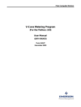
Figure 1. Transfer Licenses Between a Device and a Key

LineGuard 2300 Program User Manual
8 Revised March-21
Note: This screen has three sections. The upper portion (Licenses on
Device) shows any software licenses installed on the FB107. The
middle portion (Licenses on Key) shows software licenses on the
license key. The lower portion of the screen (License Key Event
Log) provides a rolling log of the last eight events related to this
license key.
3. Select the key-based license you want to transfer to the FB107
(LineGuard 2300, as shown in Figure 1).
4. Click Move to Device. ROCLINK moves the license from the key to
the FB107 and updates the screen.
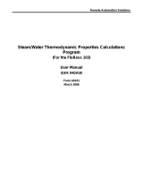
Figure 2. License Installed
Note: An FB107 can hold up to six different licenses, although you can
install only one instance of each license on the FB107. When you
click Move to Device, ROCLINK 800 moves only one instance of
the license onto the FB107 and automatically decreases the license
quantity on the USB key by one.
5. Verify the license name displays in the Licenses on Device section of
the screen. Proceed to Section 2.2 to download the user program.

LineGuard 2300 Program User Manual
Revised March-21 9
2.2 Downloading the Program
This section provides instructions for installing the program into the Flash
memory on the FB107.
To download the program using ROCLINK 800 software:
1. Connect the FB107 to your computer using the LOI port.
2. Start and logon to ROCLINK 800.
3. Select Utilities > User Program Administrator from the ROCLINK
menu bar. The User Program Administrator screen displays (see
Figure 3):
Figure 3. User Program Administrator
4. Click Browse in the Download User Program File frame. The Select
User Program File screen displays (see Figure 4).
5. Select the path and user program file to download from the CD-ROM.
(Program files are typically located in the Program Files folder on the
CD-ROM). As Figure 4 shows, the screen lists all valid user program
files with the .BIN extension:

LineGuard 2300 Program User Manual
10 Revised March-21
Figure 4. Select User Program File
6. Click Open to select the program file. The User Program
Administrator screen displays. As shown in Figure 5, note that the
Download User Program File frame identifies the selected program
and that the Download & Start button is active:
Figure 5. User Program Administrator

LineGuard 2300 Program User Manual
Revised March-21 11
7. Click Download & Start to begin loading the selected programs. The
following message displays:
Figure 6. Confirm Download
8. Click Yes to begin the download. When the download completes the
following message displays:
Figure 7. ROCLINK 800 Download Confirmation
9. Click OK. The User Program Administrator screen displays (see
Figure 8). Note that:
▪ The User Programs Installed in Device frame identifies the
installed program(s).
▪ The Status field indicates that the program is running.

LineGuard 2300 Program User Manual
12 Revised March-21
Figure 8. User Program Administrator
Note: If you install the program before you install the license key, the
Status field reads License Not Found. Install the license key to
change the status of the program.
10. Click Close. The ROCLINK 800 screen displays and the download is
complete. Proceed to Chapter 3, Configuration.

LineGuard 2300 Program User Manual
Revised March-21 13
Chapter 3 – Configuration
After you have loaded the LineGuard user-program on the FB107, you
configure the program using two program-specific screens (LineGuard
Status and LineGuard Valve Control):
▪ Use the LineGuard Status screen to view program settings and
configure alarms, the sample period, and the units of measurement
used by the program.
▪ Use the LineGuard Valve Control screen to configure parameters for
valve opening and closing and to configure the actions taken by the
program when a failed transmitter is encountered or input voltage is
out of limits.
To configure the program (after logging onto ROCLINK 800 and
successfully installing the program and license key), proceed through the
program screens as shown in this section.
You can access all the program-specific screens from the main ROCLINK
800 screen:
Figure 9. ROCLINK 800

LineGuard 2300 Program User Manual
14 Revised March-21
3.1 LineGuard Status Screen
Use this screen to view the status and parameter settings of the LineGuard
program and set the pressure inputs used by the program. You also
configure alarm parameters including alarm settings, alarm setpoints,
alarm log periods, and the average sample period.
To access this screen:
1. From the Directory Tree, select User Program > LineGuard User
Prgm.
2. Double-click Display #21 LineGuard Status. The LineGuard Status
screen displays:
Figure 10. LineGuard Status
Note: The LineGuard Status screen—like the other LineGuard Valve
Control screen—has a tab format. Sections 3.1.1, 3.1.2, and 3.1.3
discuss the requirements for each tab on the LineGuard Status
screen.

LineGuard 2300 Program User Manual
Revised March-21 15
3.1.1 LineGuard Status Screen – LineGuard Status tab
Use this screen (which displays when you access the LineGuard Status
screen) to view the status and parameter settings of the LineGuard
program.
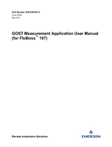
Figure 11. LineGuard Status, LineGuard Status tab
1. Review the values in the following fields:
Field
Description
Program Status
This read-only field displays the current
condition of the user program. Valid values
are Running - No error, Running - Shutting
down, Not running - No program loaded,
Not running - Program not enabled, Not
running - Library version error, Not
running - No license found, and Not
running - License expired.
Average Sample Period
This read-only field displays, in seconds, the
period over which input pressure and Rate of
Drop are averaged. Valid values include 5, 10,
15, 20, 25, 30, 35, 40, 45, 50, 55, and 60
seconds.
Transmitter Status
This read-only field displays the current

LineGuard 2300 Program User Manual
16 Revised March-21
Field
Description
transmitter status. Valid values are Good –
Normal Operation, Failed – Low Pressure,
and Failed – High Pressure.
Live Pressure
This read-only field displays the current (live)
value from pressure input. This value is
updated every five seconds.
Average Pressure
This read-only field displays the average
pressure over the last average sample period.
This value is updated every five seconds.
Current RoD
This read-only field displays the current Rate
of Pressure Drop (RoD). The RoD is the
average pressure one minute ago minus the
current average pressure in units of
pressure/minute. This value is updated every
five seconds.
Average RoD
This read-only field displays the last
calculated average of Rate of Pressure Drop
(RoD) over the last average sample period.
This value is used to determine the state of
major and minor RoD alarms. This value is
updated every five seconds.
Major Low Alarm
This read-only field displays the current
setting (Enabled/Disabled), threshold
(SetPoint), and current state (Status) of the
Major Low Alarm. An average pressure below
the indicated threshold activates an alarm,
initiates a major log, and starts valve control if
the Major Low Alarm is Enabled. If disabled,
this alarm is ignored.
Major High Alarm
This read-only field displays the current
setting (Enabled/Disabled), threshold
(SetPoint), and current state (Status) of the
Major High Alarm. An average pressure
above the indicated threshold activates an
alarm, initiates a major log, and starts valve
control if the Major High Alarm is enabled. If
disabled, this alarm is ignored.
Major RoD Alarm
This read-only field displays the current
setting (Enabled/Disabled), threshold
(SetPoint), and current state (Status) of the
Major RoD Alarm. An average RoD above the
indicated threshold activates an alarm,
initiates a major log, and starts valve control if
the Major RoD Alarm is enabled. If disabled,
this alarm is ignored.
Minor Low Alarm
This read-only field displays the current
setting (Enabled/Disabled), threshold
(SetPoint), and current state (Status) of the
Minor Low Alarm. An average pressure below
the indicated threshold activates the alarm
and a minor log is initiated. If disabled, this

LineGuard 2300 Program User Manual
Revised March-21 17
Field
Description
alarm is ignored.
Minor High Alarm
This read-only field displays the current
setting (Enabled/Disabled), threshold
(SetPoint), and current state (Status) of the
Minor High Alarm. An average pressure
above the indicated threshold activates the
alarm and a minor log is initiated. If disabled,
this alarm is ignored.
Minor RoD Alarm
This read-only field displays the current
setting (Enabled/Disabled), threshold
(SetPoint), and current state (Status) of the
Minor RoD Alarm. An average RoD above the
indicated threshold activates the alarm and a
minor log is initiated. If disabled, this alarm is
ignored.
Major Log Period
This read-only field displays, in seconds, the
period at which pressure and RoD values are
placed in the major log. Valid periods are 5,
10, 15, and 30 seconds.
Major Log State
This read-only field displays the current state
of the major log function. Valid values are Not
Logging, Actively Logging, and Log is
Complete.
Number Major Logs
This read-only field displays the number of
major logs archived.
Note: This number is always 0 or 1.
Minor Log Period
This read-only field displays, in seconds, the
period at which pressure and RoD values are
placed in the minor log. Valid values are 30,
60, 120, 180, 240, and 300 seconds.
Minor Log State
This read-only field displays the current state
of the minor log function. Valid values are Not
Logging, Actively Logging, and Log is
Complete.
Number Minor Logs
This read-only field displays the number of
minor logs archived.
Note: The maximum number of minor logs is
100.
Minor Log Index
This read-only field displays the minor log
index points to the most recent minor log in
the system. Up to 100 minor logs are
maintained in the LineGuard database.
Event Duration
This read-only field displays, in seconds, the
configured period in which a major log alarm
must be active before major log archival and
valve closure initiates.
Active Event Time
This read-only field displays, in seconds, the
length of time a major alarm has been active.

LineGuard 2300 Program User Manual
18 Revised March-21
Field
Description
Reset/Clear Logs
Clicking this button clears all major and minor
logs from the database and sets the log status
to Not Active. The records of the highest RoD
values are also cleared.
2. Click Apply to save any changes you have made to this screen.
3. Click Close to return to the ROCLINK 800 screen. Proceed to Section
3.1.2 to configure the Log/Alarm Setup screen.
3.1.2 LineGuard Status – Log/Alarm Setup tab
Use this screen to configure the pressure input and the pressure units used
by the program. You also use this screen to configure alarm parameters
including alarm settings, alarm setpoints, alarm log periods, and the
average sample period.
To access this screen:
1. Select the Log/Alarm Setup tab on the LineGuard Status screen.
Figure 12. LineGuard Status, Log/Alarm Setup tab
/