Page is loading ...

Remote Automation Solutions
Part D301754X012
April 2021
Linear Meter Flow Calculation Program
User Manual (for FloBoss™ 107)

Linear Meter Flow Calculation Program User Manual
ii Revised April-21
Contents
Chapter 1 – Introduction 1
1.1 Scope and Organization...................................................................................................................... 1
1.2 Product Overview ................................................................................................................................ 1
1.3 Program Requirements ....................................................................................................................... 3
Chapter 2 – Installation 5
2.1 Downloading the Program .................................................................................................................. 5
Chapter 3 – Configuration 1
3.1 Linear Meter Setup Screen ................................................................................................................. 2
3.1.1 Linear Meter Setup Screen – General Tab ............................................................................ 4
3.1.2 Linear Meter Setup Screen – Inputs Tab ............................................................................... 8
3.1.3 Linear Meter Setup Screen – Advanced Tab ....................................................................... 11
3.1.4 Linear Meter Setup Screen – Fluid Properties Tab ............................................................. 14
3.1.5 Linear Meter Setup Screen – Sampler Tab ......................................................................... 17
3.1.6 Linear Meter Setup Screen – Calibration Factors Tab ........................................................ 19
3.1.7 Linear Meter Setup Screen – Alarms Tab ........................................................................... 21
3.2 Linear Meter Values Screen ............................................................................................................. 24
3.2.1 Linear Meter Values –Values Tab ........................................................................................ 26
3.2.2 Linear Meter Values Screen – Calculated Factors Tab ....................................................... 28
3.3 Saving the Configuration ................................................................................................................... 30
Chapter 4 – Reference 32
4.1 Calculation Details ............................................................................................................................ 32
4.2 Point Type 31: Linear Meter Setup ................................................................................................... 34
4.3 Point Type 32: Linear Meter Values .................................................................................................. 36

Linear Meter Flow Calculation Program User Manual
Revised April-21 iii
[This page is intentionally left blank.]

Linear Meter Flow Calculation Program User Manual
Revised April-21 1
Chapter 1 – Introduction
1.1 Scope and Organization
This document serves as the user manual for the Linear Meter Flow
Calculation User Program (QER 08Q026) for use in a FloBoss™ 107
(FB107). This manual describes how to download and configure the
program (referred to as the “Linear Meter program” or “the program”
throughout the rest of this manual). You access and configure this program
using ROCLINK™ 800 Configuration Software (version 2.60 or greater)
loaded on an personal computer running Windows® 2000 (with Service
Pack 2), Windows XP (with Service Pack 3), or Windows Vista™ (32-
bit), or Windows 7 (32-bit and 64-bit).
The sections in this manual provide information appropriate for first-time
users. Once you become familiar with the procedures and the software
running in a FB107, the manual becomes a reference tool.
This manual has the following major sections:
▪ Chapter 1 – Introduction
▪ Chapter 2 – Installation
▪ Chapter 3 – Configuration
▪ Chapter 4 – Reference
This manual assumes that you are familiar with the FB107 and its
configuration. For more information, refer to the following manuals:
▪ FloBoss 107 Flow Manager Instruction Manual (part
D301232X012)
▪ ROCLINK 800 Configuration Software User Manual (for FB107)
(part D301249X012)
1.2 Product Overview
The Linear Meter program allows a FB107 to interface with meters whose
flow input is proportional to either the mass flow or the uncorrected
volumetric flow. Meter types with flow input proportional to the
uncorrected volumetric flow includes turbine, vortex, ultrasonic, and
positive displacement meters. While meter types with flow input
proportional to the mass flow include Coriolis meters. Volume, mass flow
rates, and totals are calculated and stored for both volumetric and mass
meters. The program uses the corresponding meter run point in the
FB107’s firmware to store Linear Meter calculated values and
accumulations. Additional configuration parameters are in the program’s
user-defined point types.

Linear Meter Flow Calculation Program User Manual
2 Revised April-21
For natural gas measurement with turbine meter (per AGA Report #7 2006
edition), the Linear Meter program is NOT required, as this functionality
for a volume type turbine meter for natural gas measurement is built into
the FB107 firmware. However, the program does provide an additional
implementation of this calculation and can be used in place of the
firmware.
You enable the Linear Meter calculation for meter runs with Linear Meter
hardware installed. With the calculation enabled, the FB107 bypasses the
standard meter run flow calculations and performs the Linear Meter
calculation instead. All standard meter run parameters, as well as the
additional Linear Meter parameters, are available for assignment to
Modbus registers, PID control loops, historical archiving, and FST
functions.
The program is designed to integrate with the properties calculation
included in the FB107 Firmware (AGA Report #8, 1992 edition for natural
gas and other related hydrocarbons), or other fluids whose properties are
provided by a separate user program installed in the FB107 (such as water
and steam). The only fluid properties used by the Linear Meter program
are the flowing and base densities. When correcting from volume at
flowing conditions to volume at base conditions, the ratio of the flowing
density to the base density is used.
When a meter type of mass (Coriolis) is used, the program provides the
ability to correct for the effect of pressure on the mass flowrate and
accumulation. This feature is used for enhanced accuracy in high pressure
Coriolis applications. This correction can be applied inside the Coriolis
device itself, or within the FB107 Linear Meter program. However, it is
common to apply this correction in the FB107, as it is likely to contain the
live value from a pressure transmitter.
When used in conjunction with the FB107 Micro Motion Coriolis
Interface Module, the program provides integration between the raw
Coriolis data (without the use of pulses) and the FB107 meter runs. Linear
Meter program accumulations are determined by detecting the incremental
increases in the Coriolis Interface Module accumulator and adding that to
the totals. Conversions between volume and mass units are handled
automatically when the Coriolis Interface Module is used.

Linear Meter Flow Calculation Program User Manual
Revised April-21 3
1.3 Program Requirements
You download the Linear Meter program to—and then run it from—the
Flash and RAM memory on the FloBoss 107 with firmware version 1.40
(or greater). Download and configure the program using the ROCLINK 800
Configuration software version 2.60 (or greater).
Notes:
▪ Two versions of the program for QER 08Q026 are included.
Installation and operation are identical between the two programs, but
they use different point type locations, different display numbers, and
are loaded into different program slots on the FB107.
LinearMeter_5.bin loads into user program location 5 and User
Defined Points (UDP) 31 and 32. LinearMeter_6.bin loads into user
program location 6 and User Defined Points (UDP) 33 and 34. Install
the program version that avoids point type conflicts with currently
installed programs.
▪ This document shows the installation of LinearMeter_5.bin. The
installation process and functionality are the same for all version of the
Linear Meter Flow Calculation Program.
The downloadable program is:
File Name
Target Unit/
Version
User Defined
Point (UDP)
Flash Used
(in bytes)
DRAM Used
(in bytes)
ROCKLINK 800
Version
Display
Number
LinearMeter_5-1_05.bin
1.05
31, 32
13293
16,384
2.60
32, 33
LinearMeter_6-1_05.bin
1.05
33, 34
13293
16,384
2.60
34, 35
Note: You must connect a PC to the FloBoss’s LOI port before starting
the download.
For information on viewing the memory allocation of user programs, refer
to the ROCLINK 800 Configuration Software User Manual (for FB107)
(part D301249X012).

Linear Meter Flow Calculation Program User Manual
4 Revised April-21
[This page is intentionally left blank.]

Linear Meter Flow Calculation Program User Manual
Revised April-21 5
Chapter 2 – Installation
This section provides instructions for installing the Linear Meter program
into the FB107. Read Section 1.3 of this manual for program requirements.
2.1 Downloading the Program
This section provides instructions for installing the user program into
FloBoss memory.
Note: Connect a PC to the FloBoss’s LOI port before starting the
download.
To download the user program:
1. Start and logon to ROCLINK 800.
2. Select ROC > Direct Connect to connect to the FloBoss unit.
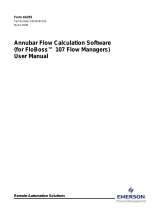
3. Select Utilities > User Program Administrator from the ROCLINK
menu bar. The User Program Administrator screen displays
(see Figure 1):
Figure 1. User Program Administrator
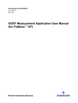
4. Click Browse in the Download User Program File frame. The Select
User Program File screen displays (see Figure 2).
5. Select the path and user program file to download from the CD-ROM.
(Program files are typically located in the Program Files folder on the

Linear Meter Flow Calculation Program User Manual
6 Revised April-21
CD-ROM). As Figure 2 shows, the screen lists all valid user program
files with the .BIN extension:
Figure 2. Select User Program File
6. Click Open to select the program file. The User Program
Administrator screen displays. As shown in Figure 3, note that the
Download User Program File frame identifies the selected program
and that the Download & Start button is active:
Figure 3. User Program Administrator

Linear Meter Flow Calculation Program User Manual
Revised April-21 7
7. Click Download & Start to begin loading the selected programs. The
following message displays:
Figure 4. Confirm Download
Note: For the FB107, ROCLINK800 assigns program positions based
on memory allocations. For this reason, the LinearMeter_5.bin
program automatically installs as program 5. For
LinearMeter_6.bin program automatically installs as program
6.
8. Click Yes to begin the download. During the download, the program
performs a warm start, creates an event in the event log, and—when
the download completes—displays the following message:
Figure 5. ROCLINK 800 Download Confirmation
9. Click OK. The User Program Administrator screen displays (see
Figure 6). Note that:
▪ The User Programs Installed in Device frame identifies the loaded
program.
▪ The Status field indicates that the program is running.

Linear Meter Flow Calculation Program User Manual
8 Revised April-21
Figure 6. User Program Administrator
10. Click Close and proceed to Chapter 3 to configure the program.

Linear Meter Flow Calculation Program User Manual
Revised April-21 1
Chapter 3 – Configuration
After you have downloaded and started the Linear Meter program, you
configure the program and view calculation results using the ROCLINK
800 software. To do this, you use two program-specific screens (Linear
Meter Setup and Linear Meter Values):
▪ Use the Linear Meter Setup screen to set the parameters for the meter
run.
▪ Use the Linear Meter Values screen to view results from the Linear
Meter calculations.
Note: Configure history points after you configure the Linear Meter
program. To configure history points, refer to Table 7-2. EFM
History Points (AGA 7) in Section 10.2 of the ROCLINK800
Configuration Software User Manual (for FloBoss 107),
(part D301249X012).
Figure 7. ROCLINK 800

Linear Meter Flow Calculation Program User Manual
2 Revised April-21
3.1 Linear Meter Setup Screen
Once you have successfully loaded the Linear Meter program into the
FloBoss, you can access the Linear Meter Setup screen and configure the
meter runs.
To access this screen:
1. Click User Program > Linear Meter > Display #32, Linear Meter
Setup from the ROCLINK configuration tree:
2. Double-click #1, Meter #1. The Linear Meter screen displays
(see Figure 8):
Figure 8. Linear Meter Setup
Note: Six fields at the top of the screen (Point number, Program Status,
Meter Tag, Meter Description, Active Calculations – Flow, and
Active Calculations – Fluid Props) appear on all tabs.

Linear Meter Flow Calculation Program User Manual
Revised April-21 3
3. Review and change as necessary the values in the following fields:
Field
Description
Point Number
Selects the meter run to configure. Click to
display all defined instances. Clicking a different
meter run causes the screen to display the
values for that meter run.
Program Status
This read-only field shows the current state of
the user program. Valid values are: Program Not
Loaded, Program Loaded – Not Started,
Program Running, Program Shutting Down,
and Not Running – Library Version Error.
Meter Tag
Sets the unique identifier for the selected meter.
Meter Description
Sets the description of the selected meter.
Flow
This read-only field shows the flow calculation
standard currently performing flow calculations
for the selected meter run.
Fluid Props
This read-only field shows the properties
calculation standard currently performing
properties calculations for the selected meter run.
4. Click Apply to save your changes, and proceed to Section 3.1.1 to
configure the General tab.

Linear Meter Flow Calculation Program User Manual
4 Revised April-21
3.1.1 Linear Meter Setup Screen – General Tab
Use the General tab (which displays when you access the Linear Meter
Setup screen) to enable the Linear Meter calculation, specify the averaging
technique used by the program, and define program-specific options.
Figure 9. Linear Meter, General Tab
1. Review and change as necessary the values in the following fields:
Field
Description
Linear Meter
Enables or disables the Linear Meter program to
perform the flow calculations for the selected
meter run. Valid selections are Enabled or
Disabled.
Meter Type
Sets the type of meter associated with the meter
run. Valid selections are Volume (volume
metering device such as a turbine meter) or
Mass (Micro Motion Coriolis Mass Meter or
similar mass meter).
Note: This field displays only if you select
Enabled for the Linear Meter option.
Units for Heating
Value, Alarms, and
Sampler
Sets the type of units used for heating value,
alarms, and sampler of the meter run. Valid
selections are Volume, (units are BTU/CF or
MJ/M3, Ft
3
or M3, etc) and Mass (units are
BTU/Lb or MJ/Kg, Lb or Kg, etc).

Linear Meter Flow Calculation Program User Manual
Revised April-21 5
Field
Description
Flow Alarming
Enables or disables flow alarming for the meter.
If enabled, alarm status changes are added to
the Alarm Log. Use the Alarms tab to configure
the alarms. If disabled, no alarm generates for
this meter, regardless of the alarm
configuration.
Base Multiplier Value
(BMV) Integral
Multiplier Value (IMV)
Sets, in minutes, how frequently the system
recalculates the fluid properties and resulting
Base Multiplier Value (BMV) (per the API
measurement standard Chapter 21, Section 1).
If the flow calculation for the meter run is AGA3-
92, ISO5167-2003, or another calculation
standard where the flow input is a differential
pressure, this field is labeled Integral Multiplier
Value (IMV).
Averaging Technique
Sets the averaging technique for determining
the average static pressure and flowing
temperature during each BMV/IMV for the meter
run. If the flow input is from a differential
pressure meter, the average differential
pressure is also determined. For further details,
see API measurement standard Chapter 21,
Section 1, Appendix B. Valid selections are:
Flow
Dependant
Linear
Calculates the average static
pressure and average flowing
temperature with equal weighting
given to each sample when there
is flow through the meter. For
samples in which there is no flow,
the value is not included in the
average. However, if there is no
flow during the BMV/IMV, the
system determines averages
using all of the samples.

Linear Meter Flow Calculation Program User Manual
6 Revised April-21
Field
Description
Flow
Dependant
Formulaic
Calculates averages for the static
pressure and flowing temperature
where each sample is raised to
the power to which the parameter
is raised in the flow equation, with
equal weighting given to each
sample when there is flow
through meter. For samples
where there is no flow, the value
is not included in the averaging.
However, if there is no flow during
the BMV/IMV, averages are
determined using all of the
samples. At the end of the
BMV/IMV, the resulting average is
raised to the reciprocal of the
power to which the value is raised
in the flow equation.
Note: Flow Dependent Linear
and Flow Dependent
Formulaic averaging yield
the same result when used
with linear meters.
Flow
Weighted
Linear
Calculates averages for the static
pressure and flowing temperature
with weighting for a sample being
the ratio of the flow through the
meter at the time of the sample to
the total flow during the BMV/IMV.
For samples where there is no
flow, the value is not included in
the average. However, if there is
no flow during the BMV/IMV,
averages are determined using all
of the samples.

Linear Meter Flow Calculation Program User Manual
Revised April-21 7
Field
Description
Flow
Weighted
Formulaic
Calculates averages for the static
pressure and flowing temperature
where each sample is raised to
the power to which the parameter
is raised in the flow equation, with
weighting for a sample being the
ratio of the flow at the time of the
sample to the total flow during the
BMV/IMV. For samples where
there is no flow, the value is not
included in the average. However,
if there is no flow during the
BMV/IMV, averages are
determined using all of the
samples. At the end of the
BMV/IMV, the resulting average is
raised to the reciprocal of the
power to which the value is raised
in the flow equation. With a linear
meter, flow weighted formulaic
averaging yields the same result
as flow weighted linear averaging.
Note: Flow Weighted Linear and
Flow Weighted Formulaic
averaging yield the same
result when used with
linear meters.
Active Flow Alarms
This display-only field shows any alarm
currently active. For example, Low indicates
that the calculated flow is below the Low Alarm
limit. Other alarms can include High, No Flow,
and Manual Mode.
2. Click Apply to save any changes, and proceed to Section 3.1.2 to
configure the Inputs tab.

Linear Meter Flow Calculation Program User Manual
8 Revised April-21
3.1.2 Linear Meter Setup Screen – Inputs Tab
Use the Inputs tab to define the inputs used by the Linear Meter
calculation.
To access this screen:
1. Select the Inputs tab on the Linear Meter Setup screen. One of the
following four screens displays:
Note: This tab displays only if you select Enabled for Linear Meters
on the General tab.
Figure 10(a). Linear Meter Setup, Inputs tab
(Meter Type is Volume, I/O Definition is a PI Point)
Figure 10(b). Linear Meter Setup, Inputs tab
(Meter Type is Volume, I/O Definition is an Analog Value)
Figure 10(c). Linear Meter Setup, Inputs tab
(Meter Type is Mass, I/O Definition is a PI Point)
Figure 10(d). Linear Meter Setup, Inputs tab
(Meter Type is Mass, I/O Definition is an Analog Value)

Linear Meter Flow Calculation Program User Manual
Revised April-21 9
2. Review and change as necessary the values in the following fields:
Field
Description
Uncorrected Volume
Sets the parameter for the uncorrected volume
flow rate from the meter. Click to display the
Select TLP dialog box you use to assign the
parameter. The units for the uncorrected volume
value are MCF/Day or kM
3
/Day.
If the parameter for the uncorrected volume flow
rate is from a PI point, select parameter 13
(EU). If the parameter for the uncorrected
volume flow rate is an analog value, select that
parameter.
Note: This field displays only if the meter type
is volume.
Mass
Sets the parameter for the mass flow rate from
the meter. Click to display the Select TLP
dialog box you use to assign the parameter. The
units of the mass are Mlb/Day or Tonnes/Day.
If the parameter for the mass flow rate is from a
PI point, select parameter 13 (EU). If the
parameter for the mass is an analog value,
select that parameter.
Note:
▪ This field displays only if the meter type
is mass (Coriolis).
▪ When the program is used with the
Micro Motion Coriolis Interface Module,
this should be set to the module's
forward mass flow rate, parameter 11
(Mass Flow Rate Fwd" of point type 65.
Static Pressure
Sets the parameter for the static pressure. Click
to display the Select TLP dialog box you use to
assign the parameter. The units for the static
pressure are PSIG/PSIA or kPa(g)/kPa(a).
Temperature
Sets the parameter for the flowing temperature
of the fluid. Click to display the Select TLP
dialog box you use to assign the parameter. The
units for the flowing temperature are Deg F or
Deg C.
Accumulator
Sets the parameter for an accumulator
containing the current amount of flow measured
by the meter. It is assumed that this parameter
rolls over at 1,000,000.0 and is in the
appropriate units. When the program is used in
conjunction with the Micro Motion Coriolis
Interface Module, this should be set to the
module’s ongoing mass accumulator, parameter
171 (Mass Accumulated) of point type 65. The
program will automatically convert the mass to
the required units in this case.
/