Page is loading ...

Type Dosaodor-D
www.emersonprocess.com/regulators
O.M.T .
User Manual
November 2009
D103117X012
TYPE DOSAODOR-D SOFTWARE FOR CONFIGURATION OF
TYPE DOSAODOR-D ODORANT INJECTION SYSTEM
Figure 1. ROCLINK 800 Odorizer System Software

2
Type Dosaodor-D
INDEX: General Overview
5 General Description
Equipment Description
6 Objective
Introduction
7 Version Requirements for ROC800 Hardware and ROCLINK800 Software
Minimum Software and Hardware Requirements
Installing License Key
Program Installation
8 Program Startup
9 Program Work Area
10 ROC809 Controller Programming
11 ROC809ControllerConguration
Connecting to the ROC809
Type Dosaodor–D Interface
Startup Procedure and Compilation of Work Parameters
System Conguration
13 Location Information
14 Flow Rate Input
Injection System
Supply Tank Input
Pulse Flow Rate Input
15 Analog Flow Rate Input
Analog Supply Tank Level Input
InjectionDataConguration
16 OdorantDataConguration
17 OperatingDataConguration
Output Data
I/O Cards
Alarm Conguration
18 Location Information
Alarm Output Contact Selection
19 Flow Rate Alarm
20 Odorant Calibration Cylinder Fill Alarm
Flow Computer Alarm
Low Flow Alarm
High Flow Alarm
Alarm Restart Options
Injector Warnings
Alarms and Warnings
22 Alarms
23 Last Alarm
Warning
Last Warning
Alarm Contact Status
Alarm Log File
24 Events Log File

3
Type Dosaodor-D
INDEX: Maintenance
Maintenance Data
26 System Information
System Data
Program Status
Data Accumulators
Current Injector Data
27 ROC809 Date/Time
Wash Cycle
28 Injector Flush
Current Odorant Calibration Cylinder I/O
Process Digital Inputs
Process Digital Output
Operation
Current Information
30 Location Information
Current Injector Data
Current (Odorant Calibration Cylinder) I/O Status
Alarms – Warnings – Last Alarm
ROC809 Date/Time
31 Flow Data
Odorant Calibration Cylinder Volume Data
Odorant Calibration Cylinder Fill Data
Odorant Data
32 Update of Flow Data and Odorant Data Accumulators
Current Mode
Disabled Mode
33 Auto Mode
Manual Mode
34 Minimum Rate Mode
35 RellMode
Purge/Wash Mode
Operating Data
37 Location Information
Current Injector Data
38 Odorant Calibration Cylinder Fill Data
Odorant Calibration Cylinder Volume Data
OperatingDataConguration
InjectionDataConguration
OdorantDataConguration
ROC809 Date/Time
39 Current Flow Data
Current Odorant Data

4
Type Dosaodor-D
INDEX: Hardware Conguration
39 ROC809HardwareConguration
40 Physical I/O
41 Data History
42 Reports
Alarm Callouts
Parameters
Modbus
44 Host Modbus
48 ROC800 Modbus Data Conversion

5
Type Dosaodor-D
General Overview
General Description
The Type Dosaodor-D is a computerized natural gas odorization system that injects odorant proportional to the
owrateofthegasintransit.Thesystemoperatesbyliquid-injectionandcanbeinstalledincombinationwith
traditional absorption-type devices.
Themicroprocessorbasedcontrolsystemisoperatorcongurableandcanbeinterfacedwithremotemonitoring
and control systems. The ability to collect historical data regarding gas volumes, amounts of injected odorant and
the relative concentration provides facility managers with objective aids to verify proper system operation.
The control system maintains the desired odorant concentration level by varying the odorant injection rate in
proportiontothegasowrateofthestation,evenwhentherearesignicantvariationsintheowrate.This
particular feature provides a marked increase in safety regarding the distribution of natural gas for public use. By
maintainingaconstantlevelofodorantconcentrationinthegasow,anyleakageofgascanbeidentied,thereby
decreasing the possibility of accidents.
Theconcentrationratioisensuredbythemicroprocessorbasedcontrolunitwhichreceivesitsowinputaseither
adigitalpulsecountervolumesignalfromaowcomputer/volumetriccounterorfroma4-20mAanalogsignal.
Thecontrolunitcomparestheowwiththeconcentrationleveltobemaintainedandcalculatesthecorrect
electronic signals to be transmitted to the injection device.
The electronic control unit uses a special odorant calibration cylinder to measure of the liquid that has been injected
and calculates any adjustments to be made in the injection rate, thereby ensuring a marked level of reliability and
overall precision of the system. This method allows the system to be self-monitoring and self-correcting.
During routine operation, in the versions that include two injection devices, the software provides the exchange
from one injector to the other to ensure that the same device does not always remain idle. One injector is
stopped and used as a back-up for the other.
A procedure has been designed to decontaminate the entire injection system in the unusual event of system
maintenance. This Purge/Wash procedure is under the direct control of the maintenance technician using the
ROCLINK800congurationsoftware.
The pneumatic portion of the system operates using differential pressure created between the upstream and
downstream sections of a gas reducing and metering station, or a gas compressor unit (minimum 14.5 psi / 1 bar
above injection point pressure).
The high-pressure upstream gas is used as the pneumatic driving force in order to inject the odorizing liquid into
the downstream pipeline.
Thesystemdoesnotusedosingpumpsorothercomplexdevicesforthemeasurementofodorantowrates.
Thesedevicesstillrequireperiodicalmaintenance,whichisaparticularlydifcultprocedurewithpartsthathave
come into contact with the odorizing liquid.
The Type Dosaodor-D is designed to accomplish these overall objectives:
• Operationalsafety
• Extremereliability
• Lowmaintenance
• Easytouse
• Reliabilityoftheresults-Consistentodorizationthroughoutowrange
Equipment Description
The primary equipment consists of an electrically controlled injection panel installed in the hazardous area and
interconnected by electrical cabling to a control system using the Type ROC809 Remote Operations Controller installed
in the safe area.

6
Type Dosaodor-D
Theinjectionpanelwillbedesignedandcertied,inaccordancewithinternationalstandards,forinstallationinareas
with a risk of explosion.
Theentireinjectionpanelismadeofstainlesssteelanddoesnothaveapaintednishorscreenprintingdueto
the aggressive nature of odorizing liquids.
The control system supplies the proper power and control signals to the injection panel and, if required, must
contain the safety barriers needed to comply with system installations requiring intrinsic safety.
The Type ROC809 based control system must be installed in a safe area and operates using 12 Vdc power
supplied by either an AC to DC power supply or any adequate 12 Vdc power source with battery backup.
In the event of a power outage, the controller saves the programming data, by means of an on-board battery, and
sends a signal to activate any emergency devices (it normally restarts operation of an absorption type backup system).
Objective
The objective of this document is to provide the operator with the necessary information to operate the user
interface(alsodenedasHMI:Human-MachineInterface).
Figure 2. Type ROC809 Remote Telemetry Unit Figure 3. Type Dosaodor-D Pneumatic Panel

7
Type Dosaodor-D
Introduction
ROCLINK 800 Configuration Software, a Windows
®
based program, enables complete configuration, whether
local or remote, of the Type Dosaodor-D odorant system, measurement of data in real time, management of
historical data, and control of alarm events. Connection is via serial port, ethernet port, or modem.
ROCLINK 800 software has an easy-to-use Windows interface. The Configuration Tree navigation interface
makes accessing features quick and easy.
Drop-down menus simplify access to the software functions. Dialog boxes and drop-down list boxes facilitate
direct selections and data entry. Actions can be performed with the keyboard or a mouse.
ThemainspecicationsoftheROCLINK800softwareareasfollows:
MS Windows interface•
Singlecongurationpointforeachpartoftheequipment•
Completecongurationforeachpartoftheequipment•
Periodic consultation of real time data, historical data, and alarms•
Display of real time data, historical data, and alarms•
Archiving of historical data in relational database•
Version Requirements for ROC800 Hardware and ROCLINK 800 Software
• ROC800 Version 2.02 or later
• ROCLINK800Version1.74orlater
Minimum Software and Hardware Requirements
Pentium•
®
-class processor (233 MHz or greater recommended)
CD-ROM drive•
Windows 98, ME, NT 4.0 (Service Pack 6), 2000 (Service Pack 2), or XP•
64 MB of RAM (Random Access Memory)•
SVGA color monitor, 800 x 600 pixels, small fonts•
15 to 75 MB of available hard disk space, depending on operating system and revision level•
Installing License Key
Before install the ROCLINK 800 software please physically install the license key (hardware) on the ROC MPU
board. Refer to section 2.7.1 “how to install a license key” in ROC809 Remote Operations Controller Instruction
Manual (D301154X012).
Program Installation
If you are proceeding with a new installation, please follow the procedure below:
Figure 4. ROCLINK Program Installation

8
Type Dosaodor-D
Insert the disk into the computer’s CD-ROM Drive and it will start up automatically.1.
Click “2. Install a ROCLINK Product”
Click “3. Install ROCLINK 800” and follow the setup procedure
The program will be installed in the following folder: C:\Program Files\ROCLINK8004.
If the disk does not start up automatically, click Start (located on the Windows task bar) and then click Run.
TypeD:\ROCLINK.exeinthe“Open”eld.
Program Startup
To startup the software:
Select • All Programs from the Start menu and then select and click ROCLINK 800.
Please refer to the ROCLINK 800 manual for the default User ID and Password.
Figure 5. ROCLINK 800 Auto Startup Interface
Figure 6. ROCLINK 800 Installation In Progress
Figure 7. View of All Programs From Desktop

9
Type Dosaodor-D
1
2
3
4
5
Program Work Area
The ROCLINK 800 program work area is as follows:
1. Title bar Area displaying the type of remote connection
2. Menu bar Area containing menu options
3. Tool bar Bar containing push-button controls
4. Main area Area displaying list of devices available for remote connection and the Type Dosaodor-D
system interface
5. Status bar Area showing: Remote connection status OFF-LINE/ON-LINE - current time
Figure 8. ROCLINK 800 Listing Device

10
Type Dosaodor-D
ROC Controller Programming
NOTE
Download “DosaodorStandard.tar” le to let the Type Dosaodor-D operator Interface display Imperial units.
Download “DosaodorMetric.tar” le to let the Type Dosaodor-D operator Interface display metric units.
Screen shots of the Imperial unit version (and related elds) are displayed in this manual.
All the concepts that are reported in this manual are applicable even to the Metric version of the Roclink
software application.
• ItisnecessarytocopylestoharddiskfromtheinstallationCDbeforedownloadingtoROC.
• Programdownload(DosaodorStandard.tar/DosaodorMetric.tar le)mustprecedecongurationdownload
(Dosaodor Default US.800le).
DosaodorStandard.tar/DosaodorMetric.tarlemaybedownloadedusingserialconnection(thesameusedto
upload the Dosaodor Default US.800le)orusinganethernetconnection.
SERIAL CONNECTION
• ConnectROC809Versionunitwiththeprogramming
PC/Laptop.
• Run“DS800.exe”programfromtheinstallationCD.
• Clickthe Browsebuttonandselectthele
“DosaodorStandard.tar” (DosaodorMetric.tar in case
metric units are required in the Operator Interface).
• SelectSerialportandBaudrate.
• ClickOK button to start the downloading procedure.
ETHERNET CONNECTION
Standard Type ROC800 IP address is 10.0.0.2.
For direct ethernet pc/laptop to ROC connection:
1) Ethernet cross-over cable is required.
2) Change IP address of your computer. From
CONTROL PANEL
-
> NETWORK CONNECTIONS.
Right click on USED CONNECTION and
choose PROPERTIES.
3) Select INTERNET PROTOCOL (TCP/IP) and
select PROPERTIES.
4) Select USE THE FOLLOWING IP ADDRESS and
insert the following information:
IP ADDRESS: 10.0.0.3 (different IP address
from ROC address)
SUBNET MASK 255.255.255.0
Run “DS800.exe”programlefromtheinstallationCD
• ClicktheBrowsebuttonandselectthele:
“DosaodorStandard.tar/DosaodorMetric.tar”.
• FilltheIP Addresseld
• ClickOK button to start the downloading procedure.
Figure 9. Dosaodor Default Download For
Controller Programming

11
Type Dosaodor-D
Type Dosaodor-D Interface
After the ROC Controller programming the following page will be displayed once the connection has taken place.
Double click on Display #1 - Odorizer System from the User Display list to access the Type Dosaodor-D
system interface.
Connecting to the ROC
PleaserefertotheROCLINK800CongurationSoftwareUser
Manual (D301159X012) for settings and connection to the
ROC controller.
Single click with the left key on Ethernet Device on the
Device Root list.
Right click on Ethernet Device again and
select Connect.
ROC Controller Conguration
Download“DosaodorDefaultUS.800”congurationleto
ROC809 Version controller.
From the Menu bar > File > Download andselectthele
Dosaodor Default US.800.
PleaserefertotheROCLINK800CongurationSoftware
User Manual (D301159X012), section 9.3 “Downloading a
conguration”forfurtherinformation.
Figure 10. Dosaodor Default Download
For Controller Conguration
Figure 11. Connection To The ROC From Device Directory
Figure 12. Online Connection View From Device Directory

12
Type Dosaodor-D
The user interface will be loaded from the Type ROC809 controller.
Theinterfacehasthefollowingvemainpages:
• Current Information
• Operating Data
• System Conguration
• Maintenance Data
• Alarm Conguration
• Alarms
The following buttons are always present at the bottom of each window:
• Auto Scan
Enables periodic automatic updating of data present in the
operatorinterfaceelds.TheAutoscan Update Interval may
be changed from the Menu bar > Tools > Options.
• Update
Instantaneous updating of data present in the Operator
Interfaceelds.
• Close
Closes the interface.
• Apply
Modicationstoparameterswillbeapplied.
Figure 13. Current Information Loaded From The Type ROC809 Controller
Figure 14. Navigation Buttons Available
Figure 15. View of Autoscan Update Interval

13
Type Dosaodor-D
Startup Procedure and Entering of Process Parameters
For installation and startup refer to Type Dosaodor-D Odorant Injection System Controlled By Type ROC809
RemoteTelemetryUnitForNorthAmericaInstallation(D103102X012).Thissectionwillbehelpfulforlling
inparametereldsthatwillbeusedduringstartup.Thedataeldsaredividedintotwocategories:Displayed
eldswhichpresentagrey-coloredbackgroundandeldswhichmaybemodiedappearinginwhite-colored
background.Somedataeldsmayappearindifferentpages.Theeldsarerelatedtothepagetopic.
System Conguration
Note:
The parameters which must be initialized have the default value -1.
Thefollowingstepswillcongurethesysteminordertoperformstartup.
Location Information
• Station Name: Enter Station Name.
• Station Number: EnterStationIdentier.
• Contract Hour: EnterContractHour.ThiswillbeusedfortheHistoryLogtosettheendofscaldays.
Example: If 06 is set, the system will calculate all the logged data between 06:00:00 of
the current day and 05:59:59 of the previous day.
Figure 16. View of System Congurations

14
Type Dosaodor-D
Flow Rate Input
Select the type of Flow Input Signal:
• Pulse Input: Select Pulse Input Signal if available.
• Analog Input: Select Analog Input Signal if available.
• Internal Orice 1: SelectrstOriceMetercalculationforROC.
• Internal Turbine 1: SelectrstTurbineMetercalculationforROC.
WhentheInternalOrice1orInternalTurbine1optionisselected,theassumptionisthattheuserhasalready
conguredtherstmeterrunviaROCLINK.TheDosaodorsoftwarewillthenusetheInternalMeterFlowToday
Accumulator(TLP114,0,19forOrice,TLP116,0,12forTurbine).
RefertoROCLINK800CongurationSoftwareUserManual(D301159X012)usermanual,formeterconguration.
Injection System
Select the injection system:
• Injector 1
• Injector 2 (ifTypeDosaodor-DcongurationcontainsB2option)
• Injection 1-2 (ifTypeDosaodor-DcongurationcontainsB2option)
When the user selects Injector 1 only (or Injector 2 only), the system will continue to use the selected injector only,
as programmed. When the option for Injectors 1 and 2 has been selected, the system will switch between the
two, based on a given volume of odorant. That volume of odorant is entered by the user as the “Volume for
Switching Injectors”. Every injection will subtract from this value, regardless of the mode. The current value
of this parameter can be viewed by the user as “Odorant Volume Remaining Before Injector Switch”. In order to
avoid inaccurate calculations caused by switching injectors midway through a cylinder of odorant, the switch is
onlydoneattheendofallcycle.Sotheactualvolumeforswitchinginjectorswillbesomewhatgreaterthanthe
amount the user entered.
Supply Tank Input
Select the supply tank volume input:
• User Entered:
When the input selection is set to “User Entered”, the user must enter an approximation of the current volume
of odorant in the tank in Current Supply Tank Volumeeld.
• Analog Input:
When the supply tank level input selection is set to “Analog Input”, the supply tank level will provide the
value to the system using an analog input.
Pulse Flow Rate Input
Theseeldsmustbelledifthesystemreceivesapulseinputsignalforowrate.
• Scale Factor-Pulses per MCF (P/MCF):
ThiselddeneshowmanypulsesthecounterwillreceiveforeveryMCFofow.Thisparametermustbe
coherent with the one present in the system that is the source of the signal.
• Pulse Count Scan Period:
TheamountoftimeinsecondsbetweenupdatesoftheEUvaluesdependsonincomingpulsesforow.
The default value is 1 second for the ROC800 Series. The rate calculation is performed based on the number
ofpulsescountedduringthescanintervaldividedbythetimeinterval.Toavoidhighlyuctuatingcalculation
results,thereshouldtypicallybeatleast10pulsesoccurringbetweenscansatlowowconditions.Forexample,
ifaowmeterproducesonepulsepersecondatlowow,thentheScanPeriodshouldbesettoaminimumof
10 seconds.

15
Type Dosaodor-D
Analog Flow Rate Input
Low Scale Value (Zero) (Gallons):Minimumowvalue.
Full Scale Value (Span) (Gallons):Maximumowvalue.
Theseparametersarethesameastheonesdenedinthecongurationoftheanalogcard(I/O – analog input
–owinput–general–low/highreadingEU).PleaserefertothedenitionsintheROCLINK800Conguration
SoftwareUserManual(D301159X012).ValuesmustbeenteredintheseeldsjustasifanAnalogFlowRate
Input Signal is used.
Analog Supply Tank Level Input
Thetankcontainingliquidodorantmayhaveasensor.Theoperatorcancongurethealarmtocommunicatethe
level of odorant in the tank to the ROC controller using the Analog Signal.
Low Scale Value (Zero) (Gallons):
Minimum quantity of odorant contained in tank corresponding to the low scale value.
Full Scale Value (Span) (Gallons):
Maximum quantity of odorant contained in tank corresponding to the high scale value.
PleaserefertotheROCLINK800CongurationSoftwareUserManual(D301159X012)forthecompletedescriptionof
these parameters.
Injection Data Conguration
Thissectioncontainsthemainparametersdeningtheodorantinjectionprocess.
• Injection Concentration (pounds/MMCF):
This indicates the desired concentration of odorant. The system will inject a quantity of odorant proportional to
thegasowinordertomaintainthedesiredconcentration.
• Entered Volume For Injector 1 (pounds/second):
This indicates the quantity of odorant the injector is able to supply in one second of opening. If the system
parameters have not been set then the value will be equal to -1.
The injection value is recalculated during system operation (by means of feedback data).
Whenaregularrellmodeiscomplete,thesystemisabletorecalculatethespecicvolumeforaninjector
based on the actual odorant used.
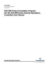
* The value entered in this eld must be calculated, multiply the specic gravity of the odorant to
be injected (typical values range between 0.5 and 1.0) by the value found on the name plate of the
pneumatic panel titled: Specic Volume Injector N°1.
Forexample,withanodorantspecicgravityof0.6andthespecicvolumeofInjector1being0.0132lb/s,
the entered value would be:
0.6 * 0.0132 = 0.00792 (entered value)
THISSTATION HAS BEEN CONSTRUCTED BY:
QUESTOIMPIANTOE'STATO REALIZZATO DA:
TIPO
TYPE
N°FABBR.
SERIAL N°
:
:
psi
:
:
:
:
BOLOGNAITA LY
psi
:
1450
OMT TARTARINIS.r.l.Via Paolo Fabbri,1
40013 Castelmaggiore BOLOGNA -ITA LY
gal
lb/s
:DOSAODOR-D Rev.1
Maximum drive pressure
Maximum operating pressure
Odorant flow range
Control device volume
Specific volume injector N°1
Specific volume injector N°2
TA RTARINI
O.M.T.
gal/h
***
***
Figure 17. Dosaodor-D Name Plate

16
Type Dosaodor-D
• Entered Volume For Injector 2 (pounds/second):
Theparameterisusedexclusivelyfortwoinjectorscongurationoftheproduct.
It indicates the quantity of odorant the injector is able to supply in one second of opening. If the system
parameters have not been set then the value will be equal to -1.
The injection value is recalculated during system operation (by means of feedback data).
Whenaregularrellmodeiscomplete,thesystemisabletorecalculatethespecicvolumeforaninjector
based on the actual odorant used.
** The value entered in this eld must be calculated, multiply the specic gravity of the odorant to be
injected (typical values range between 0.5 and 1.0) by the value found on the name plate of the
pneumatic panel titled: Specic Volume Injector N°2.
Forexample,withanodorantspecicgravityof0.6andthespecicvolumeofInjector1being0.0132lb/s,
the entered value would be:
0.6 * 0.0132 = 0.00792 (entered value)
• Volume For Switching Injectors (pounds):
When the user selects Injector 1 only (or Injector 2 only), the system will continue to use the selected injector
only, as programmed. When the option for Injectors 1 and 2 has been selected, the system will switch
between the two, based on a given volume of odorant. That volume of odorant is entered by the user
as the “Volume for Switching Injectors”. Every injection will subtract from this value, regardless of the
mode. The current value of this parameter can be viewed by the user as “Odorant Volume Remaining Before
Injector Switch”. In order to avoid inaccurate calculations caused by switching injectors midway through a
cylinderofodorant,thisswitchisonlydoneattheendofallcycle.Duetothis,thevolumeremainingbefore
injectorswitchwillbecomeslightlynegative.Thisindicatesthattheinjectorswillswitchattheendofthenextll
cycle. So the actual volume for switching injectors will be somewhat greater than the amount the user entered.
Odorant Data Conguration
This section must be completed with data that is related to the odorant contained in the supply tank.
• Odorant Weight (pounds/gallon):
Enterthespecicweightofodorantinpounds/gallon.
• Rated Odorant Calibration Cylinder Capacity (gallons):
Enterthecapacityoftheodorantcalibrationcylinderinthiseld.
*** The value that must be entered in this eld is indicated on the plate located on the pneumatic
panel in the eld: “Control device volume”. The value -1 indicates that the parameter must be initialized.
• Supply Tank Capacity (gallons):
Enter the maximum capacity of odorant in the supply tank in gallons.
• Supply Tank Low Alarm (gallons):
The user sets the tank volume level at which the alarm will activate. If the supply tank level is coming in from
the analog input, this can happen whenever the analog input value is less than or equal to the low alarm level
set by the user. If the tank level is “User Entered”, in other words if the user enters an initial tank volume, the
onlytimethisischeckedisattheendofallcycle,asthisshouldbetheonlytimethevolumeofthesupply
tank has changes.
• Current Supply Tank Volume (gallons):
Thiseldindicatestheamountofodorantinthetank.
When the supply tank level input selection is set to “Analog Input”, then the Current Supply Tank Volume will
supplythevalueprovidedtothesystemusingtheuserdenedanaloginput.Nochangeswillbemadetothisvalue
by the software. When the same input selection is set to “User Entered”, the user must enter an approximate
volume of odorant currently in the tank in “Current Supply Tank Volume” eld. Volume in the amount of the
enteredratedodorantcalibrationcylindercapacitywillbesubtractedbythesoftwareattheendofeachll
cycle.Whenthetankisrelled,theusermustenteranewapproximationvolumeofodorantinthetank.

17
Type Dosaodor-D
Operating Data Conguration
This section contains operating process parameters.
• Manual Mode Gas Flow Rate (gallons):
InManualMode,thegasowvaluethatisconsideredbythesoftwareisprovidedbyastaticvalueenteredby
theuserinthiseld.
• Minimum Rate Mode Flow Rate (gallons):
The Minimum Rate Mode is similar to the Manual Mode. Its purpose is to provide the user with an additional
optionforusewhenselectingthemodeofoperationduringanalarm.Theuserwouldtypicallyenteraowrate
inthiseldforuseinminimumratethatismuchlessthantherateenteredforManualMode.
• Maximum Odorant Calibration Cylinder Fill Time (seconds):
TheusermustsetaMaximumOdorantCalibrationCylinderFillTimevalueinthiseld.Thismaybedened
during startup (see Type Dosaodor-D Odorant Injection System Controlled By Type ROC809 Remote Telemetry
UnitForNorthAmericaInstallation(D103102X012)).Iftheodorantcalibrationcylinderllingtimeexceeds
the value set by the user,theodorantcalibrationcylinderlltimealarmwillbeactivated.The only way for this
alarm to clear is for the user to initiate an alarm reset.
Output Data
Thesystemcanprovideoutputpulsesrepresentingodorantinjectedorgasowtointerfacewithexternaldevices.
Theamountofodorantorowthateachpulserepresentsisuserselectable.Apulsewilllastfor0.2seconds.
• Pulse Output For Flow Accum (1 PULSE=) (MCF):
ThiselddeterminesthenumberofMCFassignedtoeachpulseoftheoutputchannelthatisusedtotransmit
thegasowtoexternalsystems.PleaseseetheI/Olisttotracetheoutputchannel.
• Pulse Output For Odorant Used (1 PULSE=) (pounds):
Thiselddeterminesthenumberofpoundsassignedtoeachpulseoftheoutputchannelthatisusedto
transmit the quantity of injected odorant. Please see the I/O list to trace the output channel.
• Concentration Prev/hr Analog Full Scale (pounds/MMCF):
Thiseldindicatestheodorantconcentrationvaluethatisrepresentedbytheanalogoutput100%value,for
previous hour concentration. Please see the I/O list to trace the output channel.
• Concentration Today Analog Full Scale (pounds/MMCF):
Thiseldindicatestheodorantconcentrationvaluethatisrepresentedbytheanalogoutput100%value,for
today concentration. Please see the I/O list to trace the output channel.
I/O Cards
SelectjusttheI/Ooptionalcardsthatarepresentinyourconguration.Therequiredcardsmaynotbedeselected
anddisplayagraydescription.Dataeldsthatarerelatedtounselectedoptionalcardhaveagraybackgroundand
are not writable.
Location Information
Thissectionisdisplayedinthecurrentpagebutcannotbemodied.Pleaserefertothedescriptionofparameters
in the section “System Conguration” (see page 13).
Alarm Output Contact Selection
Select the alarms that will activate the alarm contact.
A digital output channel is available to transmit alarms to an external device, multiple alarms can be selected.
PleaseseetheI/Olisttoidentifytheoutputchannel.Byaggingtheoptionassignedtothealarms,whenthey
occur, the alarm output signal will be raised. Pressing the “Acknowledge Button” on an active alarm will clear the
alarm contact.

18
Type Dosaodor-D
Alarm Conguration
The conditions that may activate the alarm output are the following:
• Flow Computer:
Thisalarmissetwhenthediscreteinputassignedtotheowcomputeralarmisdeactivated(Status-Off).Itis
cleared when the discrete input is activated (Status - On).
Iftheinputforthisalarmconditionisnotutilizedthenthepointshouldbemanuallyconguredtoeliminate
erroneousowcomputeralarms.Thisisdonebydisablingtheappropriatediscreteinputandsettingthe
statustoON.SeeDiscreteInputcongurationscreenexample,Figure19.
• Injector 1 and Injector 2:
Therearetwospecicconditionsthattriggeraninjectoralarm.Whenoneoftheseconditionsoccurs,the
system cannot clear the alarm without user intervention. In order to do this, the issue causing the alarm must
be solved, and the user must push the “Alarm Reset Button”.
• Supply Tank Low:
The user sets the volume level at which the alarm will be triggered in “System Conguration”. If the supply
tank level is coming in from the analog input, this can occur whenever the analog input value is less than or
equal to the low alarm level set by the user. If the tank level is “User Entered”, in other words if the user enters
aninitialtankvolume,theonlytimethisischeckedisattheendofallcycle,asthisshouldbetheonlytime
the volume of the supply tank changes.
Figure 18. View of Alarm Conguration

19
Type Dosaodor-D
• High Flow:
Shouldthecurrentdailyowratebecomegreaterorequaltothe“UserEntered”valueforahighowrateatimer
willstartforauserspeciedamountoftime.Ifatanytimebeforethetimerexpiresthecurrentdailyowrateshould
dipbackbelowthevalueforahighowrate,thetimerwillbestopped,andnoalarmwillbetriggered.Ifthetimer
runstoexpiration,thenahighowratealarmisactivated.Thealarmandtimerareresetwhenthecurrentdaily
owrategoesbelowthehighowratealarmvalue.Inaddition,thisalarmisactivatedonlyinAutoMode.
Highowratelevelandtimedelayisenteredin“FlowRateAlarm”section.
• Low Flow:
Thelowowratealarmoperationissimilartothehighowratealarm.Ifthecurrentdailyowratedropsbelow
the“UserEntered”lowowratealarmvalue,thenatimerstarts.Ifatanytimethecurrentdailyowratereturns
to an acceptable value, the alarm and timer are reset. This alarm is activated only in Auto Mode.
Lowowratelevelandtimedelayisenteredin“FlowRateAlarm”section.
• Odorant Calibration Cylinder Fill Time:
Theusersetsamaximumlltimevaluefortheodorantcalibrationcylinder.Whenallcyclebegins,atimer
isstarted.Shouldthetimerreachthemaximumlltimeenteredbytheuser,thelltimealarmfortheodorant
calibration cylinder will be activated. The alarm and timer can only be cleared by the user pushing the alarm
reset button.
Themaximumodorantcalibrationcylinderlltimeinsecondsisenteredin“OdorantCalibrationCylinderFill
Alarm” section.
Flow Rate Alarm
• High Flow Rate Alarm (gallons):
Thiselddeterminesthemaximumgasowratewhichcausesthesystemtogointoalarmmode.The
momentthemaximumowthresholdisexceeded,theactivationofthealarmwillhaveatimedelayequalto
thetimespeciedintheHIGH FLOW ALARM DELAYeld.Thealarmwillnotbeactivatediftheowvalue
returns to below the indicated threshold before the time delay has elapsed.
• Low Flow Rate Alarm (gallons):
Thiselddeterminestheminimumgasunderowwhichcausesthesystemtogointoalarmmode.The
momenttheminimumowthresholdisexceeded,theactivationofthealarmwillhaveatimedelayequal
tothetimespeciedintheLOW FLOW ALARM DELAYeld.Thealarmwillnotbeactivatediftheowvalue
returns to above the indicated threshold before the time delay has elapsed.
Figure 19. View of Discrete Input Conguration

20
Type Dosaodor-D
• High Flow Alarm Delay:
Thiselddeterminesthetimethatwillelapsebetweenthepassingofthemaximumowthresholdandthe
alarmactivation.Iftheowreturnstoanacceptablevaluewithintheconsideredtime,thealarmwillnotbe
activated and the relative timer will be reset.
Thethresholdispassedwhenowvaluesarehigherthanthoseofthespeciedthreshold.
• Low Flow Alarm Delay:
Thiselddeterminesthetimethatwillelapsebetweenthepassingoftheminimumowthresholdandthe
alarmactivation.Iftheowreturnstoanacceptablevaluewithintheconsideredtime,thealarmwillnotbe
activated and the relative timer will be reset.
Thethresholdispassedwhenowvaluesarelowerthanthoseofthespeciedthreshold.
Odorant Calibration Cylinder Fill Alarm
Maximum Odorant Calibration Cylinder Fill Time in Seconds.
Please refer to the “System Conguration” section for a description of this parameter (see page 13).
Flow Computer Alarm
Mode During Flow Computer Alarm.
Inthissectiontheusermaychoosethesystemoperationmodewhichtakesplacewhentheowcomputeralarm
is activated. The available operation modes are: Disable, manual, or minimum rate.
Low Flow Alarm
Mode During Low Flow Alarm.
Inthissectiontheusermaychoosethesystemoperationmodewhichtakesplacewhenthelowowcondition
alarm is activated. The operation modes available are: Disable, manual, minimum rate, or current mode (the
current operation mode is unchanged).
High Flow Alarm
Mode During High Flow Alarm.
Inthissectiontheusermaychoosethesystemoperationmodewhichtakesplacewhenthehighowalarm
condition alarm is activated.
The operation modes available are: Disable, manual, minimum rate, or current mode (the current operation mode
is unchanged).
Alarm Restart Options
Mode After The Alarm Clears.
Thissectiondenesthechosenbehaviorforthesystemwhenthealarmsarecleared.Theoptionsare:
• Remainincurrentmode.
• Returntopreviousoperationmodethatwasusedbeforethealarmevent.
For the alarm to clear, the event that caused the alarm must be solved.
The system can go back to the previous mode automatically if the alarm clears. For example, if the Flow Computer
Input caused an alarm and later cleared. If the restart option was set to return to previous mode, the program would
return to the previous mode when the alarm clears. In this example the alarm would clear automatically.
Injector Warnings
Theinjectorvariationwarningtakesplaceifthecurrentcalculatedinjectorspecicvolumehasvariedfromthe
lastvalueorfromtheenteredvaluebyanamountthatexceedsthewarninglimits.Theinjectorspecicvolume
isrecalculatedaftereveryrellcycleoftheodorantcalibrationcylindertoupdatetheprocessparametersandthe
process model.
/