Page is loading ...

Flow Computer Division
Form Number A6175
Part Number D301217X012
March 2006
ROC827 Remote Operations Controller
Instruction Manual

Issued Mar-06 ii
Revision Tracking Sheet
March 2006
This manual may be revised periodically to incorporate new or updated information. The
revision date of each page appears at the bottom of the page opposite the page number. A change
in revision date to any page also changes the date of the manual that appears on the front cover.
Listed below is the revision date of each page (if applicable):
Page Revision
Initial issue Mar-06
ROCLINK is a trademark of one of the Emerson Process Management companies. The Emerson logo is a trademark
and service mark of Emerson Electric Co. All other marks are the property of their respective owners.
© Fisher Controls International, LLC. 2006. All rights reserved. Printed in the U.S.A.
www.EmersonProcess.com/flow
While this information is presented in good faith and believed to be accurate, Fisher Controls does not guarantee
satisfactory results from reliance upon such information. Nothing contained herein is to be construed as a warranty
or guarantee, express or implied, regarding the performance, merchantability, fitness or any other matter with respect
to the products, nor as a recommendation to use any product or process in conflict with any patent. Fisher Controls
reserves the right, without notice, to alter or improve the designs or specifications of the products described herein.

Issued Mar-06 iii
Contents
Chapter 1 – General Information 1-1
1.1 Scope of Manual...............................................................................................................1-1
1.2 Hardware..........................................................................................................................1-2
1.2.1 Central Processor Unit (CPU)............................................................................1-5
1.2.2 Processor and Memory......................................................................................1-6
1.2.3 Real-Time Clock (RTC)......................................................................................1-6
1.2.4 Diagnostic Monitoring.........................................................................................1-7
1.2.5 Options...............................................................................................................1-7
1.3 FCC Information...............................................................................................................1-8
1.4 Firmware...........................................................................................................................1-8
1.4.1 Historical Database and Event & Alarm Log....................................................1-11
1.4.2 Meter Runs and Stations..................................................................................1-12
1.4.3 Flow Calculations.............................................................................................1-12
1.4.4 Automatic Self Tests ........................................................................................1-13
1.4.5 Low Power Modes............................................................................................1-13
1.4.6 Proportional, Integral, and Derivative (PID) .....................................................1-14
1.4.7 Function Sequence Table (FST)......................................................................1-14
1.5 ROCLINK 800 Configuration Software...........................................................................1-15
1.6 DS800 Development Suite Software..............................................................................1-16
1.7 Expanded Backplane......................................................................................................1-17
1.8 Related Specification Sheets..........................................................................................1-18
Chapter 2 – Installation and Use 2-1
2.1 Installation Requirements.................................................................................................2-1
2.1.1 Environmental Requirements.............................................................................2-2
2.1.2 Site Requirements..............................................................................................2-2
2.1.3 Compliance with Hazardous Area Standards ....................................................2-3
2.1.4 Power Installation Requirements .......................................................................2-4
2.1.5 Grounding Installation Requirements.................................................................2-4
2.1.6 I/O Wiring Requirements....................................................................................2-5
2.2 Required Tools .................................................................................................................2-5
2.3 Housing.............................................................................................................................2-5
2.3.1 Removing and Replacing End Caps ..................................................................2-6
2.3.2 Removing and Installing Wire Channel Covers..................................................2-6
2.3.3 Removing and Installing Module Covers............................................................2-7
2.4 Mounting the ROC827 on a DIN Rail...............................................................................2-7
2.4.1 Installing the DIN Rail.........................................................................................2-9
2.4.2 Securing the ROC827 on the DIN Rail...............................................................2-9
2.4.3 Removing the ROC827 from the DIN Rail .......................................................2-10
2.5 ROC800-Series Expanded Backplane (EXP) ................................................................2-10
2.5.1 Attaching an Expandable Backplane ...............................................................2-11
2.5.2 Removing an Expandable Backplane..............................................................2-12
2.6 Central Processor Unit (CPU) ........................................................................................2-13
2.6.1 Removing the CPU Module..............................................................................2-16
2.6.2 Installing the CPU Module................................................................................2-16
2.7 License Keys ..................................................................................................................2-17
2.7.1 Installing a License Key....................................................................................2-18
2.7.2 Removing a License Key..................................................................................2-19

Issued Mar-06 iv
2.8
Startup and Operation....................................................................................................2-19
2.8.1 Startup..............................................................................................................2-20
2.8.2 Operation..........................................................................................................2-20
Chapter 3 – Power Connections 3-1
3.1 Power Input Module Descriptions.....................................................................................3-1
3.1.1 12-Volt DC Power Input Module (PM-12)...........................................................3-1
3.1.2 24-Volt DC Power Input Module (PM-24)...........................................................3-3
3.1.3 Auxiliary Output (AUX+ and AUX–)....................................................................3-4
3.1.4 Switched Auxiliary Output (AUXSW+ and AUXSW–)........................................3-6
3.2 Determining Power Consumption.....................................................................................3-7
3.2.1 Tuning the Configuration..................................................................................3-11
3.3 Removing a Power Input Module ...................................................................................3-20
3.4 Installing a Power Input Module.....................................................................................3-21
3.5 Connecting the ROC827 to Wiring.................................................................................3-21
3.5.1 Wiring the DC Power Input Module..................................................................3-22
3.5.2 Wiring the External Batteries............................................................................3-23
3.5.3 Replacing the Internal Battery..........................................................................3-25
3.6 Related Specification Sheets..........................................................................................3-26
Chapter 4 – Input/Output Modules 4-1
4.1 I/O Module Overview........................................................................................................4-1
4.2 Installation.........................................................................................................................4-3
4.2.1 Installing an I/O Module......................................................................................4-4
4.2.2 Removing an I/O Module....................................................................................4-5
4.2.3 Wiring I/O Modules.............................................................................................4-6
4.3 Analog Input Modules.......................................................................................................4-6
4.4 Analog Output Modules....................................................................................................4-8
4.5 Discrete Input Modules.....................................................................................................4-9
4.6 Discrete Output Modules................................................................................................4-10
4.7 Discrete Output Relay Modules......................................................................................4-11
4.8 Pulse Input Modules.......................................................................................................4-12
4.9 RTD Input Modules.........................................................................................................4-14
4.9.1 Connecting the RTD Wiring..............................................................................4-15
4.10 J and K Type Thermocouple Input Modules..................................................................4-16
4.11 Related Specification Sheets.........................................................................................4-21
Chapter 5 – Communications 5-1
5.1 Communications Ports and Modules Overview...............................................................5-1
5.2 Installing Communication Modules..................................................................................5-3
5.3 Removing a Communications Module.............................................................................5-4
5.4 Wiring Communications Modules....................................................................................5-5
5.5 Local Operator Interface (LOI).........................................................................................5-5
5.5.1 Using the LOI .....................................................................................................5-7
5.6 Ethernet Communications................................................................................................5-7
5.7 EIA-232 (RS-232) Serial Communications......................................................................5-9
5.8 EIA-422/485 (RS-422/485) Serial Communications Module.........................................5-10
5.8.1 EIA-422/485 (RS-422/485) Jumpers & Termination Resistors........................5-11

Issued Mar-06 v
5.9
Dial-up Modem Communications Module......................................................................5-12
5.10 Multi-Variable Sensor (MVS) Interface Modules............................................................5-14
5.11 HART Interface Module .................................................................................................5-16
5.12 Related Specification Sheets.........................................................................................5-20
Chapter 6 – Troubleshooting 6-1
6.1 Guidelines.........................................................................................................................6-1
6.2 Checklists .........................................................................................................................6-2
6.2.1 Serial Communications ......................................................................................6-2
6.2.2 I/O Point..............................................................................................................6-2
6.2.3 Software .............................................................................................................6-3
6.2.4 Powering Up.......................................................................................................6-3
6.2.5 MVS Module.......................................................................................................6-3
6.3 Procedures .......................................................................................................................6-4
6.3.1 Preserving Configuration and Log Data.............................................................6-4
6.3.2 Restarting the ROC827......................................................................................6-4
6.3.3 Troubleshooting Analog Input Modules..............................................................6-5
6.3.4 Troubleshooting Analog Output Modules...........................................................6-7
6.3.5 Troubleshooting Discrete Input Modules............................................................6-7
6.3.6 Troubleshooting Discrete Output Modules.........................................................6-8
6.3.7 Troubleshooting Discrete Output Relay Modules...............................................6-8
6.3.8 Troubleshooting Pulse Input Modules................................................................6-8
6.3.9 Troubleshooting RTD Input Modules .................................................................6-9
6.3.10 Troubleshooting J and K Type Thermocouple Input Modules .........................6-10
Chapter 7 – Calibration 7-1
7.1 Calibration.........................................................................................................................7-1
7.2 Preparing for Calibration...................................................................................................7-1
Appendix A – Glossary A-1
Index I-1

Issued Mar-06 vi

ROC827 Instruction Manual
Issued Mar-06 General Information 1-1
Chapter 1 – General Information
This manual focuses on the hardware aspects of the ROC827 Remote
Operations Controller (the “ROC827”) and the ROC800-Series expanded
backplanes (“EXPs”). For information about the software, refer to the
ROCLINK™ 800 Configuration Software User Manual (Form A6121).
This chapter details the structure of this manual and provides an overview
of the ROC827 and its components.
In This Chapter
1.1 Scope of Manual......................................................................................1-1
1.2 Hardware .................................................................................................1-2
1.2.1 Central Processor Unit (CPU)........................................................1-5
1.2.2 Processor and Memory..................................................................1-6
1.2.3 Real-Time Clock (RTC)..................................................................1-6
1.2.4 Diagnostic Monitoring ....................................................................1-7
1.2.5 Options...........................................................................................1-7
1.3 FCC Information ......................................................................................1-8
1.4 Firmware..................................................................................................1-8
1.4.1 Historical Database and Event & Alarm Log................................1-12
1.4.2 Meter Runs and Stations .............................................................1-12
1.4.3 Flow Calculations.........................................................................1-12
1.4.4 Automatic Self Tests....................................................................1-13
1.4.5 Low Power Modes .......................................................................1-14
1.4.6 Proportional, Integral, and Derivative (PID).................................1-14
1.4.7 Function Sequence Table (FST)..................................................1-15
1.5 ROCLINK 800 Configuration Software..................................................1-15
1.6 DS800 Development Suite Software.....................................................1-17
1.7 Expanded Backplane.............................................................................1-18
1.8 Related Specification Sheets.................................................................1-19
The ROC827 Remote Operations Controller is a microprocessor-based
controller that provides the functions required for a variety of field
automation applications. The ROC827 is ideal for applications requiring
general logic and sequencing control; historical data archiving; multiple
communication ports; Proportional, Integral, and Derivative (PID) control;
and flow measurement on up to twelve meter runs. When attached to the
ROC827, the ROC800-Series expanded backplanes provide the ROC827
with increased I/O capabilities.
1.1 Scope of Manual
This manual contains the following chapters:
Chapter 1
General Information
Provides an overview of the hardware and
specifications for the ROC827 and the ROC800-Series
expanded backplane.

ROC827 Instruction Manual
Issued Mar-06 General Information 1-2
Chapter 2
Installation and Use
Provides information on installation, tools, wiring,
mounting the ROC827, and other essential elements of
the ROC827 and EXPs.
Chapter 3
Power Connections
Provides information on the Power Input modules
available for the ROC827 and EXPs and provides
worksheets to help determine power requirements for
the ROC827 configurations.
Chapter 4
Input/Output (I/O)
Modules
Provides information for the Input/Output (I/O) modules
available for the ROC827 and EXPs.
Chapter 5
Communications
Provides information for the built-in communications
and the optional communication modules available for
the ROC827.
Chapter 6
Troubleshooting
Provides information on diagnosing and correcting
problems for the ROC827.
Chapter 7
Calibration
Provides information for calibrating Analog Inputs,
HART Inputs, RTD Inputs, and MVS Inputs for the
ROC827.
Glossary Provides definitions of acronyms and terms.
Index
Provides an alphabetic listing of items and topics
contained in this manual.
1.2 Hardware
The ROC827 is highly innovative and versatile with an integrated
backplane to which the central processor unit (CPU), Power Input module,
communication modules, and I/O modules connect. The ROC827 has
three I/O module slots.
The ROC800-Series expanded backplane (EXP) attaches to the ROC827.
Each EXP provides six additional I/O module slots. The ROC827 can
support up to four EXPs, for a total of 27 I/O module slots in a fully
configured ROC827 (six slots per EXP plus the three I/O slots on the
ROC827 itself).
The ROC827 uses a Power Input module to convert external input power
to the voltage levels required by the ROC827’s electronics and to monitor
voltage levels to ensure proper operation. Two Power Input modules—12
Volts dc (PM-12) and 24 Volts dc (PM-24)—are available for the
ROC827. For more information on the Power Input modules, refer to
Chapter 3, Power Connections.
The ROC827 supports a variety of communication protocols: ROC Plus,
Modbus, Modbus TCP/IP, Modbus encapsulated in TCP/IP, and Modbus
with Electronic Flow Measurement (EFM) extensions.
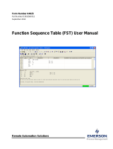
Figure 1-1 shows the housing, typical I/O modules, and communication
modules installed in a ROC827. The patented ABS (Acrylonitrile
Butadiene Styrene) plastic housing has wire covers to protect the wiring
terminals. The housing includes DIN rail mounts for mounting the
ROC827 on a panel or in a user-supplied enclosure.

ROC827 Instruction Manual
Issued Mar-06 General Information 1-3
Figure 1-1. ROC827 Base Unit (without Expanded Backplane)
The ROC827’s CPU contains the microprocessor, the firmware, a
connector to the backplane, three built-in communication ports, a Light-
Emitting Diode (LED) low power wakeup button, a RESET button, the
application license key connectors, a STATUS LED indicating system
integrity, diagnostic LEDs for two of the communications ports, and the
main processor.
CPU
LOI (Local Port)
EIA-232 (RS-232D)
Wire Channel Cover
Right End Cap
Power Supply Module
Built-in Ethernet (Comm1)
Built-in EIA-232 (RS-232C)
(Comm2)
I/O Module (1 of 3)

ROC827 Instruction Manual
Issued Mar-06 General Information 1-4
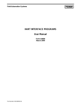
Figure 1-2 shows a typical expanded backplane (EXP) populated with a
full complement of six I/O modules. Each EXP is composed of the same
plastic housing as the ROC827, contains six I/O slots, and has a powered
backplane that easily attaches to the ROC827 and other EXPs.
Figure 1-2. ROC827 with One Expanded Backplane
The ROC827 and EXPs support nine types of Input/Output (I/O) modules,
which can satisfy a wide variety of field I/O requirements (refer to Chapter
4, Input/Output Modules). I/O modules include:
Analog Inputs (AI).
Analog Outputs (AO).
Discrete Inputs (DI).
Discrete Outputs (DO).
Digital Relay Outputs (DOR).
HART Inputs/Outputs.
Pulse Inputs (PI) – High/Low Speed.
Resistance Temperature Detector Inputs (RTD).
J and K Type Thermocouple (T/C) Inputs.

ROC827 Instruction Manual
Issued Mar-06 General Information 1-5
The ROC827 holds up to six communication ports (refer to Chapter 5,
Communications). Three communication ports are built-in:
Local Operator Interface (LOI) – Local Port EIA-232 (RS-232D).
Ethernet – Comm1 Port for use with the DS800 Development Suite
Software.
EIA-232 (RS-232C) – Comm2 Port for point-to-point asynchronous
serial communications.
Communication modules (which install in the ROC827’s Comm3,
Comm4, and Comm5 slots) provide additional ports for communicating
with a host computer or other devices. Modules include:
EIA-232 (RS-232C) – Point-to-point asynchronous serial
communications include Data Terminal Ready (DTR) support, Ready
To Send (RTS) support, and radio power control.
EIA-422/EIA-485 (RS-422/RS-485) – Point-to-point (EIA-422) or
multiple-point (EIA-485) asynchronous serial communications.
Multi-Variable Sensor (MVS) – Interfaces with MVS Sensors (up to
two modules per ROC827).
Dial-up modem – Communications over a telephone network (14.4K
V.42 bis with throughput up to 57.6K bps).
Hot-Swappable &
Hot-Pluggable
Modules—whether I/O or communication—easily install in the
module slots. Modules are both “hot-swappable” (they can be
removed and another module of the same kind installed while the
ROC827 is powered) and “hot-pluggable” (they can be installed
directly into unused module slots with the ROC827 is powered).
Modules are also self-identifying, which means that the ROCLINK
800 Configuration software recognizes the module (although you may
need to configure the module using the software). The modules have
extensive short circuit, overvoltage protection, and are self-resetting
after a fault clears.
1.2.1 Central Processor Unit (CPU)
The CPU contains the microprocessor, the firmware, connectors to the
backplane, the three built-in communication ports (two with LEDs), a
LED low power wakeup button, a RESET button, the application license
key connectors, a STATUS LED indicating system integrity, and the main
processor.
CPU components include:
32-bit microprocessor based on Motorola
MPC862 Quad Integrated
Communications Controller (PowerQUICC
™
) PowerPC
processor.
SRAM (Static Random Access Memory) with battery backup.
Flash ROM (Read-Only Memory).
SDRAM (Synchronous Dynamic Random Access Memory).

ROC827 Instruction Manual
Issued Mar-06 General Information 1-6
Diagnostic monitoring.
Real-Time Clock.
Automatic self-tests.
Power saving modes.
Local Operator Interface (LOI) EIA-232 (RS-232D) Local Port.
EIA-232 (RS-232C) serial Comm2 port.
Ethernet Comm1 port.
1.2.2 Processor and Memory
The ROC827 uses a 32-bit microprocessor with processor bus clock
frequency at 50 MHz with a watchdog timer. The Motorola MPC862
Quad Integrated Communications Controller (PowerQUICC) PowerPC
processor and the Real-Time Operating System (RTOS) provide both
hardware and software memory protection.
1.2.3 Real-Time Clock (RTC)
You can set the ROC827’s Real-Time Clock (RTC) for year, month, day,
hour, minute, and second. The clock provides time stamping of the
database values. The battery-backed clock firmware tracks the day of the
week, corrects for leap year, and adjusts for daylight savings time (user-
selectable). The time chip automatically switches to backup power when
the ROC827 loses primary input power.
The internal Sanyo 3-volt CR2430 lithium battery provides backup for the
data and the Real-Time Clock when the main power is not connected. The
battery has a one-year minimum backup life with the battery is installed,
the jumper disengaged, and no power applied to the ROC827. The battery
has a ten-year backup life with the backup battery installed and power
applied to the ROC827 or when the battery is removed from the ROC827.
Note: If the Real-Time Clock does not keep the current time when you
remove power, replace the lithium battery.

ROC827 Instruction Manual
Issued Mar-06 General Information 1-7
1.2.4 Diagnostic Monitoring
The ROC827 has diagnostic inputs incorporated into the circuitry for
monitoring system integrity. Use ROCLINK 800 software to access the
System Analog Inputs. Refer to Table 1-1.
Table 1-1. System Analog Inputs
System AI
Point Number
Function Normal Range
1 Battery Input Voltage 11.25 to 16 Volts dc
2 Charge in Voltage 0 to 18 Volts dc
3 Module Voltage 11.00 to 14.50 Volts dc
4 Not Used Not Used
5 On Board Temperature
–40 to 85C (–40 to
185F)
1.2.5 Options
The ROC827 allows you to choose from a wide variety of options to suit
many applications.
Optional communication modules include EIA-232 (RS-232) serial
communications, EIA-422/485 (RS-422/485) serial communications,
Multi-Variable Sensor (MVS), and dial-up modem communications (refer
to Chapter 5, Communications).
The ROC827 can handle up to two MVS interface modules. Each module
can provide power and communications for up to six MVS sensors, for a
total of up to 12 MVS sensors per ROC827 (refer to Chapter 5,
Communications).
Optional I/O modules include Analog Inputs (AI), Analog Outputs (AO),
Discrete Inputs (DI), Discrete Outputs (DO), Discrete Output Relays
(DOR), Pulse Inputs (PI), Resistance Temperature Detector (RTD) Inputs,
Thermocouple (T/C) Inputs, and Highway Addressable Remote
Transducers (HART) (refer to Chapter 4, Input/Output Modules).
The optional application license keys provide extended functionality, such
as the use of the DS800 Development Suite Software (the IEC 61131-3
compliant programming environment) and various user programs, and
enables embedded meter runs. For example, you need to install a license
key with the proper license in the ROC827 to perform AGA calculations.
Refer to Section 1.6, “DS800 Development Suite Software.”
The Local Operator Interface (LOI local port) communications terminal
requires the installation of an LOI cable between the ROC827 and your
PC. The LOI port uses an RJ-45 connector with a standard EIA-232
(RS-232D) pin out.

ROC827 Instruction Manual
Issued Mar-06 General Information 1-8
1.3 FCC Information
This equipment complies with Part 68 of the FCC rules. Etched on the
modem assembly is, among other information, the FCC certification
number and Ringer Equivalence Number (REN) for this equipment. If
requested, this information must be provided to the telephone company.
This module has an FCC-compliant telephone modular plug. The module
is designed to be connected to the telephone network or premises’ wiring
using a compatible modular jack that is Part 68-compliant.
The REN is used to determine the quantity of devices that may be
connected to the telephone line. Excessive RENs on the telephone line
may result in the devices not ringing in response to an incoming call.
Typically, the sum of the RENs should not exceed five (5.0). Contact the
local telephone company to determine the total number of devices that
may be connected to a line (as determined by the total RENs).
If this equipment and its dial-up modem causes harm to the telephone
network, the telephone company will notify you in advance that temporary
discontinuance of service may be required. However, if advance notice is
not practical, the telephone company will notify the customer as soon as
possible. In addition, you will be advised of your right to file a complaint
with the FCC if you believe it necessary.
The telephone company may make changes to its facilities, equipment,
operations, or procedures that could affect the operation of the equipment.
If this happens, the telephone company will provide advance notice so you
can make the necessary modifications to maintain uninterrupted service.
If you experience trouble with this equipment or the dial-up modem,
contact Emerson Process Management’s Flow Computer Division (at 641-
754-3923) for repair or warranty information. If the equipment harms the
telephone network, the telephone company may request that you
disconnect the equipment until the problem is resolved.
1.4 Firmware
The firmware that resides in Flash Read-Only Memory (ROM) contains
the operating system, ROC Plus communications protocol, and application
software. The CPU module provides battery-backed Static Random
Access Memory (SRAM) for saving configurations, storing events,
alarms, and the historical logs.
The ROC800-Series Operating System firmware provides a complete
operating system for the ROC827. The firmware in the ROC827 is field-
upgradeable using a serial connection or the Local Operator Interface
(LOI) local port. For more information, refer to the ROCLINK 800
Configuration Software User Manual (Form A6121).
The firmware supports:
Input/Output Database.

ROC827 Instruction Manual
Issued Mar-06 General Information 1-9
Historical Database.
Event and Alarm Log Databases.
Applications (PID, AGA, FST, and such).
Measurement Station Support.
Determining Task Execution.
Real-Time Clock.
Establishing and Managing Communications.
Self-Test Capability.
The firmware makes extensive use of configuration parameters, which you
configure using ROCLINK 800 software.
RTOS
The ROC800-Series firmware uses a pre-emptive, multi-tasking,
message-based Real-Time Operating System (RTOS) with hardware-
supported memory protection. Tasks are assigned priorities and, at any
given time, the operating system determines which task will run. For
instance, if a lower priority task is executing and a higher priority task
needs to run, the operating system suspends the lower priority task,
allows the higher priority task to run to completion, then resumes the
lower priority task’s execution. This is more efficient than a “time
sliced” architecture type.
TLP
The ROC827 reads data from and writes data to data structures called
“points.” A “point” is a ROC Plus Protocol term for a grouping of
individual parameters (such as information about an I/O channel) or
some other function (such as a flow calculation). Points are defined by
a collection of parameters and have a numerical designation that
defines the type of point (for example, point type 101 refers to a
Discrete Input and point type 103 refers to an Analog Input).
The logical number indicates the physical location for the I/O or the
logical instance for non-I/O points within the ROC827. Parameters are
individual pieces of data that relate to the point type. For instance, the raw
A/D value and the low scaling value are parameters associated with the
Analog Input point type, 103. The point type attributes define the database
point to be one of the possible types of points available to the system.
Together, these three components—the type (T), the logical (L), and the
parameters (P)—can be used to identify specific pieces of data that reside
in a ROC827’s data base. Collectively, this three-component address is
often called a “TLP.”
I/O Database
The Input/Output database contains the input and output points the
operating system firmware supports, including the System Analog
Inputs, Multi-Variable Sensor (MVS) inputs, and Input/Output (I/O)
modules. The firmware automatically determines the point type and
point number location of each installed I/O module. It then assigns
each input and output to a point in the database and includes user-
defined configuration parameters for assigning values, statuses, or
identifiers. The firmware scans each input, placing the values into the

ROC827 Instruction Manual
Issued Mar-06 General Information 1-10
respective database point. These values are available for display and
historical archiving.
SRBX
Spontaneous-Report-by-Exception (SRBX or RBX) communication
allows the ROC827 to monitor for alarm conditions and, upon
detecting an alarm, automatically reports the alarm to a host computer.
Any kind of communications link—dial-up modem or serial line—can
perform SRBX as long as the host is set up to receive field-initiated
calls.
Protocols
The firmware supports both the ROC Plus protocol and the Modbus
master and slave protocol. ROC Plus protocol can support serial
communications and radio or telephone modem communications to
local or remote devices, such as a host computer. The firmware also
supports the ROC Plus protocol over TCP/IP on the Ethernet port. The
ROC Plus protocol is similar to the ROC 300/400/500 protocol, since
it used many of the same opcodes. For more information, contact your
local sales representative.
The ROC800-Series firmware also supports Modbus protocol as either
master or slave device using Remote Terminal Unit (RTU) or American
Standard Code for Information Interchange (ASCII) modes. This allows
you to easily integrate the ROC827 into other systems. Extensions to the
Modbus protocol allow the retrieval of history, event, and alarm data in
Electronic Flow Metering (EFM) Measurement applications.
Note: In Ethernet mode, the firmware support Modbus only in slave mode.
Security
The ROCLINK 800 software also secures access to the ROC827. You
can define and store a maximum of 16 case-sensitive user identifiers
(User IDs). In order for the ROC827 to communicate, a case sensitive
log-on ID supplied to the ROCLINK 800 software must match one of
the IDs stored in the ROC827.
The operating system firmware supports the application-specific firmware
supplied in the Flash ROM. The application firmware includes
Proportional, Integral, and Derivative (PID) Control; FSTs; Spontaneous-
Report-By-Exception (SRBX) Communications Enhancement; optional
American Gas Association (AGA) Flow calculations with station support;
and optional IEC 61131-3 language programs (using DS800 Development
Suite software). Applications reside, so you do not need to re-build and
download the firmware for changes in calculation method.
Input Module
Addressing
The ROC800-Series firmware, by default, supports 16 addressable
points per module slot. However, to accommodate all the ROC827’s
expanded input capabilities (up to 27 module slots), you must set the
firmware to support eight (8) addressable points per module slot.
(Accomplish this using ROCLINK 800 and selecting ROC >
Information. On the Device Information screen’s General tab, click
the 8-Points Per Module radio button in the Logical Compatibility
Mode frame.)

ROC827 Instruction Manual
Issued Mar-06 General Information 1-11
The difference between 16-point and 8-point addressing becomes critical
when you have a host device reading data from specific TLPs. For
example, under 16-point addressing, channel 2 for a DI module in slot 2 is
referenced by TLP 101,33,3. Under 8-point addressing, channel 2 for a DI
module in slot 2 is referenced by TLP 101,17,23. Table 1-2 illustrates the
difference between 8-point and 16-point addressing.
Table 1-2. 16-Point vs. 8-Point Addressing
Slot Number Logicals (16 pt) Logicals (8 pt)
0 0–15 0–7
1 16–31 8–15
2 32–47 16–23
3 48–63 24–31
4 64–79 32–39
5 80–95 40–47
6 96–111 48–55
7 112–127 56–63
8 128–143 64–71
9 144–159 72–79
10 N/A 80–87
11 N/A 88–95
12 N/A 96–103
13 N/A 104–111
14 N/A 112–119
15 N/A 120–127
16 N/A 128–135
17 N/A 136–143
18 N/A 144–151
19 N/A 152–159
20 N/A 160–167
21 N/A 168–175
22 N/A 176–183
23 N/A 184–191
24 N/A 192–199
25 N/A 200–207
26 N/A 208–215
27 N/A 216–223
Note: 16-point addressing is the default for the ROC800-Series firmware.
To maximize the expanded input capabilities of the ROC827, you must
use ROCKLINK 800 to modify the firmware addressing to use 8-points
per module.
1.4.1 Historical Database and Event & Alarm Log
The historical database provides archiving of measured and calculated
values for either on-demand viewing or saving to a file. It provides an
historical record in accordance with API Chapter 21.1. You can configure
each of up to 200 points in the historical database to archive values under
various schemes, such as averaging or accumulating, as appropriate for the
type of database point.

ROC827 Instruction Manual
Issued Mar-06 General Information 1-12
The historical database is maintained in 11 segments. You can configure
each segment in the database to archive selected points at specified time
intervals. The segments can continuously archive or can be turned on and
off.
You can distribute history points among history segments 1 through 10
and the general history segment. For each history segment, you can
configure the number of periodic history values archived, the frequency of
archiving periodic values, the number of daily values archived, and the
contract hour. The number of minute values is fixed at 60. The 200 points
provide a total of over 197,000 entries (equal to more than 35 days of 24-
hour data for 200 points).
The Event Log records the last 450 parameter changes, power on and off
cycles, calibration information, and other system events. The event is
recorded along with a date and time stamp. The Alarm Log records the last
450 configured occurrences of alarms (set and clear). You can view the
logs, save them to a disk file, or print them using ROCLINK 800 software.
1.4.2 Meter Runs and Stations
You can group similarly configured meter runs into stations, which
provide great benefits during configuration and reporting. You can also
configure each meter run, which eliminates redundant meter run data
within a station and enables faster data processing.
You can group meter runs among the maximum of twelve stations in any
combination. Meter runs belong in the same station when they have the
same gas composition data and calculation methods. Stations allow you to:
Set contract hours differently for each station.
Designate several individual meter runs as part of a station.
Configure one to twelve meter runs for each station.
1.4.3 Flow Calculations
Gas and liquid calculation methods include:
AGA and API Chapter 21 compliant for AGA linear and differential
meter types.
AGA 3 – Orifice Plates for gas.
AGA 7 – Turbine Meters (ISO 9951) for gas.
AGA 8 – Compressibility for Detailed (ISO 12213-2), Gross I (ISO
12213-3), and Gross II for gas.
ISO 5167 – Orifice Plates for liquid.
API 12 – Turbine Meters for liquid.
ROC827 firmware completes full calculations every second on all
configured runs (up to 12) for AGA 3, AGA 7, AGA 8, ISO 5167, and
ISO 9951.

ROC827 Instruction Manual
Issued Mar-06 General Information 1-13
AGA 3 calculations conform to the methods described in American Gas
Association Report No. 3, Orifice Metering of Natural Gas and Other
Related Hydrocarbon Fluids. Based on the second and third editions, the
calculation method is 1992 AGA 3.
The AGA 7 calculations conform to methods described in American Gas
Association Report No. 7, Measurement of Gas by Turbine Meters, and
use the AGA 8 method for determining the compressibility factor.
The AGA 8 method calculates the compressibility factor based on the
physical chemistry of the component gasses at specified temperatures and
pressures.
The firmware supports liquid calculation methods ISO 5167 and API 12.
Factors for API 12 correction must be supplied through a Function
Sequence Table (FST) or user program. For more information, refer either
to the Function Sequence Table (FST) User Manual (Form A4625) or the
ROCLINK 800 Configuration Software User Manual (Form A6121).
1.4.4 Automatic Self Tests
The operating system firmware supports diagnostic tests on the ROC827
hardware, such as RAM integrity, Real-Time Clock operation, input
power voltage, board temperature, and watchdog timer.
The ROC827 periodically performs the following self-tests:
Voltage tests (battery low and battery high) ensure the ROC827 has
enough power to run while not allowing the battery to be overcharged.
The ROC827 operates with 12 Volts dc (nominal) power. The LEDs
become active when input power with the proper polarity and startup
voltage (9.00 to 11.25 Volts dc) is applied to the BAT+ / BAT–
connectors. Refer to Table 1-1.
The CPU controls the software “watchdog.” This watchdog checks the
software for validity every 2.7 seconds. If necessary, the processor
automatically resets.
The ROC827 monitors Multi-Variable Sensor(s), if applicable, for
accurate and continuous operation.
A memory validity self-test is performed to ensure the integrity of
memory.
1.4.5 Low Power Modes
The ROC827 uses low power operation under predetermined conditions
and supports two low power modes, Standby and Sleep.
Standby
The ROC827 uses this mode during periods of inactivity. When the
operating system cannot find a task to run, the ROC827 enters Standby
mode. This mode keeps all peripherals running and is transparent to

ROC827 Instruction Manual
Issued Mar-06 General Information 1-14
the user. The ROC827 wakes from Standby mode when it needs to
perform a task.
Sleep
The ROC827 uses this mode if it detects a low battery voltage. The
System AI Battery Point Number 1 measures the battery voltage and
compares it to the LoLo Alarm limit associated with this point. (The
default value for the LoLo Alarm limit is 10.6 Volts dc.) When in
Sleep mode, AUX
sw
is turned off. For information on configuring
alarms and System AI points, refer to the ROCLINK 800
Configuration Software User Manual (Form A6121).
Note: Sleep mode applies only to ROC827s using the 12 V dc Power
Input module (PM-12).
1.4.6 Proportional, Integral, and Derivative (PID)
The PID Control applications firmware provides Proportional, Integral,
and Derivative (PID) gain control for the ROC827 and enables the stable
operation of 16 PID loops that employ a regulating device, such as a
control valve.
The firmware sets up an independent PID algorithm (loop) in the
ROC827. The PID loop has its own user-defined input, output, and
override capability.
The typical use for PID control is to maintain a Process Variable at a
setpoint. If you configure PID override control, the primary loop is
normally in control of the regulating device. When the change in output
for the primary loop becomes less or greater (user-definable) than the
change in output calculated for the secondary (override) loop, the override
loop takes control of the regulating device. When the switchover
conditions are no longer met, the primary loop regains control of the
device. Parameters are also available to force the PID into either loop or
force it to stay in one loop.
1.4.7 Function Sequence Table (FST)
The Function Sequence Table (FST) applications firmware gives analog
and discrete sequencing control capability to the ROC827. This
programmable control is implemented in an FST, which defines the
actions the ROC827 performs using a series of functions. To develop
FSTs, you use the FST Editor in the ROCLINK 800 Configuration
software.
The function is the basic building block of an FST. You organize
functions in a sequence of steps to form a control algorithm. Each function
step can consist of a label, a command, and associated arguments. Use
labels to identify functions and allow branching to specific steps within an
FST. You select commands from a library of mathematical, logical, and
other command options. Command names consist of up to three characters
/