Page is loading ...

LED.com
© 2023 Current Lighting Solutions, LLC. All rights reserved. Information and specifications subject to change
without notice. All values are design or typical values when measured under laboratory conditions.
Page 1 of 5
(Rev 05/18/23)
IND506-Lumination-LPS-Series-LED-120-277V-Installation-Guide_R01
Installation Guide
IND506 | A-1006754
Lumination® LED Luminaire
LPS Series
BEFORE YOU BEGIN
Read these instructions completely and carefully.
WARNING / AVERTISSEMENT
RISK OF ELECTRIC SHOCK
• Turn power o before inspection, installation or removal.
• Properly ground electrical enclosure.
RISK OF FIRE
• Follow all NEC and local codes.
• Use only UL approved wire for input/output connections.
Only use size 18 AWG.
Prepare Electrical Wiring
Electrical Requirements
The LED driver must be supplied with 120-277 VAC, 50/60
Hz and connected to an individual properly grounded
branch circuit, protected by a 15 or 20 ampere circuit
breaker. Use min. 75°C supply conductor.
Grounding Instructions
The grounding and bonding of the overall system shall be
done in accordance with National Electric Code (NEC)
Article 600 and local codes.
RISQUES DE DÉCHARGES ÉLECTRIQUES
• Coupez l’alimentation avant d’inspecter, installer ou déplacer le luminaire.
• Assurez-vous de correctement mettre à la terre le boîtier d’alimentation
électrique.
RISQUES D’INCENDIE
• Respectez tous les codes NEC et codes locaux.
• N’utilisez que des ls approuvés par UL pour les entrées/sorties de
connexion. Taille minimum 18AWG ou 14 AWG.
Save These Instructions
Use only in the manner intended by the manufacturer.
If you have any questions, contact the manufacturer.
1-888-694-3533 or lightingprodinfo@Currentlighting.
com

LED.com
© 2023 Current Lighting Solutions, LLC. All rights reserved. Information and specifications subject to change
without notice. All values are design or typical values when measured under laboratory conditions.
Page 2 of 5
(Rev 05/18/23)
IND506-Lumination-LPS-Series-LED-120-277V-Installation-Guide_R01
Lumination® - LPS Series Installation Guide
Carefully unpack the LPS xture and optional refractor. Properly inspect each unit for defects before installing.
Wear work gloves to prevent dirt and oil from being transferred to the luminarie.
1
Choose an appropriate mounting method for the luminaire. Follow all UL/cUL, NEC, and minimum load rating
guidelines when selecting and installing a chain or cable.
2
• M4 Phillips head screwdriver.
• M5 Hex Phillips head screwdriver.
• M5 hexagon socket wrench head screwdriver.
• UL/cUL Recognized wire connectors.
• Safety tether and tting hook.
Tools and Components Provided in the Package
• Luminaire with 10’ cord and hook
• Accessory Refractor - ordered separate
• Accessory Drop Lens and Clamp - ordered separate
• Accessory Male and Female Hook - ordered separate
• Accessory U-Bracket - ordered separate
• Accessory Safety Tether - ordered separate
Accessory List
Accessory Name Product Code Description
Refractor 93099795 16” High bay Moonglow™ refractor 80
Drop Lens and Clamp 93083042 16” Conical Drop Lens with Clamp
Pendant Male Hook 14686 Pendant Loop, 3/4” Male NPT
Pendant Female Hook 27414 Pendant Loop, 3/4” Female NPSC
U-Bracket 93099238 LPS U-bracket Wall Mount
Safety Tether 93099239 LPS Safety tether (0.71m/2.3ft)
Installation of Units
LPS Fixture Weight
Fixture 120-277V Version w/o accessory 120-277V Version w/ accessory
LPS0XXX 8.8lbs/4.0kg 12.1lbs/5.5kg
3 4
First, unfasten the M4 screw of luminaire and
carefully tighten hook on the luminaire by tool.
Fix anti-rotation M4 screw to secure the hook to
the xture.
Optional: To install safety tether, unfasten one
screw from driver enclosure and put the safety
tether on the bolt. Use screwdriver to secure
tether to the driver enclosure and heatsink.

LED.com
© 2023 Current Lighting Solutions, LLC. All rights reserved. Information and specifications subject to change
without notice. All values are design or typical values when measured under laboratory conditions.
Page 3 of 5
(Rev 05/18/23)
IND506-Lumination-LPS-Series-LED-120-277V-Installation-Guide_R01
Lumination® - LPS Series Installation Guide
Plastic nut (4 pcs.)
Refractor
Self-tapping screw (4 pcs.)
Bracket (4 pcs.)
Provided hardware
Arrange all four brackets around the lens frame.
5
Refractor Installation (optional)
If using a refractor, attach the refractor to the luminaire using the provided lock bolts and plastic nuts. All 4 bolts
must be used to secure the refractor to the refractor brackets.
Fasten with
self-tapping screw
Align hole in bracket
over screw in frame
Fasten each bracket to the lens frame with
self-tapping screw.
6
Align holes in refractor over the standos on
the brackets and t in place.
7
Secure refractor place using plastic nuts.
NOTE: Only tighten the plastic nuts by hand,
avoid the nuts unfastened from luminaire by
vibration.
8

LED.com
© 2023 Current Lighting Solutions, LLC. All rights reserved. Information and specifications subject to change
without notice. All values are design or typical values when measured under laboratory conditions.
Page 4 of 5
(Rev 05/18/23)
IND506-Lumination-LPS-Series-LED-120-277V-Installation-Guide_R01
Lumination® - LPS Series Installation Guide
Hanging Options
Cable or Chain
Carefully connect the hanging hook on the luminaire to the
selected mounting chain or cable.
NOTE: Must ensure the structure and the suspending cable /
chain are suitable for the weight of the xture.
NOTE: Ensure M4 screw on the hook is screwed into the
hook correctly.
Pendant (options 1)
If mounting to a pendant solution, attach an appropriate
mounting hook to the xture ring, ensuring set screws or
clips are securely in place. Attach the threaded hook end to
the pendant pipe and use appropriate J-Box cover.
BRAND HOOK THREAD
GE Pedant LOOPF 3/4” Female NPSC
GE Pedant LOOPM 3/4” Male NPT
Pendant (options 2)
If mounting to a pendant solution, attach an appropriate
mounting hook to the xture ring, ensuring set screws or
clips are securely in place. Attach the threaded hook end to
the pendant pipe and use appropriate J-Box cover.
U-Bracket
If installing U-bracket wall mounting the xture, x the
U-bracket with two bolts and washers on the side of driver
enclosure. Suggest using 3/8” (M10) screw and thickness
2.0mm min washer to x bracket on the wall.
NOTE: If changing the direction of xture is required,
loosen the M5 screws and tilt the luminaire to determined
direction. If determined, use hexagon socket wrench to x
the screw tightly.
M4 screw
U-Bracket

LED.com
© 2023 Current Lighting Solutions, LLC. All rights reserved. Information and specifications subject to change
without notice. All values are design or typical values when measured under laboratory conditions.
Page 5 of 5
(Rev 05/18/23)
IND506-Lumination-LPS-Series-LED-120-277V-Installation-Guide_R01
Lumination® - LPS Series Installation Guide
AC line
Connect the wires from the xture following all
NEC and local electrical codes.
NOTE: Prior to installation, disconnect all
incoming power to the xture.
NOTE: Must use UL and cUL listed canopy for
AC line connected to branch circuit, also must
seal the seam using silicone sealant between
canopy and junction box, when nish the wire
connection.
NOTE: Must use UL and cUL listed waterproof
strain relief bushing for cable of branch circuit
connection.
1
Cable clip
Dimming line
(violet & gray)
6V DC output
for sensor (black)
Remove cap
If dimming wire connection is required, pull out
the dimming wire from cable clip, and carefully
press back plastic cover on the heatsink.
NOTE: Must strip the cable jacket. Also need to
strip o 10mm from the violet and pink wires.
NOTE: Must use waterproof connector to
connect the dimming wire.
2
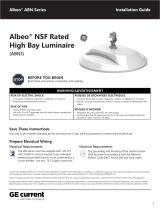
Electrical Connections
Line (Black)
Neutral (White)
Driver
LED
DC+
DC-
Dim+(Violet) Dim-(Gray)
LED
Ground (Green/Yellow)
Electrical Connections
Risk of Damage: Must use UL approved conduit ttings for all enclosure box connections to prevent wire cuts by sharp edges and
excessive strain on wiring.
This device complies with Part 15 of the FCC Rules. Operation is subject to the following two conditions: (1) This device may
not cause harmful interference, and (2) this device must accept any interference received, including interference that may cause
undesired operation. CAN ICES-005 (A) / NMB-005 (A)
Note: This equipment has been tested and found to comply with the limits for a Class A digital device, pursuant to part 15 of the
FCC Rules. These limits are designed to provide reasonable protection against harmful interference when the
equipment is operated in a commercial environment. This equipment generates, uses, and can radiate radio frequency
energy and, if not installed and used in accordance with the instruction manual, may cause harmful interference to radio
communications. Operation of this equipment in a residential area is likely to cause harmful interference in which case the user
will be required to correct the interference at his own expense.
(Pink)
pink)
/