Page is loading ...

LED.com
© 2023 Current Lighting Solutions, LLC. All rights reserved. Information and specifications subject to change
without notice. All values are design or typical values when measured under laboratory conditions.
Page 1 of 12
(Rev 05/30/23)
IND399-Lumination-LUR-Series-LED-Luminaire-Installation-Guide_R01
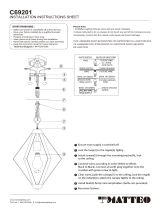
Installation Guide
IND399
Lumination® LED Luminaire
Suspended Linear Retrot Kit
(LUR Series)
BEFORE YOU BEGIN
Read these instructions completely and carefully.
WARNING/AVERTISSEMENT
RISK OF FIRE OR ELECTRIC SHOCK
• Turn power o before inspection, installation or removal.
• Properly ground electrical enclosure.
• Follow all NEC and local codes.
• Only those open holes indicated in the photographs and/or drawings may be made or altered as a result of kit installation. Do not
leave any other open holes in an enclosure of wiring or electrical components.
• LUR LED retrot kit installation requires knowledge of luminaires electrical systems. If not qualied, do not attempt installation.
Contact a qualied electrician.
• To prevent wiring damage or abrasion, do not expose wiring to edges of sheet metal or other sharp objects.
• Install this kit only in the luminaires that have the construction features and dimensions shown in the photographs and/or drawings
and where the input rating of the retrot kit does not exceed the input rating of the luminaire.
• Use only UL approved wire for input/output connections. Minimum size 18 AWG or 14 AWG for continuous runs.
• When using multi-branch wire circuits with a shared neutral, do not operate any circuit with the neutral open. Also ensure all
neutral connections are secure before energizing the circuit. An open neutral can cause an overvoltage condition at the luminaire
power supply.
This device complies with Part 15 of the FCC Rules. Operation is subject to the following two conditions: (1) This device may not cause harmful interference, and
(2) this device must accept any interference received, including interference that may cause undesired operation. CAN ICES-005 (A) / NMB-005 (A).
NOTE: This equipment has been tested and found to comply with the limits for a Class A digital device, pursuant to part 15 of the FCC Rules. These limits
are designed to provide reasonable protection against harmful interference when the equipment is operated in a commercial environment. This equipment
generates, uses, and can radiate radio frequency energy and, if not installed and used in accordance with the instruction manual, may cause harmful interference
to radio communications. Operation of this equipment in a residential area is likely to cause harmful interference in which case the user will be required to
correct the interference at his own expense.

LED.com
© 2023 Current Lighting Solutions, LLC. All rights reserved. Information and specifications subject to change
without notice. All values are design or typical values when measured under laboratory conditions.
Page 2 of 12
(Rev 05/30/23)
IND399-Lumination-LUR-Series-LED-Luminaire-Installation-Guide_R01
Lumination® (LUR - Series) Installation Guide
Save These Instructions
These instructions do not purport to cover all details or variations in components nor to provide for every possible contingency to be
met in connection with installation, operation or maintenance. Should further information be desired or should particular problem arise
which are not covered suciently for the purchaser’s purpose, the matter should be referred to General Electric Company. GE does not
claim liability for any installation not performed according to this guide or not by a qualied electrician.
Prepare Electrical Wiring
Electrical Requirements
The LED xture must be supplied with 120-277VAC, 50/60Hz
and protected by a max. 20A circuit breaker. Use min. 75°C
supply conductor.
Important Notes for Installation
IMPORTANT - Maximum Length of Electrical Run
Ensure that maximum safe working load of the xture’s suspension brackets is not exceeded after LUR retrot kit is added.
Required Tools
• Wire cutters/strippers
• Portable drill with 1/4” hex drive bit
• Punch tool 1/4”
• Screwdriver for ballast mounting screws
IMPORTANT - During Installation
1. When installing, use clean gloves in order to avoid fouling the reective surface.
2. To ensure a clean xture, install the xture with the plastic bag around the xture, and then remove plastic bag upon completion of
any and all construction related activity.
3. All provided screws must be screwed in and tightened to ensure that the retrot kit is safely attached to existing luminaire. Max
torque: 33 lbf-in.
4. Minimum distance from ceiling to luminaire: 3”.
5. Minimum distance between heat producing components: 3”.
6. Minimum size of enclosure: the existing luminaire being retrotted must have an electrical enclosure of 48” by 3” by 1.5” or greater.
7. It is recommended to use the optional tether kit (93064841) to ensure extra mechanical security on nal install.
8. Do not remove spacers on the brackets’ screws, as they are meant to stay on screws after installation.
9. Cap 0-10V dimming gray and purple wires (see Wiring Diagram) if not in use.
Grounding Instructions
The grounding and bonding of the overall system shall be
done in accordance with National Electric Code (NEC) Article
600 and local codes.
IMPORTANT - Maximum Length of Electrical Run
Lumen Code
Voltage [42] [84] [52] [A0] [62] [A2]
120V 232’ 176’ 160’
277V 536’ 412’ 369’

LED.com
© 2023 Current Lighting Solutions, LLC. All rights reserved. Information and specifications subject to change
without notice. All values are design or typical values when measured under laboratory conditions.
Page 3 of 12
(Rev 05/30/23)
IND399-Lumination-LUR-Series-LED-Luminaire-Installation-Guide_R01
Lumination® (LUR - Series) Installation Guide
Wire clip
GE LED driver
Grommets Bridge End caps
#8 hex head
drilling screws
DC connector
LED light engine
Brackets
Locking mechanism
and pins
Tethers (optional)
Components
NOTE: Appearance of components may vary slightly depending on xture being retrotted.
Tombstone
Grommets
LED light engine
Fixture
Belly pan and screws
#8 hexhead
Bracket and locking
mechanism(s)
drilling screw
End cap

LED.com
© 2023 Current Lighting Solutions, LLC. All rights reserved. Information and specifications subject to change
without notice. All values are design or typical values when measured under laboratory conditions.
Page 4 of 12
(Rev 05/30/23)
IND399-Lumination-LUR-Series-LED-Luminaire-Installation-Guide_R01
Lumination® (LUR - Series) Installation Guide
Important Notes When Handling
AK-LUR-A-T2-20-XXXX
Sensor holder with sensor will have Node Identication Label
for customer’s oor plan. Please do not throw away.
AK-LXX-A-LG-20-XXXX
Control module (PIHN-W005A) will have Node Identication
Label for customer’s oor plan. Please do not throw away
Installation of a Retrot Kit
NOTE: Fixture shown below is an example; please follow steps as needed according to the xture being retrotted.
1
2
Remove the uorescent tubes.
Open xture (remove belly pan) and remove the old
ballast.
Install LED driver using the ballast mounting screws and
connect it to existing power previously utilized by the
uorescent ballast.
NOTE: Connect 0-10V dimming wires (pink and purple)
to dimming controllers or sensors; if not in use, cap these
wires.
NOTE: For additional control options, refer to page 13.
3
Gray Purple
Red Blue
Black
White
GE LED Driver
Make two 1/4” holes in belly pan using a punch tool.
NOTE: Locate the hole(s) wherever possible (examples
shown) such that the belly pan does not deform and the
red/blue wires of the driver can reach through to the red/
black wires of the LED light engine.
NOTE: Add additional holes as needed for sensor
connection.
NOTE: It is recommended to place the hole(s) such
that each hole: is not visible below the xture, does not
require punching through multiple pieces of metal, and is a
maximum of 1.6” (as shown) from the tombstones.
4
New holes for
grommets
(1/4” diameter)
Existing holes
for screws
max. 1.6”
Tombstones
Insert grommets in belly pan.
5
Pass red and blue wires of the LED driver through the
grommets (one wire per grommet).
6
Red
Blue
Pink

LED.com
© 2023 Current Lighting Solutions, LLC. All rights reserved. Information and specifications subject to change
without notice. All values are design or typical values when measured under laboratory conditions.
Page 5 of 12
(Rev 05/30/23)
IND399-Lumination-LUR-Series-LED-Luminaire-Installation-Guide_R01
Lumination® (LUR - Series) Installation Guide
NOTE: The following brackets use a locking mechanism.
NOTE: All with tombstones come with one drilling screw. All brackets without tombstones come with two drilling screws.
Stationary
tombstone Adjustable
tombstone
7A 7B
7C
7
BRACKETS (A) OR (B) OR (C): Rotate the locking mechanism(s) on each bracket to the unlocked position as shown.
Good
Alignment
Bad
Alignment
Press down on both
tabs at the same time
8
BRACKET (A): In the unlocked position, check if the pins from both locking mechanisms can slide into the slots in the xture’s
tombstones at the same time (left). If they are not aligned, press down on the tabs and slide the mechanism left or right to match the
distance between the tombstones (left). Check alignment and repeat until correct alignment found. Move locking mechanisms on all
brackets to the same position before proceeding to next step.
NOTE: The locking mechanism must be aligned on the bracket as shown (right).

LED.com
© 2023 Current Lighting Solutions, LLC. All rights reserved. Information and specifications subject to change
without notice. All values are design or typical values when measured under laboratory conditions.
Page 6 of 12
(Rev 05/30/23)
IND399-Lumination-LUR-Series-LED-Luminaire-Installation-Guide_R01
1) Insert pins into
1st tombstone
2) Slide into
2nd tombstone
Lumination® (LUR - Series) Installation Guide
Bridge
Ensure bracket
(1) Push on tab
(2) Move bracket
To install a bracket on each side of each LED light engine, place each bracket on the LED light engine as shown (left). While pushing back
on the tab on the bridge, slide the bracket until the notch on the bridge falls into a slot on the bracket. Choose which slot depending on
desired height of light engine (height can be adjusted after installation).
NOTE: Do not remove spacers on the brackets’ screws, as they are meant to stay on screws after installation.
9
BRACKETS (A) OR (B): Insert the LED light engine in the tombstones. Ensure that the pins of the LED light engine are aligned with the
tombstones.
BRACKET (C): Insert the LED light engine in the tombstones: 1st insert the pins on the stationary locking mechanism into the
corresponding tombstone, then slide the adjustable locking mechanism into its corresponding tombstone.
NOTE: If connecting two 4ft LED light engines to one 90W LED driver, ensure that the light engines are oriented such that the black and
red wires of both light engines are next to each other in the center of the xture, such that the wires can reach the same connector.
NOTE: Check that the LED light engine height is as desired. If not, adjust the xture as shown in previous step. Before installing the rest
of the xtures, adjust all of the brackets to the same height (can also be adjusted after installation).
10
10A 10B
BRACKET (A) OR (B) OR (C): Lock the LED light engine in the tombstones by turning all locking mechanisms to the locked position as
shown.
11
11A 11B 11C

LED.com
© 2023 Current Lighting Solutions, LLC. All rights reserved. Information and specifications subject to change
without notice. All values are design or typical values when measured under laboratory conditions.
Page 7 of 12
(Rev 05/30/23)
IND399-Lumination-LUR-Series-LED-Luminaire-Installation-Guide_R01
Lumination® (LUR - Series) Installation Guide
NOTE: The following brackets use an alignment mechanism.
Brackets below are for the following xtures at dierent alignments:
NOTE: For all xtures, bracket must be screwed into belly pan of xture.
12
Alignment
tab
Alignment
tab
Alignment
tab
Alignment
tab
12A
12B
12C
12D
BRACKET A: For GENLYTE xtures,
align the outer most tabs with the
outer walls of the tombstones.
BRACKET B: For DAYBRITE xtures,
align the inner most tabs with the
tombstones.
BRACKET C: For LSI xtures,
align the outer most tabs with the
tombstones.
BRACKET D: For LITHONIA xtures,
align the inner most tabs with the
inner walls of the tombstones.

LED.com
© 2023 Current Lighting Solutions, LLC. All rights reserved. Information and specifications subject to change
without notice. All values are design or typical values when measured under laboratory conditions.
Page 8 of 12
(Rev 05/30/23)
IND399-Lumination-LUR-Series-LED-Luminaire-Installation-Guide_R01
Lumination® (LUR - Series) Installation Guide
For the above bracket, align the outer tabs with the outer walls of the tombstones. Bracket must be screwed into the belly pan of LSI 2
xtures.
For the above bracket, align the squared shaped tabs above the tombstones. Bracket must be screwed into the belly pan of HARRIS 2
xtures.
13
14
Alignment
tab
Alignment
tab

LED.com
© 2023 Current Lighting Solutions, LLC. All rights reserved. Information and specifications subject to change
without notice. All values are design or typical values when measured under laboratory conditions.
Page 9 of 12
(Rev 05/30/23)
IND399-Lumination-LUR-Series-LED-Luminaire-Installation-Guide_R01
Lumination® (LUR - Series) Installation Guide
LED Light Engine 1 LED Light Engine 1
LED Light Engine 2
GE Driver GE Driver
Connect
to Existing
Power
Driver Light Engine 1
*Connect 0-10V dimming (purple and gray) wires to dimming controllers, sensors, etc. Cap these wires if not in use.
**When connecting two 4ft LED light engines to one 90W driver.
BLACK (line)
WHITE (neutral)
BLUE
RED
RED
RED
BLACK
BLACK
Light Engine 2**
PURPLE (0-10V dimming+)*
GRAY (0-10V dimming-)*
If not already connected, insert the blue wire from the LED driver into position “1” and the red wire into position “2” of the DC
connector. Insert the black wire from the LED light engine into a position “1” and the red wire into the corresponding position “2” of
the other half of DC connector (left). If the wires are long/very visible, push extra length back through the grommets. Ensure that wiring
matches wiring diagram shown.
NOTE: If connecting two 4ft LED light engines to one 90W LED driver, ensure that the light engines are oriented such that the black
and red wires of both light engines reach the DC connector; connect the black and white red from the second light engine into the two
remaining positions in DC connector (right).
NOTE: For single 4ft LED light engines, must connect with provided 50W LED driver with a red label, as shown in the image below.
15
pink
PINK

LED.com
© 2023 Current Lighting Solutions, LLC. All rights reserved. Information and specifications subject to change
without notice. All values are design or typical values when measured under laboratory conditions.
Page 10 of 12
(Rev 05/30/23)
IND399-Lumination-LUR-Series-LED-Luminaire-Installation-Guide_R01
Lumination® (LUR - Series) Installation Guide
Supporting
ceiling
member
Wrap tether
around bracket
Tether eyelet
TETHER WILL BE PRE-INSTALLED ON THE BRACKET: Wrap the tether over a supporting ceiling member, and slip its loop around the
xture’s metal bracket. (Example shown; choose wrapping location wherever possible). The eyelet will be placed between the screw and
the bracket (right). For every row of xtures , 2 tethers must be installed per 8ft for the rst and last xtures in the row. For all other
xtures, one tether must be installed per 8ft.
16
Screw brackets into xture.
NOTE: Max torque is 33 lbf-in to avoid deforming bracket.
NOTE: Do not remove spacers on the brackets’ screws, as
they are meant to stay on screws after installation.
17
Variation of the Fixture 1
Rib
Tab on bridge Bridge
18
Install two plastic end caps in the middle on each side of each light engine (top). Ensure that the rib in the end cap (bottom left) ts
between the bridge and its tab (bottom middle).
NOTE: Ensure that connector and wires are located within end cap after installation, ideally as shown (bottom right). If wires are too
long, push extra wire length back into grommet. Failure to secure connector and wires within end cap may result in end cap not being
mechanically secure.stay on screws after installation.

LED.com
© 2023 Current Lighting Solutions, LLC. All rights reserved. Information and specifications subject to change
without notice. All values are design or typical values when measured under laboratory conditions.
Page 11 of 12
(Rev 05/30/23)
IND399-Lumination-LUR-Series-LED-Luminaire-Installation-Guide_R01
Lumination® (LUR - Series) Installation Guide
Variation of the Fixture 2
Endcap with sensor
19
Install only one end cap in the middle on each side of each light engine (top).
NOTE: Ensure that connector and wires are located within end cap after installation.
If wires are too long, push extra wire length back into grommet. Failure to secure
connector and wires within end cap may result in end cap not being mechanically
secure.
NOTE: For control option, the sensor will be attached with the appropriate wires for the
connector in module.
Variation of the Fixture 3
Pre-bent
top tab
Alignment
tabs
20
Bracket with bendable tab is meant to replace the plastic end caps. Brackets are shipped
pre-bent. To connect the wires, un-bend the top tab to connect all necessary wires, then
re-bend the top tab to cover the wires.
NOTE: Ensure that connector and wires are located within the bracket after installation.
If wires are too long, push extra wire length back into grommet. Failure to secure
connector and wires within end cap may result in end cap not being mechanically
secure.

LED.com
© 2023 Current Lighting Solutions, LLC. All rights reserved. Information and specifications subject to change
without notice. All values are design or typical values when measured under laboratory conditions.
Page 12 of 12
(Rev 05/30/23)
IND399-Lumination-LUR-Series-LED-Luminaire-Installation-Guide_R01
Lumination® (LUR - Series) Installation Guide
Symptom Solution
Luminaire will not turn on • Check that the color of the supply side wires match the color of the wires they are connected to.
• Check that all wire connectors are properly connected.
• Verify that the input voltage is within specs.
Troubleshooting
Wiring Diagrams
LEGEND:4 pin push-in connector
WHITE
BLACK PURPLE
GRAY
AK-LXX-Z-LG-ZZ-20-XXXX
AC POWER
(wire included)
(wire included)
POWER SUPPLY UNIT DIM+
BLACK (L)
WHITE (N) DIM-
RESET
PIHN W005ADIM+
INPUT (N)
INPUT (L)
RELAY OUTPUT (L) DIM-
FCC ID: YZP-TWZTV1001D
LEGEND:4 pin push-in connector
AK-LUR-A-TZ-XX-20-XXXX
WHITE
PURPLE
GRAY
BLACK
AC POWER
(wire included)
(wire included)
POWER SUPPLY UNIT DIM+
BLACK (L)
WHITE (N) DIM-
RESET
GEMOD/DB010
DIM+
INPUT (N)
INPUT (L)
RELAY OUTPUT (L) DIM-
GND
GND
0-10V OUT
SENSOR
WIZ100
FCC ID: PUU-WIZ100
PINK
PINK
/