Page is loading ...

Installation Guide
ALB086 | A-1010914
Albeo® LED Round
High Bay IP65 Luminaire
ARC Series
LED.com
© 2023 Current Lighting Solutions, LLC. All rights reserved. Information and specifications subject to change
without notice. All values are design or typical values when measured under laboratory conditions.
Page 1 of 7
(Rev 05/17/23)
ALB086-Albeo-ARC-Series-Round-High-Bay-IP65-Installation-Guide_R01
BEFORE YOU BEGIN
Read these instructions completely and carefully.
Prepare Electrical Wiring
Electrical Requirements
• The LED luminaire must be connected to the mains
supply according to its ratings on the product label
• Class 1 wiring should be in accordance with NEC.
Grounding Instructions
• The grounding and bonding of the overall system
shall be done in accordance to local electric code
of the country where the luminaire is installed.
Save These Instructions
Use only in the manner intended by the manufacturer.
If you have any questions, contact the manufacturer at
This device complies with Part 15 of the FCC Rules. Operation is
subject to the following two conditions: (1) This device may not cause
harmful interference, and (2) this device must accept any interference
received, including interference that may cause undesired operation.
CAN ICES-005(A)/NMB-005(A)
Note: This equipment has been tested and found to comply with the
limits for a Class A digital device, pursuant to part 15 of the FCC Rules.
These limits are designed to provide reasonable protection against
harmful interference when the equipment is operated in a commercial
environment. This equipment generates, uses, and can radiate radio
frequency energy and, if not installed and used in accordance with
the instruction manual, may cause harmful interference to radio
communications. Operation of this equipment in a residential area
is likely to cause harmful interference in which case the user will be
required to correct the interference at his own expense.
IP rating: IP65, can be used in wet locations.
Do not use xture in any corrosive environments.
Do not operate outside rated xture voltage.
WARNING / AVERTISSEMENT
RISK OF ELECTRIC SHOCK
• Turn power o before inspection, installation or removal.
• Properly ground electrical enclosure.
RISK OF FIRE
• Follow all NEC and local codes.
• Use only UL approved wire for input / output connections. Minimum
size 18 AWG.
RISQUES DE DÉCHARGES ÉLECTRIQUES
• Coupez l’alimentation avant d’inspecter, installer ou déplacer le luminaire.
• Assurez-vous de correctement mettre à la terre le boîtier d’alimentation électrique.
RISQUES D’INCENDIE
• Respectez tous les codes NEC et codes locaux.
• N’utilisez que des ls approuvés par UL pour les entrées/sorties de connexion. Taille
minimum 18 AWG.

LED.com
© 2023 Current Lighting Solutions, LLC. All rights reserved. Information and specifications subject to change
without notice. All values are design or typical values when measured under laboratory conditions.
Page 2 of 7
(Rev 05/17/23)
ALB086-Albeo-ARC-Series-Round-High-Bay-IP65-Installation-Guide_R01
Albeo® ARC Series Installation Guide
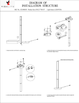
5
Finished installation - sensor pre-wired for plug-and-play, internal wiring diagram shown
Screw in hook and tighten
lock screw. Base is 1/2” NPT.
1
Hang xture and lock hook
screw to secure.
2
Turn o power, connect AC
wire. Black wire to L, white
wire to N, green wire to GND.
3
For sensor installation: Remove cover cap. Twist in sensor.
4
Sensor Installation
Fixture
To access dimming leads, pre-wired sensor
connection must be severed.

Albeo® ARC Series Installation Guide
LED.com
© 2023 Current Lighting Solutions, LLC. All rights reserved. Information and specifications subject to change
without notice. All values are design or typical values when measured under laboratory conditions.
Page 3 of 7
(Rev 05/17/23)
ALB086-Albeo-ARC-Series-Round-High-Bay-IP65-Installation-Guide_R01
Optional: Secure tether to the
xture
6
9
Optional: Secure refractor to
the xture
7
Optional: Secure wireguard to
xture
Optional: Secure drop lens to
refractor
8
Option: Connecting with 0-10V Dimmer
Fixture with sensor.
1
Cut the dimming wire which has been
connected with sensor base and driver.
2

Albeo® ARC Series Installation Guide
LED.com
© 2023 Current Lighting Solutions, LLC. All rights reserved. Information and specifications subject to change
without notice. All values are design or typical values when measured under laboratory conditions.
Page 4 of 7
(Rev 05/17/23)
ALB086-Albeo-ARC-Series-Round-High-Bay-IP65-Installation-Guide_R01
Pull out the dimming wire and peel o the
jacket for appropriate length
3
Connect the dimming wires with other
dimmer or sensor. Gray wire to DIM-, Purple
wire to DIM+, Pink wire to sensor input.
Note: the pink wire can only connect with 12V
sensor. If external sensor is not needed, pink
wire should be well isolated.
4

Albeo® ARC Series Installation Guide
LED.com
© 2023 Current Lighting Solutions, LLC. All rights reserved. Information and specifications subject to change
without notice. All values are design or typical values when measured under laboratory conditions.
Page 5 of 7
(Rev 05/17/23)
ALB086-Albeo-ARC-Series-Round-High-Bay-IP65-Installation-Guide_R01
Option: Battery Backup Installation
How to conrm the dimming wire version of high bay you received before installation:
High bays with Date Code
”21-46” and before come with
dimming wire version.
1
High bays with Date Code later than “21-46”come with below two
dimming wire versions.
2
Open or isolated
Tighten the hooks. Fix the junction box via the
lower hook.
In a visible location on the xture, attach the
label: “ASSEMBLE PART YH27FA-40WL, ONLY
WITH PART ARC014abccQVddAQe,ARC021abc-
cQVddAQe , ARC028abccQVddAQe,ARC033abc-
cQVddAQe.” This label is provided together with
this instruction sheet.
1
3
Connect the input wire of backup battery into
the junction box via the gray port, then
tighten the nut. Tighten the screws for
securing both hooks.
Cut the dimming wire that was connected with
xture sensor base and driver. Reserve as much
as possible the length of the dimming wire end
that is connected to the driver. Then open or
isolated another end that is connected with
sensor base.
2
4
Installation Steps
or

Albeo® ARC Series Installation Guide
LED.com
© 2023 Current Lighting Solutions, LLC. All rights reserved. Information and specifications subject to change
without notice. All values are design or typical values when measured under laboratory conditions.
Page 6 of 7
(Rev 05/17/23)
ALB086-Albeo-ARC-Series-Round-High-Bay-IP65-Installation-Guide_R01
Hook screw
Hook screw
(purple)
(pink/grey)
Warning: Make sure the 12v aux
wire was cut off in step "6" and
DO NOT connect 12V aux wire
(black-white/pink) into connector.
Battery system will be damaged if
12V aux wiring is connected.
AC WIRE
AC WIRE
Input wire
Input wire of
backup battary
of
backup battery
Fixture Input wire
Lamp AC Input Emergency power
output
Test
H-T
Test switch and
LED indicator Remote controller
Hang up the xture and the backup battery,
then tighten the hook screws.
Loosen the water proof connector, also the
screws in connector by Ph0 screwdriver, then
connect the dimming wires as below diagram.
Through the AC wire into the junction box;
Connect the input wire of backup battery with
AC wires, as below diagram.
5
7
9
Cut-o the 12V aux wire(black-white/pink) in
dimming cable which was connected with driver.
Open the junction box, connect xture’s input
wires with backup battery driver’s output wires.
Then fasten with wire nuts.
nstall the satety tether. Lock the junction box
cover and enter dierent mode by operate test
switch or remote controller.
6
8
10

Albeo® ARC Series Installation Guide
LED.com
© 2023 Current Lighting Solutions, LLC. All rights reserved. Information and specifications subject to change
without notice. All values are design or typical values when measured under laboratory conditions.
Page 7 of 7
(Rev 05/17/23)
ALB086-Albeo-ARC-Series-Round-High-Bay-IP65-Installation-Guide_R01
Backup conversion kit will go into backup mode if test switch is pressed when main supply is on, while it goes
into charging mode if test switch is not pressed. In backup mode, press the test switch for 3 seconds to
end the backup mode test.
Carry out 5S emergency mode test after pressing the test button once.
Press the H-T: button to enter hold test mode and press again to exit the test.
Red Led always on: charging mode or charging full.
Red o: main power o or discharging mode
Red ash: 0.5 second fast ash-represents failure.
2 second slow ash-represents low battery voltage and needs recharging.
Wiring Diagram
Notication for test switch, remote controller and LED indicator.
Pink/Grey
Test Switch:
Remote Controller Test:
LED Indicate:
/