GE current IND341 Installation guide

Type
Installation guide

GE current IND341 is a versatile and energy-efficient LED luminaire suitable for various indoor lighting applications. With lumen code options ranging from [84] to [B4], it provides a wide range of brightness levels to meet specific requirements. The luminaire is compatible with both 120V and 277V/347V electrical systems, allowing for flexible installation. Its durable construction and long lifespan make it a reliable choice for long-term use.

GE current IND341 is a versatile and energy-efficient LED luminaire suitable for various indoor lighting applications. With lumen code options ranging from [84] to [B4], it provides a wide range of brightness levels to meet specific requirements. The luminaire is compatible with both 120V and 277V/347V electrical systems, allowing for flexible installation. Its durable construction and long lifespan make it a reliable choice for long-term use.

Installation Guide
IND341 | GE2031-0483
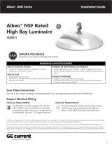
Lumination® LED Luminaire
LUS Series
BEFORE YOU BEGIN
Read these instructions completely and carefully.
WARNING / AVERTISSEMENT
RISK OF ELECTRIC SHOCK
Turn power o before inspection, installation or removal.
Properly ground electrical enclosure.
RISK OF FIRE
Follow all NEC and local codes.
Use only UL approved wire for input/output connections.
Minimum size 18AWG or 14AWG for continuous runs.
When using multi-branch wire circuits with a shared neutral,
do not operate any circuit with the neutral open. Also
ensure all neutral connections are secure before energizing
the circuit. An open neutral can cause an over-voltage
condition at the Luminaire power supply.
RISQUES DE DÉCHARGES ÉLECTRIQUES
Coupez l’alimentation avant d’inspecter, installer ou déplacer
le luminaire.
Assurez-vous de correctement mettre à la terre le boîtier
d’alimentation électrique.
RISQUES D’INCENDIE
Respectez tous les codes NEC et codes locaux.
N’utilisez que des ls approuvés par UL pour les entrées/sorties de
connexion. Taille minimum 18 AWG ou 14 AWG pour les rangées
continues.
Lorsque vous utilisez des circuits câblés à branches multiples avec
un neutre commun, ne mettez aucun circuit en service avec le neutre
ouvert. Assurezvous également que tous les raccords neutres soit
sécurisés avant de mettre le circuit sous tension. Un neutre ouvert
peut causer une condition de surtension à l’alimentation du luminaire.
Prepare Electrical Wiring
Electrical Requirements
The LED luminaire must be connected to the main
supply according to its ratings on the product label.
IMPORTANT
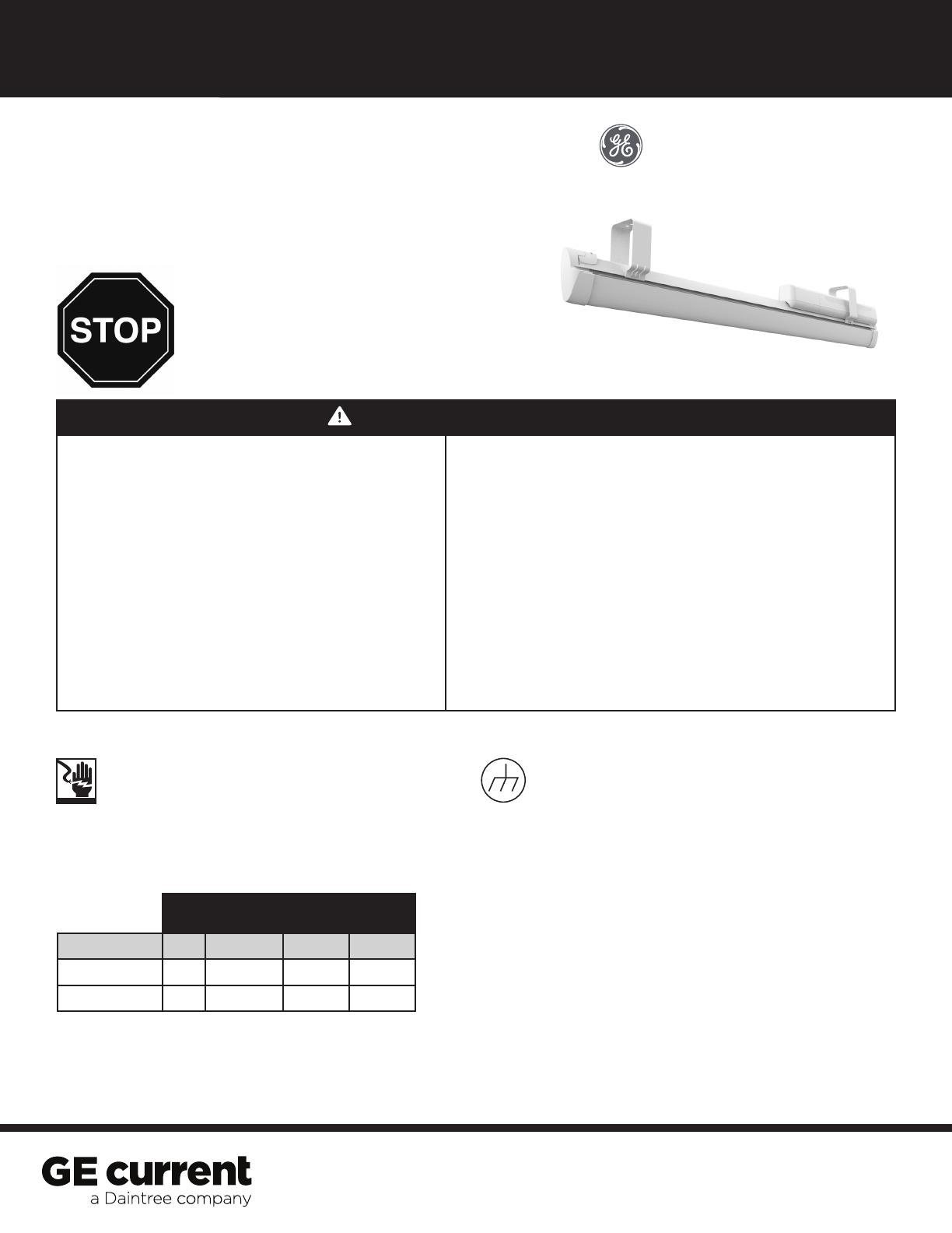
Maximum Length of Electrical Run
Grounding Instructions
The grounding and bonding of the overall system
shall be done in accordance with National Electric
Code (NEC) Article 600 and local codes.
Maximum driver current through connected xtures shall not
exceed 15A for lumen codes [42], [52], [62], [84], or [A0].
Maximum driver current through connected xtures shall not
exceed 12A for lumen codes [65], [85], [A3], [A7], [A1], [A2],
[B1] or [B4].
IMPORTANT NOTE: LUS series luminaires come in two versions: continuous units and independent units. A continuous
electrical run will consist of a number of continuous units up to a maximum current specied above. When installing
luminaires use clean gloves in order to avoid fouling the reective surface. To insure a clean xture, install the xture
with the plastic bag around the xture, and then remove plastic bag upon completion of any and all construction
related activity.
8ft Lumen Code
Voltage [84] [A02] [A2] [A3] [A7] [B1] [B4]
120V 192′ 160′ 80′ 60′
277V or 347V 400′ 320′ 188′ 132′
2
Lumination® Luminaire (LUS-Series) Installation Guide
Special Instructions for [TQ] and [TS] SKUs — Node Identication Label
1 Node identication label for the customer’s oor plan.
 2 Node identication label for the luminaire.
3 Daintree Node identication label installed
on luminaire back reector.
Installation of an Independent Luminaire
Prepare luminaire for installation
by loosening the knockout plate
screw and removing the knock-
out plate. Remove knockouts as
required and pass wires through
using UL listed strain reliefs.
Connect the green (ground), black
(line) and white (neutral) of the AC
line to corresponding colored wires
of the PSU using provided push-in
wire connectors or separate UL listed
wire nuts. Replace knockout plate
and tighten the screw.
OPTIONAL: Connect dimming pink
and violet wires to corresponding
colored xture wire using provided
push-in wire connectors or UL listed
wire nuts.
1 2
Wiring Diagrams
PSU (1–10V)
DALI/(1–10V)+
Line
Line (BLACK)
Neutral
Neutral (WHITE)
Ground (GREEN/YELLOW)
(1–10)+(PURPLE)
(1–10)(PINK)
Ground
PINK
PURPLE
RED
RED
BLUEBLUE
RED
Light
Engine
PSU 347V Transformer
Line BLACK
BLACK BLACKWHITE
BLUE
Neutral
Line
Neutral
(1–10V)
(1–10V)+
+
+
Line (BLACK)
Neutral (WHITE)
Ground (GREEN/YELLOW)
(1–10)+(PURPLE)
(1–10)(PINK)
1–10V Standard Wiring Diagram 1–10V 347V Wiring Diagram
3
Lumination® Luminaire (LUS-Series) Installation Guide
Installation of Brackets for Independent Luminaire
Maximum distance between suspension points shall not exceed the length of the luminaire.
Continuous run option: Row must begin with a rst xture that is suspended at both ends.
Use provided endcaps from starter kits to begin and terminate the row.
Suspension bracket — Type 2.
1
Upper
Place the bracket on the rails of
the heatsink so that the its hook
is around the upper part of the
heat sink.
Pull the bracket upward so
that the hooks of the bracket
are directly aligned with the
upper heatsink.
NOTE: Above is the correct
nal bracket installation on
upper heatsink.
NOTE: Slide the bracket along
the heatsink rails until desired
location is achieved.
Attach the suspension mechanism
to each bracket by following the
suspension kit instructions. Next,
suspend the continuous xture
from the ceiling.
Once each bracket is in the
appropriate location with respect
to the xture, secure the bracket
by tightening the pre-install screw
on either side of the bracket.
The screw needs to be touching
the upper heatsink.
 2  3  4
 5
4
Lumination® Luminaire (LUS-Series) Installation Guide
Installation of a Continuous Luminaire with Optional Branch Circuit
NOTE: For continuous luminaires, a starter kit must be purchased separately.
Follow the steps 1– 6 from the previous section, Installation of Independent Luminaires.
NOTE: For “BC” option code with additional branch circuit the PSU input wires (black and
white) will not be connected. These wires should be connected to the appropriate circuit
for each luminaire depending on the desired functionality.
1
 2
Circuit #1 connection: Connect the green ground),
black (line) and white (neutral) wires of AC line
to the corresponding colored wires of the starter
harness using push-in connectors.
Optional dimmer: Connect dimming control wires (pink & violet for 0-10V) to similarly colored xture wires
using the provided ideal connectors. Connect dimming control harness provided in the Starter Kit to connect to the
dimming leads.
NOTE: Optional branch circuit can be used for A/B switching by moving black and white PSU wires of “B” xtures onto
brown and brown/white wires.
On an additional circuit that requires its own neutral. Note that the brown/white is a neutral for the brown line.
For “EL” option SKU, see Emergency Light Supplement for wiring diagram.
For additional guidance please refer to NEC 2014 Section 410.64 Part C- Wiring Supplying Luminaires
connected together.
Circuit #2 connection: Connect the green (ground),
brown (line), and brown/white (neutral) wires of
the additional branch circuit to the green, white,
and black colored wires of the starter harness using
push-in connectors.
 2a
3
2b
Starter harness #1
Starter harness #2
5
Lumination® Luminaire (LUS-Series) Installation Guide
4
 6
 7  8  9
 5
Once the rst xture is wired correctly, including the
dimming leads, you can attach the second xture.
Slide the bridge lever, of the second xture being attached, completely to
the left or right.
When the bridge lever is
in the correct position,
connect both xtures by
attaching the second xture
to the bridge lever of the
rst xture.
Once both xtures are in
the correct position, slide
the bridge lever downwards
until it is pointing towards
the oor. The xtures are
now locked together.
Snap on the continuous
cap, provided in the kit.
Remove the PSU cover of the rst xture,
by pressing down on the circle and
pushing backward.
NOTE: For anti-snaking adjustments turn the bridge lever slightly left or right to change the angle between the
xtures until the desired alignment is reached. The oset average is 15mm with a maximum angle of 0.4 degrees.
6
Lumination® Luminaire (LUS-Series) Installation Guide
Pull the continuous wiring out of the rst xture to connect the power connectors of the through wiring harness.
For “BC” option luminaires the second branch circuit must be continued separately from the main circuit as shown
in section 10B.
Circuit #1 connections: Connect the black, white
and green wires from the preceding luminaire to the
same colored wire harness in the current luminaire
using the quick connectors.
NOTE: All unused wires must be capped.
Circuit #2 connections: Connect the brown (line)
and brown/white (neutral) wires of the current
luminaire’s wiring harness to the similar colored
wires from the preceding luminaire using the
push-in connectors.
NOTE: For additional guidance, please refer to
Wiring Diagram.
NOTE: PSU input wires in “BC” option luminaires
are not connected to either branch circuit by default.
Installer must select which branch to connect each
luminaire to by inserting the black and white PSU
wires into the appropriate branch circuit using the
push-in connectors provided.
10
 10a 10b
 11
 12
Replace the PSU cover by sliding it back into place until
it clips with the previous PSU cover.
Once the xtures are attached and all wires are connected, install
the end caps at both ends of the completed luminaire row, provided
in the starter kit.
WARNING
ANY ADDITIONAL WIRES
MUST BE CAPPED OFF
7
The Starter And Continuous Run Fixtures Connect In Rows
Installation of Wings
As the name implies, the Starter (if your product has such a choice) contains the beginning of the electrical connection.
This means that this xture has the only Power Drop.
The starter, when suspended, also is normally the only xture in the row with (2) suspension hangers.
The rest of the run may be suspended from a single hanger (positioned near the end where the next xture
will connect)
Starter
Follow the steps 1– 6 from the previous section, Installation of Independent Luminaires.
1
Snap the wings into place. First, wrap the wing around the
reector rails and then push them downwards. Add wings
to other sides of the xture.
Clip the wing retention
bracket, provided in the kit,
on top and in the middle
of the heatsink to hold the
wings in place.
 2  3
Lumination® Luminaire (LUS-Series) Installation Guide
Reector rails
Heat
Sink
Reector
8
Lumination® Luminaire (LUS-Series) Installation Guide
Remove endcaps using a
athead screwdriver.
For continuous conguration,
remove interconnecting bridge.
1Unclip old lens from light engine.
 2 Remove replacement lens from
packaging. Using a microber
cloth, wipe down the internal
cavity of the lens to remove
dust particles.
 3
4Line up and clip on the lens to
the light engine. Ensure that
the lens is lined ush with the
light engine.
 5 Locate the mounting tab
location. Clipping notches are
located 7.5 inches apart.
 6 Clip the lens into each mounting
tab. Needle nose pliers can be
used to clip in the lens. A click is
heard when the lens is clipped
into each tab. Swipe the lens by
hand to ensure proper clipping.
 7 Perform light up test to ensure
there are no dark spots
 8 Reinstall the endcaps onto
the xture. Ensure that the
caps are clipped properly
in place. For continuous
conguration, reinstall the
interconnecting bridge.
Replacement of Lens
9
Lumination® Luminaire (LUS-Series) Installation Guide
Replacement of Light Engine
Remove endcaps using a
athead screwdriver.
For continuous conguration,
remove interconnecting bridge.
1Unclip old lens from light engine.
 2 Push on tab and remove PSU
cover to gain access to wires.
 3
4Disconnect DC wires from
push-pin connectors.
Use tweezers if needed.
(Refer to wiring diagram
on the next page if needed)
5Using a athead driver,
pry the light engine o from
the heatsink. The connection
clips are located near both
extremities of the xture.
 6 Remove light engine and slide
out DC wires from PSU
compartment. Ensure that no
wires get tangled during
this process.
 7  8
Carefully remove replacement
light engine from packaging
and perform visual inspection
to ensure there is no damage.
Feed through the DC wires
from the light engine through
xture opening to the
PSU compartment.
 9 Line up light engine with
heatsink and mount it in place.
A click should be heard when
mounting light engine in place.
10
Replacement of Light Engine (cont.)
Lumination® Luminaire (LUS-Series) Installation Guide
Connect DC wires of light
engine to Power Supply Unit
(Refer to wiring diagram).
10 Ensure all wires are tucked
in properly inside PSU cavity
and close cover piece.
 11 Re-install the lens.
(Refer to lens replacement)
 12
13 Re-install the endcaps onto
the xture. Ensure that the
caps are clipped properly in
place. For continuous
conguration, re-install the
interconnecting bridge.
14 Perform light up test.
Fixture Fixture Fixture
BLACK
WHITE
BROWN
BROWN/WHITE
GREEN
VIOLET/WHITE
VIOLETDALI
DALI
Ground GREEN
VIOLET
PINK (18AWG)
010V
010V
Ground GREEN
VIOLET
PINK (18AWG)
010V
010V
Ground
Neutral
Line
Neutral
Circuit
#1
Circuit
#2
Line
0–10V EMBBDALI
BLACK BLACK from driver
BLACK from EMBB
WHITE
WHITE
BROWN
BROWN/WHITE
Neutral
Line
Neutral
Circuit
#1 Input
Power
Circuit
#2
Line Switch Line
Un-Switch Line
Neutral
Wiring Diagrams
11
Lumination® Luminaire (LUS-Series) Installation Guide
Replacement of Power Supply Unit
Push on tab and remove PSU
cover to gain access to wires.
1Remove both Hex head #8-18
screws securing the PSU.
 2 Using tweezers, disconnect
dimming wires and DC wires
from xture.
 3
4Remove knockout plate and
disconnect AC wires.
5Remove PSU from xture.
Ensure that the wires do not
get tangled.
 6 For EL option, or 85,A7 lumen
or 84, A0, A2 lumen with 347V
options, remove metal casing
to gain access to driver.
 7  8
Remove replacement PSU from
packaging and perform visual
inspection. Ensure that there is
no damage to the wires.
Line up PSU and xate using
provided HEX head screws
and washers.
 9 Connect the AC wires to
the xture’s wires and close
the knockout plate.
(For continuous conguration,
connect the dimming wires to
the through wiring.)
(Refer to wiring diagram)
Product Title (XXX- Series) Installation Guide
www.gecurrent.com
© 2021 Current Lighting Solutions, LLC. All rights reserved. GE and the GE monogram are trademarks of
the General Electric Company and are used under license. Information provided is subject to change without
notice. All values are design or typical values when measured under laboratory conditions.
IND341 (Rev 02/02/22)
Replacement of Power Supply Unit (cont.)
Connect the DC wires to
the black and red wires of the
light engines.
10 Ensure all wires are tucked in
properly inside PSU cavity and
close cover piece.
 11 Perform light up test.
 12
Lumination® Luminaire (LUS-Series) Installation Guide
Troubleshooting
Symptom Solution
Luminaires will not turn on
Check that the color of the supply side wires match the color of the wires they are
connected to.
Check that all wire connectors are properly connected.
Verify that the input voltage is within specs.
If you are using any additional controls (i.e. dimming wires, motion sensors),
please also verify that those are working properly and that the unit is setup to interface
with the controllers.
Luminaire on through
wiring will not turn on
Check that the through wiring connector from the previous xture in the linear row
is fully engaged to the malfunctioning luminaire.
Continuous Luminaire run
not leveled
Reposition the suspension brackets as close to the end of the xture as possible.
This device complies with Part 15 of the FCC Rules. Operation is subject to the following two conditions: (1)This device
may not cause harmful interference, and (2)this device must accept any interference received, including interference that
may cause undesired operation. This Class [A] RFLD complies with the Canadian standard ICES-005. Ce DEFR de la classe
[A]est conforme à la NMB-005 du Canada.
Note: This equipment has been tested and found to comply with the limits for a Class A digital device, pursuant to part
15 of the FCC Rules. These limits are designed to provide reasonable protection against harmful interference when
the equipment is operated in a commercial environment. This equipment generates, uses, and can radiate radio frequency
energy and, if not installed and used in accordance with the instruction manual, may cause harmful interference to radio
communications. Operation of this equipment in a residential area is likely to cause harmful interference in which case
the user will be required to correct the interference at his own expense.
  • Page 1 1
  • Page 2 2
  • Page 3 3
  • Page 4 4
  • Page 5 5
  • Page 6 6
  • Page 7 7
  • Page 8 8
  • Page 9 9
  • Page 10 10
  • Page 11 11
  • Page 12 12

GE current IND341 Installation guide

Type
Installation guide

GE current IND341 is a versatile and energy-efficient LED luminaire suitable for various indoor lighting applications. With lumen code options ranging from [84] to [B4], it provides a wide range of brightness levels to meet specific requirements. The luminaire is compatible with both 120V and 277V/347V electrical systems, allowing for flexible installation. Its durable construction and long lifespan make it a reliable choice for long-term use.

Ask a question and I''ll find the answer in the document

Finding information in a document is now easier with AI