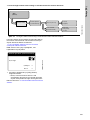
Grundfos Conex DIA-1 Installation And Operating Instructions Manual
- Type
- Installation And Operating Instructions Manual

Conex
®
DIA-1
Instrument amplifier and controller
Installation and operating instructions
GRUNDFOS INSTRUCTIONS
Page is loading ...

3
Table of contents
Conex
®
DIA-1
English (GB)
Installation and operating instructions. . . . . . . . . . . . . . . . . . . . . . . . . . . . . . . . . 4
Deutsch (DE)
Montage- und Betriebsanleitung . . . . . . . . . . . . . . . . . . . . . . . . . . . . . . . . . . . . 52
Español (ES)
Instrucciones de instalación y funcionamiento . . . . . . . . . . . . . . . . . . . . . . . . 100
Français (FR)
Notice d'installation et de fonctionnement. . . . . . . . . . . . . . . . . . . . . . . . . . . . 149
Ελληνικά (GR)
Οδηγίες εγκατάστασης και λειτουργίας . . . . . . . . . . . . . . . . . . . . . . . . . . . . . . 198
Italiano (IT)
Istruzioni di installazione e funzionamento . . . . . . . . . . . . . . . . . . . . . . . . . . . 254
Nederlands (NL)
Installatie- en bedieningsinstructies . . . . . . . . . . . . . . . . . . . . . . . . . . . . . . . . 303
Polski (PL)
Instrukcja montażu i eksploatacji . . . . . . . . . . . . . . . . . . . . . . . . . . . . . . . . . . 352
Português (PT)
Instruções de instalação e funcionamento . . . . . . . . . . . . . . . . . . . . . . . . . . . 401
Русский (RU)
Паспорт, Руководство по монтажу и эксплуатации . . . . . . . . . . . . . . . . . . 449
Slovensko (SI)
Navodila za montažo in obratovanje. . . . . . . . . . . . . . . . . . . . . . . . . . . . . . . . 498
Türkçe (TR)
Montaj ve kullanım kılavuzu . . . . . . . . . . . . . . . . . . . . . . . . . . . . . . . . . . . . . . 546
Declaration of conformity . . . . . . . . . . . . . . . . . . . . . . . . . . . . . . . . . . . . . . . . 596
Declaration of conformity RU . . . . . . . . . . . . . . . . . . . . . . . . . . . . . . . . . . . . . 597

English (GB)
4
English (GB) Installation and operating instructions
Original installation and operating instructions
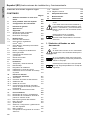
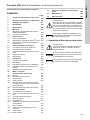
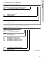
CONTENTS
Page
1. Symbols used in this document
1. Symbols used in this document
4
2. A few words in advance
5
3. Instrument settings
6
4. General information
8
5. Applications
8
6. Safety
8
6.1 Obligations of the owner/operations
manager
8
6.2 Avoidance of danger
8
7. Identification
8
7.1 Nameplate
8
7.2 Type key, Conex
®
DIA-1 controllers
9
7.3 Type key, Conex
®
DIA-1 preassembled
systems
9
8. Technical data
11
8.1 Design / enclosure class
11
8.2 General data
11
8.3 Electronic data and functions
11
8.4 Measuring ranges
13
8.5 Dimensions
13
9. Installation
14
9.1 Transport and storage
14
9.2 Unpacking
14
9.3 Installation requirements
14
9.4 Installation in control panel
14
9.5 Installation of wall-mounted enclosure
14
10. Commissioning / electrical
connections
15
10.1 Terminals
16
10.2 Power supply connection
18
10.3 Relay outputs
18
10.4 Current output
19
10.5 Connections of controller stop,
sample-water sensor and temperature
sensor
19
10.6 Connection of measuring cells
20
11. Operation
24
11.1 Control and display elements
24
11.2 Display elements during initial
commissioning
25
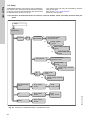
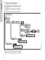
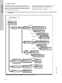
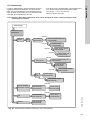
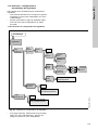
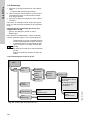
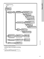
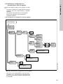
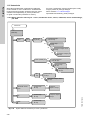
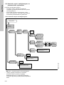
11.3 Software overview
26
11.4 Main menu
27
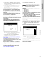
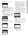
11.5 Setup
28
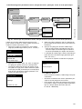
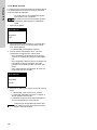
11.6 Selection, configuration and
parameterisation of the controller
34
11.7 "Alarm" menu
39
11.8 Checking the settings in the "service"
menu
41
11.9 Calibration
43
11.10 Manual operation
47
12. Fault finding
51
13. Maintenance
51
14. Disposal
51
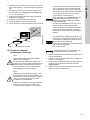
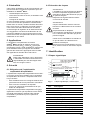
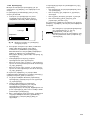
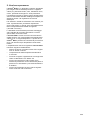
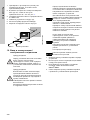
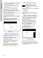
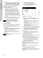
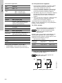
Warning
Prior to installation, read these installation
and operating instructions. Installation and
operation must comply with local
regulations and accepted codes of good
practice.
Note
These complete installation and operating
instructions are also available on
www.Grundfos.com.
Warning
If these safety instructions are not
observed, it may result in personal injury.
Caution
If these safety instructions are not
observed, it may result in malfunction or
damage to the equipment.
Note
Notes or instructions that make the job
easier and ensure safe operation.

English (GB)
5
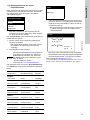
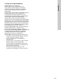
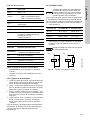
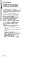
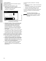
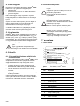
2. A few words in advance
The Conex
®
DIA-1 is a multipurpose device
designed to carry out high-precision measurements
and controls of pH value, redox potential, chlorine,
chlorine dioxide, ozone, hydrogen peroxide or
peracetic acid.
The integrated controller, the high-resolution
graphics display and the multilingual plain-text user
interface make complicated measuring and control
tasks in water chemistry much easier.
Just a few button inputs lead you to your goal.
The potentiostat helps save even more time, being
automatically matched to the various input variables.
The safety standard of the dosing process is raised
by the automatic open-circuit monitoring of the
current outputs.
The Conex
®
DIA-1 combines the functions of exact
chlorine measuring and automatic pH value
compensation in one single device. For this purpose,
the Conex
®
DIA-1 features a pH sensor interface
and an interface for external instrument amplifiers.
Properties of the Conex
®
DIA-1 measuring amplifier
and controller include the following:
• all control functions including PID and
continuous-action controls
• manual or automatic temperature compensation
• logbook function: chronological recording of
calibration values with date and time
• user coding function as a means of protection
against access by unauthorised persons and for
system administration
• error message function for indication of
non-functioning sensors.

English (GB)
6
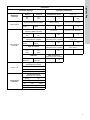
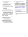
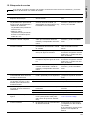
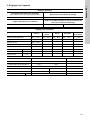
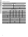
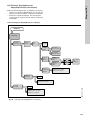
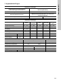
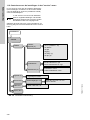
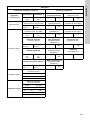
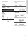
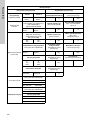
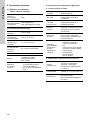
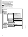
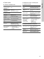
3. Instrument settings
General settings
Control of cleaning motor
(with measuring cell type AQC-D1/-D11)
Dosing time monitoring
Yes:_ No:_ Yes:_ No:_
Sample-water deficiency sensor
Maximum dosing time at constant load of 100 % of
dosing capacity
On:_ Off:_ sec.
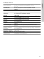
Parameter settings
Chlorine
Chlorine
dioxide
Ozone Peroxide
Peracetic
acid
Temperature measurement Yes:_ No:_ Yes:_ No:_ Yes:_ No:_ Yes:_ No:_ Yes:_ No:_
Compensation of temperature Yes:_ No:_ Yes:_ No:_ Yes:_ No:_ Yes:_ No:_ Yes:_ No:_
pH measurement Yes:_ No:_
Compensation of pH value Yes:_ No:_
Measuring cell type
Measuring range mg/l (ppm) - - - - -
Sensor slope µA/ppm
Current output mA-----
pH Redox
Temperature measurement Yes:_ No:_ Yes:_ No:_
Temperature compensation Yes:_ No:_
Measuring cell type
Measuring range pH - -
Slope mV/pH
Current output mA - -

English (GB)
7
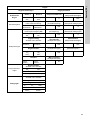
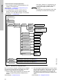
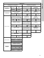
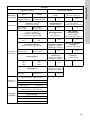
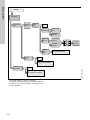
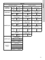
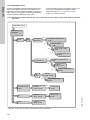
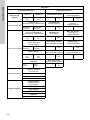
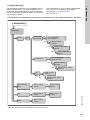
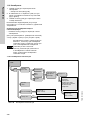
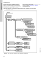
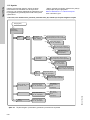
Controllers
Controller settings Controller parameters
Switching
controller
Relay 1 Relay 2 Proportional band
Min. pulse width
(3-pos. crtl.)
On:_
Off:_
On:_
Off:_
%sec.
Limit contact
Switching direction
Downward/upward violation
Reset time TN
(PI/PID-control)
Constant load
(two-pos.-/cont. controller)
Downwd.
Upwd.
Downwd.
Upwd.
sec. %
Two-position
controller
interpulse period (PP) or pulse
frequency (PF) controller
Deriv. action TV
(PI-control)
Max. dosing rate
(two-pos.-/cont. controller)
PP:_
PF:_
PP:_
PF:_
sec. %
Control direction
Downward or upward
Pulse-interp. interval
(interpulse period controller)
Motor runtime
(3-pos. crtl.)
Downwd.:_
Upwd.:_
Downwd.:_
Upwd.:_
sec. sec.
Type of control
Min. operation time
(interpulse period controller)
Hysteresis
(limit contact)
P:_
PI:_
PID:_
P:_
PI:_
PID:_
sec.
Setpoint
Max. frequency
(interpulse period controller)
Internal:_
External:_
Internal:_
External:_
Hz
3-pos. crtl.
Type of control
Downward or upward
Down:_ Up:_
Setpoint
Internal:_ External:_
Continuous
controller
Control direction
Downward or upward
Down:_ Up:_
Type of control
P:_ PI:_ PID:_
Setpoint
Internal:_ External:_

English (GB)
8
4. General information
These installation and operating instructions
contain all information important for users of the
Conex
®
DIA-1:
• technical data
• instructions on commissioning, use and
maintenance
• safety information.
Should you require further information or should you
encounter problems that are not handled in sufficient
depth in this manual, please contact Grundfos.
We shall be pleased to support you with our
comprehensive know-how in the fields of measuring
and control technology as well as water treatment.
We always welcome suggestions on how to optimise
our installation and operating instructions to satisfy
our customers.
5. Applications
The Conex
®
DIA-1 instrument amplifier and
controller is suitable for measuring chlorine (Cl
2
),
chlorine dioxide (ClO
2
), ozone (O
3
), hydrogen
peroxide (H
2
O
2
), peracetic acid, pH or redox
potential and for controlling these variables using
appropriate actuators within the applications
described in this manual.
6. Safety
6.1 Obligations of the owner/operations
manager
The owner/operations manager must ensure that
persons working with the Conex
®
DIA-1 instrument
amplifier and controller fulfil these requirements:
• They are acquainted with the regulations
concerning working safety and accident
prevention.
• They have been trained in use of the device.
• They have read and understood the warning
information and handling symbols.
The owner/operations manager is also responsible
for ensuring that this manual is kept in the immediate
vicinity of the device and is always available for the
operating personnel.
6.2 Avoidance of danger
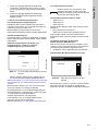
7. Identification
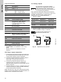
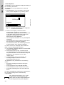
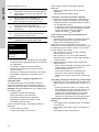
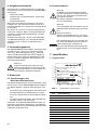
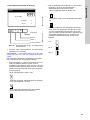
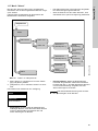
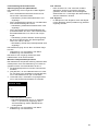
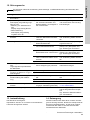
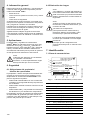
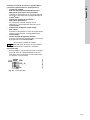
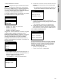
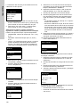
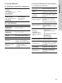
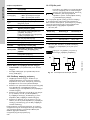
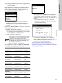
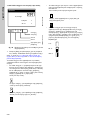
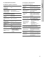
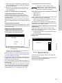
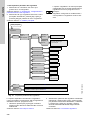
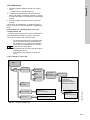
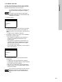
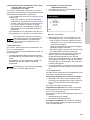
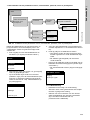
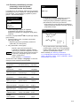
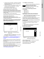
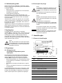
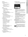
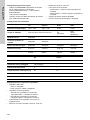
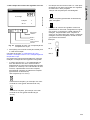
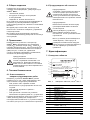
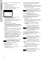
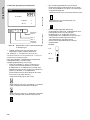
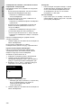
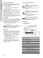
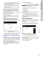
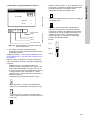
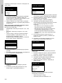
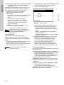
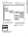
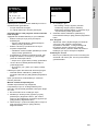
7.1 Nameplate
Fig. 1 Nameplate, Conex
®
DIA-1
Warning
Other applications are not approved and
not permitted. Grundfos cannot be held
liable for any damage resulting from
incorrect use.
Warning
Installation and connection of the device
and the associated supplementary
components must only be carried out by
authorised personnel!
The local safety regulations must be
observed!
Warning
Switch off the power supply before
connecting the power supply cable and
relay contacts!
Do not dismantle the device!
Maintenance and repair must only be
carried out by authorised personnel!
Caution
The mounting location must be selected so
that the housing is not subjected to
mechanical loading.
Check that all settings are correct before
starting up the device!
TM04 0332 0408
Pos. Description
1 Type designation
2 Model
3 Product name
4 Voltage [V]
5 Frequency [Hz]
6 Product number
7 Country of origin
8 Year and week of production
9 Marks of approval, CE mark, etc.
10 Power consumption [VA]
11 Enclosure class
12 Serial number
DIA-1-A D1-X-AU-X-QS-T, W-G
314-331-10000
S/N: 07/85229
Conex DIA-1 pre-assembled
230/240V 50/60Hz, 25 VA, IP 65
4.00 bar
96698140P1107480785229
1
2
3
4
5
6
7
811
12
13
910

English (GB)
9
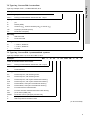
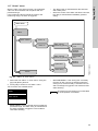
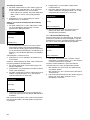
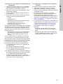
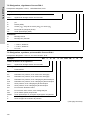
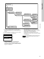
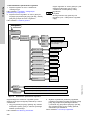
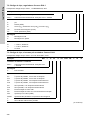
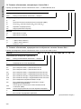
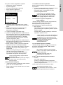
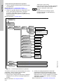
7.2 Type key, Conex
®
DIA-1 controllers
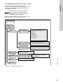
Type key example: DIA-1, 1-P/R/D/HP/PA/F, W-G
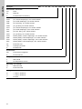
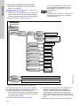
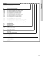
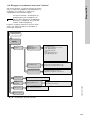
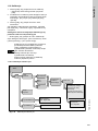
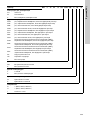
7.3 Type key, Conex
®
DIA-1 preassembled systems
Type key example: DIA-1-A, D1-X-AU-X-QS-T, W-G
Example: DIA -1 1-P/R/D/HP/PA/F -W -G
Measuring amplifier and controller
DIA-1 Dosing Instrumentation Advanced with 1 input
Input parameter 1
PpH
R Redox (ORP)
D Chlorine (Cl
2
), chlorine dioxide (ClO
2
) or ozone (O
3
)
HP Hydrogen peroxide (H
2
O
2
)
PA Peracetic acid (PAA)
Mounting
W Wall-mounted
P Panel-mounted
Voltage
G 1 x 230 V, 50/60 Hz
H 1 x 120 V, 50/60 Hz
I24 VDC
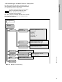
Example: DIA -1 -A D1 -P -PT -PCB -QS -T W -G
Units for measurement and control
DIA-1 Dosing Instrumentation Advanced, with 1 input
Assembly
A Preassembled
Cell type
D1 Pressure-proof, with cleaning motor
D11 Pressure-proof, with cleaning motor
D2 Pressure-proof, with hydro-mechanical cleaning
D12 Pressure-proof, with hydro-mechanical cleaning
D3 Pressureless, with hydro-mechanical cleaning
D13 Pressureless, with hydro-mechanical cleaning
D4 For total chlorine measurement
D5 For free chlorine measurement with buffer dosing
P/R pH or redox (ORP) only
PA/HP Peracetic acid or hydrogen peroxide only
P With pressure retention valve
X Without pressure retention valve
(to be continued)

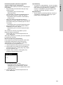
English (GB)
10
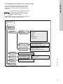
Example: DIA -1 -A D1 -P -PT -PCB -QS -T W -G
Disinfection electrodes
AU Gold
PT Platinum
X No disinfection measuring
Other electrodes
PCB pH, ceramic diaphragm, incl. buffer solution
PTB pH, PTFE diaphragm, incl. buffer solution
PKB pH, KCl filling, incl. buffer solution
PGB pH, gel filling incl. buffer solution
PCX pH, ceramic diaphragm, excl. buffer solution
PTX pH, PTFE diaphragm, excl. buffer solution
PKX pH, KCL filling, excl. buffer solution
PGX pH, gel filling, excl. buffer solution
RCB Redox (ORP), ceramic diaphragm, incl. buffer solution
RTB Redox (ORP), PTFE diaphragm, incl. buffer solution
RCX Redox (ORP), ceramic diaphragm, excl. buffer solution
RTX Redox (ORP), PTFE diaphragm, excl. buffer solution
PA Peracetic acid
HP Hydrogen peroxide
X No electrode
Flow sensor
QS Flow sensor integrated
X No flow sensor
Temperature sensor
T With Pt100
X No temperature sensor
Mounting of controller
W Wall-mounted
P Panel-mounted
Voltage
G 1 x 230 V, 50/60 Hz
H 1 x 120 V, 50/60 Hz
I24 VDC

English (GB)
11
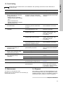
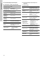
8. Technical data
8.1 Design / enclosure class
8.2 General data
8.3 Electronic data and functions
8.3.1 Electronics
8.3.2 Functions of the instrument amplifier
Wall-mounted
enclosure
including built-in
potentiostat
IP65
Control panel
enclosure
including separate
potentiostat
IP54 (front) /
IP65 (sensor interface)
Input power Approximately 15 VA
Permissible
ambient
temperature
0 °C to +45 °C
Permissible
storage
temperature
-20 °C to +65 °C
Maximum relative
humidity
90 % (non-condensing)
Weight 2 kg
Enclosure
Plastic (control panel
enclosure: noryl,
wall-mounted
enclosure: ABS)
Power supply
versions
• 230/240 V (50/60 Hz)
(standard model)
• 115/120 V (50/60 Hz)
• 24 VDC
Electronics 16-bit microprocessor
Display
High-resolution graphics LCD
with background light
Potential-free relay
outputs
1 alarm relay, 2 controller
relays (250 V/6 A, maximum
550 VA)
Signal inputs
Controller stop; external
setpoint / external pH value
0/4 to 20 mA; sample-water
deficiency sensor
Signal outputs
4 analog outputs 0/4 to
20 mA, freely adjustable,
maximum load 500 Ω
Freely adjustable
analog outputs for
measured values
• Chlorine, chlorine dioxide,
ozone, peroxide, peracetic
acid
• pH, redox (ORP)
• Temperature
• Continuous control
(0/4 to 20 mA)
Display mode
Measured-value display:
measured value with its unit,
temperature display:
in °C or °F
Temperature
compensation
Manual or automatic with
Pt100 (-5 °C to +120 °C)
Calibration
Manual or with automatic
recognition of buffer solution

English (GB)
12
8.3.3 Controller functions
Control functions
Limit contact, two-position
controller (P, PI, PID),
three-position step controller
(PI), continuous controller
(P, PI, PID)
Limiting value
0 to 100 % of full-scale value
(only with limit contact),
adjustable in the unit of the
measured value
Setpoints
0 to 100 % of the measuring
range, adjustable in the unit
of the measured value
Proportional band 0.1 to 3000 %
Reset time
1 to 3000 seconds, resolution
1 second
Derivative action
time
1 to 1000 seconds, resolution
1 second
Minimum pulse
length
0.1 to 10.0 seconds,
resolution 0.1 second (only
with three-position step
controller)
Minimum operating
time
0.1 to 10 seconds (only with
interpulse period controller)
Interpulse period
1 to 100 seconds (only with
interpulse period controller)
Maximum pulse
frequency
1 to 180 pulses per minute
(only with pulse frequency
controller)
Hysteresis
0 to half of the measuring
range, adjustable in the unit
of the measured value
Constant load
0 to 50 % (only with interpulse
period controller, pulse
frequency controller or
continuous controller)
Maximum dosing
flow
Base load dosing up to 100 %
of full-scale value (only with
interpulse period controller or
pulse frequency controller)
Motor runtime
10 to 240 seconds, resolution
1 second (only with
three-position step controller)
Effective direction
Can be set to upward or
downward
Control relays
Can be set to pulse-interpulse
or pulse frequency control

English (GB)
13
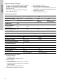
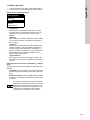
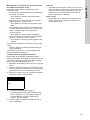
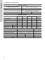
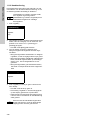
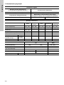
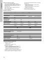
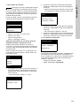
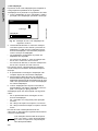
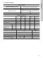
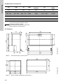
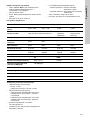
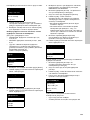
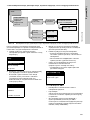
8.4 Measuring ranges
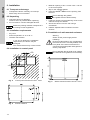
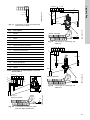
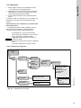
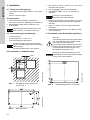
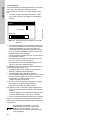
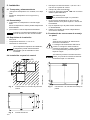
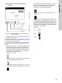
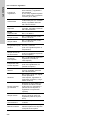
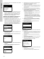
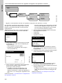
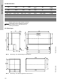
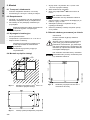
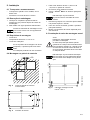
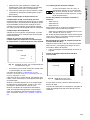
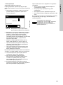
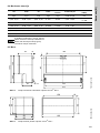
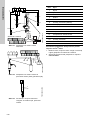
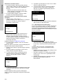
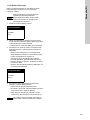
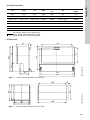
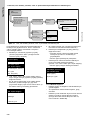
8.5 Dimensions
Fig. 2 Wall-mounted enclosure Conex
®
DIA-1
Fig. 3 Control panel enclosure Conex
®
DIA-1
CI
2
CIO
2
O
3
H
2
O
2
Peracetic
acid
pH
Redox
(ORP)
mg/l mg/l mg/l mg/l mg/l pH mV
0.00 - 0.50 0.00 - 0.50 0.00 - 0.50 0-100 0-100 0.00 - 14.00 -1500 to +1500
0.00 - 1.00 0.00 - 1.00 0.00 - 1.00 0-500 0-500 2.00 - 12.00 0-1000
0.00 - 2.00 0.00 - 2.00 0.00 - 2.00 0-1000 0-1000 5.00 - 9.00
0.00 - 5.00 0.00 - 5.00 0.00 - 5.00 0-2000 0-2000
0.00 - 10.00 0.00 - 10.00
0.00 - 20.00
Note
With the additional menu option "others",
the measuring range can be set to any
range within the limits listed above.
TM03 6687 4506
59
125
84
59.5
184.5
212
198
10
145
27
110
180
Ø 4.5
TM03 6688 4506
90
96
96
166
90
158
90
18

English (GB)
14
9. Installation
9.1 Transport and storage
• Transport the device carefully, do not drop!
• Store at dry and cool location.
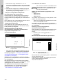
9.2 Unpacking
1. Check the device for damage.
Install as soon as possible after unpacking.
2. Do not install or connect damaged devices!
9.3 Installation requirements
• Dry room
• Room temperature: 0 °C to 45 °C
• Vibration-free location.
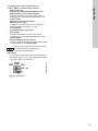
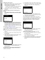
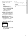
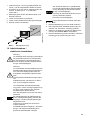
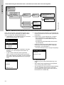
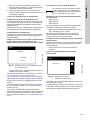
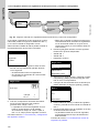
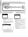
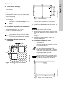
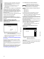
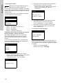
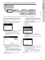
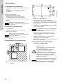
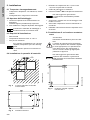
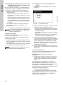
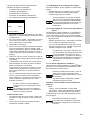
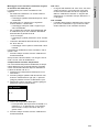
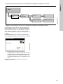
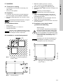
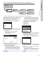
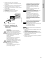
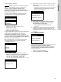
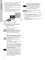
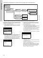
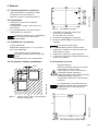
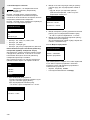
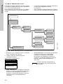
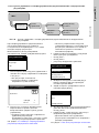
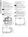
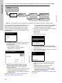
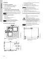
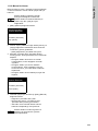
9.4 Installation in control panel
Fig. 4 Control panel enclosure Conex
®
DIA-1
Fig. 5 Sensor interface
1. Make an opening of 92 + 0.8 mm x 92 + 0.8 mm
in the control panel.
2. Slip on the supplied gasket.
3. Insert the Conex
®
DIA-1 into the opening from
the front.
1. Hook the clamps into the tightening cones on the
sides at the top and bottom.
2. Secure the device from the rear using a
screwdriver.
3. Install a separate sensor interface near the
sensors.
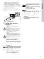
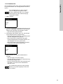
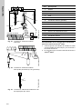
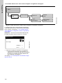
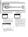
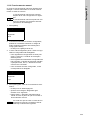
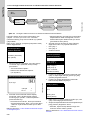
9.5 Installation of wall-mounted enclosure
Fig. 6 Wall-mounted enclosure Conex
®
DIA-1
Note
Retain the packing material or dispose of it
according to local regulations.
Caution
If you do not observe the installation
requirements, the device may be
damaged!
The measurements may not be correct!
TM03 6689 4506TM03 6690 4506
92
+0.8
92
+0.8
> 20
> 20
Caution
Do not damage the gasket!
The gasket must be fitted exactly!
Warning
Switch off the power supply before
installing!
Enclosure class IP65 is only guaranteed if
the terminal cover is correctly sealed, if the
front panel of the terminal enclosure is
closed and the appropriate cable glands or
dummy caps fitted.
Caution
Do not damage the terminal cover gasket!
The terminal cover gasket must fit exactly!
TM03 6691 4506
198
145
27
10.5

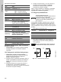
English (GB)
15
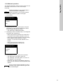
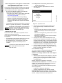
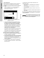
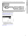
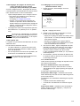
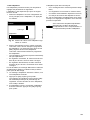
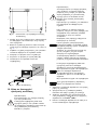
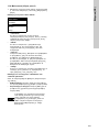
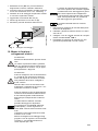
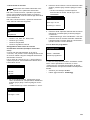
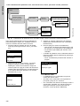
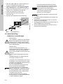
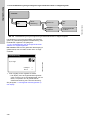
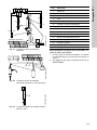
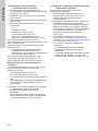
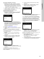
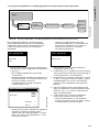
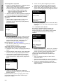
1. Drill three holes (8 mm) as shown in the
diagram, and insert the supplied dowels.
2. Screw the screw (A) into the top centre dowel
until it projects by approximately 1 cm. See fig. 7.
3. Loosen the fastening screws of the front panel,
and remove the front panel.
4. Hang the instrument onto the screw (A).
5. Tighten the instrument with the two screws (B).
6. Mount the front panel of the enclosure.
Fig. 7 Mounting drawing
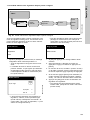
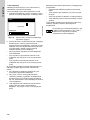
10. Commissioning / electrical
connections
1. Remove the terminal cover on the front of the
device.
2. Use the appropriate cable feedthroughs and
tighten the screws carefully.
3. Connect the cables used to the terminals
according to the Conex
®
DIA-1 terminal
assignment.
4. Close the terminal cover again with correctly
positioned gasket.
TM03 6692 4506
Warning
Switch off the power supply before
installing!
Enclosure class IP65 is only guaranteed
with the front panel of the terminals
enclosure closed and with appropriate
cable glands or dummy caps.
Warning
Switch off the power supply before
connecting the power supply cable and the
relay contacts! For safety reasons, the
protective conductor must be connected
correctly!
Observe the local safety regulations!
Protect the cable connections and plugs
against corrosion and moisture.
Caution
Before connecting the power supply cable,
check that the supply voltage specified on
the nameplate corresponds to the local
conditions!
An incorrect supply voltage may destroy
the device!
To guarantee electromagnetic compatibility
(EMC), the input and current output cables
must be screened.
Connect the screening to the screen
ground on one side.
Refer to the wiring diagram! Route the
input, current output and power supply
cables in separate cable channels.
B
B
A
Caution
Enclosure class IP65 is only guaranteed if
the terminal cover is correctly sealed! Do
not damage the gasket on the terminal
cover!
The gasket on the terminal cover must be
positioned precisely!
Do not damage the gasket!
Note
Unused terminals must remain open.

English (GB)
16
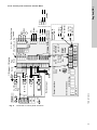
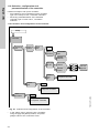
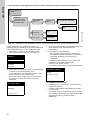
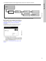
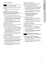
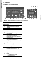
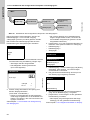
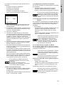
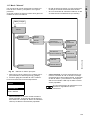
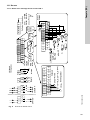
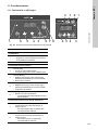
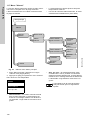
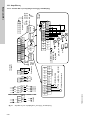
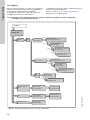
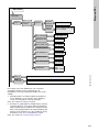
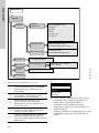
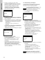
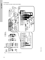
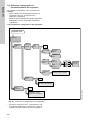
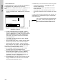
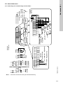
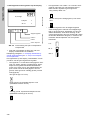
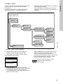
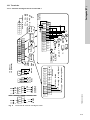
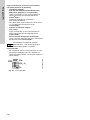
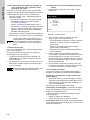
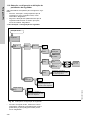
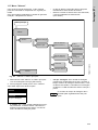
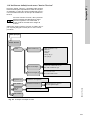
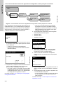
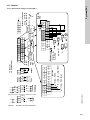
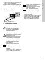
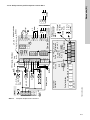
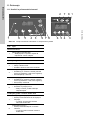
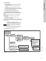
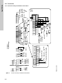
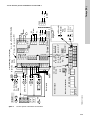
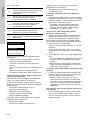
10.1 Terminals
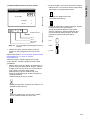
10.1.1 Wall-mounted enclosure Conex
®
DIA-1
Fig. 8 Terminals of wall-mounted enclosure
TM03 6693 4506
15
17 19 21 23 25
27
29 31 33 35
3634323028262422201816
15 17 19 21 23 25 27 29 31 33 35
3634323028
262422201816
37 38 39 40 41 42
37 =
38 = M
15 17
19
21 23 25 27 29 31 33 35
3634323028262422201816
PAA
H
2
O
2
15 (wh)
16 (br)
17 - 22
23 - 30
32,34,36
810
7
9
12
N.C.
N.O
.
11 13
12 14
21/22 = Pt 100
19 = + H
2
O, 20 = – H
2
O
17/18 =
1
2
3
4
Cl
2
,ClO
2
,O
3
,
H
2
O
2
,PAA
T /
+
–
mA
pH, mV, F
–
mA
mA
mA
33/35
mA
mA
39 = B/R
40 = G/C
mA
+
–
+
–
+
–
+
–
41/42 =
+/–
mV
–
pH
F
1
4
1
4
P1
P2
P2
P1
1 3 5
2 4 6
1 3 5
2 4 6
+ -
+ -
115/120 V
230/240 V
24 V/DC
NLPE
NLPE
Cells / electrodes
External
input
Outputs
Sensors
cells
Alarm
Relays
Sensors
(water)
Controller stop
Outputs
External
input
24 V/DC
115/120 V
230/240 V
15 (white)
16 (brown)

English (GB)
17
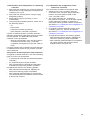
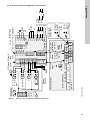
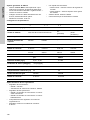
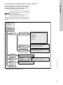
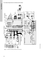
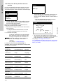
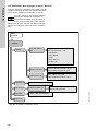
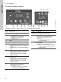
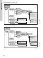
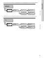
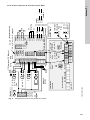
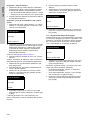
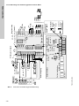
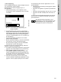
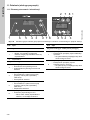
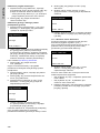
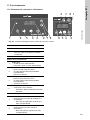
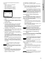
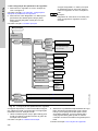
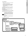
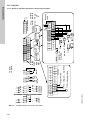
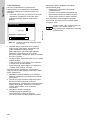
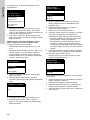
10.1.2 Control panel enclosure Conex
®
DIA-1
Fig. 9 Terminals of control panel enclosure
TM03 6979 4506
2/1
2/2
2/3
2/4
2
/1, 2/2
=
5/1 - 5/5
2/3 (+), 2/4 (–)
=
H
2
O
+
–
M B/R G/C
Pt 100
3/1 - 3/4
pH, mV, F
–
Cl
2
, ClO
2
,
O
3
,PAA,
H
2
O
2
pH, mV, F
–
3/1
3/2
3/3
3/4
4/1
4/2
4/3
4/4
7/1
7/2
7/3
N.C.
N.O.
1/1 (br), 1/2 (wh)
PAA
H
2
O
2
6/1
6/2
6/3
6/4
1
2
A 1/1 (br)
B 1/2 (wh)
PAA
H
2
O
2
A 2
/3 (+)
B 2 /4 (-)
H
2
O
1/11 1/13 4/1
1/12 1/14
4/3
4/2 4/4
3/1 3/3
3/2 3/4
B
A
1/11 -1/14
Pt 100
4/1 - 4/4
Conex DIA-1
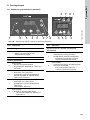
5/1
5/2
5/3
5/4
5/5
5/1
5/2
5/3
5/4
5/5
1
2
3
4
T
mA
Cl
2
, ClO
2
,
O
3
,H
2
O
2
,
PAA
pH, mV, F
–
mA
+
–
5/1 - 5/5
4
1
1/1
1/2
1/3
1/4
1/5
1/6
1/7
1/8
1/9
1/10
1/11
1/12
1/13
1/14
8/1
8/2
8/3
PE
N
L
8/1
8/2
8/3
-
+
115/120 V
230/240 V
24 V/DC
Controller stop
(water)
Relays
Alarm
Connection to
Conex
®
DIA-1
Cells
(water)
Cells:
Outputs
External input
Sensor interface
Cells / electrodes
Cells
Electrodes
Jumper
DIP
off on
24 V/DC
115/120 V
230/240 V
1/11 (brown), 1/2 (white)
1/1 (brown)
1/2 (white)

English (GB)
18
Legend of terminals
Control panel enclosure Conex
®
DIA-1
• Conex
®
DIA-1: for installation in the control
panel.
• Sensor interface: for installation near the
sensors.
10.2 Power supply connection
1. Control panel enclosure: Plug the plug strip into
the corresponding terminal strip at the rear side
of the device. Ensure correct orientation.
2. Connect the protective earth conductor (PE) to
terminal 5 (wall-mounted enclosure) or
terminal 8/1 (control panel enclosure).
3. Connect the neutral conductor (N) (or the -
conductor with 24 V version) to terminal 3
(wall-mounted enclosure) or terminal 8/2 (control
panel enclosure).
4. Connect phase (L1) (or the + conductor with 24 V
version) to terminal 1 (wall-mounted enclosure)
or 8/3 (control panel enclosure).
Switch the device on and off by switching the power
supply on and off accordingly. The device itself is not
equipped with a separate on/off switch.
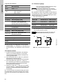
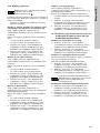
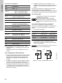
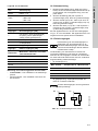
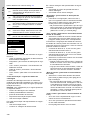
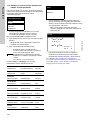
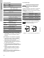
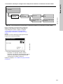
10.3 Relay outputs
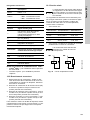
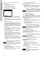
With inductive loads (also relays and contactors),
interference suppression is necessary. If this is not
possible, protect the relay contacts using a
suppressor circuit as described below.
• With AC voltage:
• With DC voltage: Connect the free-wheeling
diode in parallel to relay or contactor.
Fig. 10 Suppressor circuit, DC/AC
Pos. Description
Relays Relay 1 + 2
Alarm
Alarm relay
– N.O.: normally open
– N.C.: normally closed
Pt100 Temperature sensor
H
2
O Sample-water deficiency sensor
Stop Controller stop
Outputs Current outputs [mA]
1
Cl
2
(chlorine), ClO
2
(chlorine
dioxide), O
3
(ozone), H
2
O
2
(hydrogen peroxide) or PAA
(peracetic acid)
2 pH, mV (redox)
3 T: temperature
4 Continuous controller
Inputs External inputs [mA]
Electrodes
Measuring cells, electrodes and
single-rod measuring chains
M Measuring electrode
B/R Reference electrode
G/C Counter electrode
Earth
mV Redox electrode
Note
The connection of the relay outputs
depends on the application and the final
control elements used. Therefore the
connections described below should only
be considered as guidelines.
Current up to Capacitor C Resistor R
60 mA 10 nF, 275 V 390 Ω, 2 W
70 mA 47 nF, 275 V 22 Ω, 2 W
150 mA 100 nF, 275 V 47 Ω, 2 W
1.0 A 220 nF, 275 V 47 Ω, 2 W
Caution
Provide the relay outputs with a
corresponding backup fuse!
TM03 7209 2813
+
-
DC
R
C
AC

English (GB)
19
10.4 Current output
The current output can be set to one of the two
standard ranges "0-20 mA" or "4-20 mA", or it can be
freely adjusted.
• Connect the screen to earth (PE) at one end.
Output 1: chlorine, chlorine dioxide, ozone,
hydrogen peroxide or peracetic acid
This current output shows the displayed measured
value as an analog current signal.
Use of current signal for measured values:
• as input signal for another indicator
• as input signal for an external controller.
1. Connect the + conductor to terminal 23
(wall-mounted enclosure) or terminal 1/3 (control
panel enclosure).
2. Connect the - conductor to terminal 24
(wall-mounted enclosure) or terminal 1/4 (control
panel enclosure).
Output 2: pH, redox
This current output shows the displayed measured
value as an analog current signal.
Use of current signal for measured values:
• as input signal for another indicator
• as input signal for an external controller.
1. Connect the + conductor to terminal 25
(wall-mounted enclosure) or terminal 1/5 (control
panel enclosure).
2. Connect the - conductor to terminal 26
(wall-mounted enclosure) or terminal 1/4 (control
panel enclosure).
Output 3: temperature
This current output shows the temperature measured
by the optional temperature sensor.
Use of current signal for measured values:
• as input signal for another indicator.
1. Connect the + conductor to terminal 27
(wall-mounted enclosure) or terminal 1/6 (control
panel enclosure).
2. Connect the - conductor to terminal 28
(wall-mounted enclosure) or terminal 1/7 (control
panel enclosure).
Output 4: continuous control
This current output shows the calculated actuating
variable signal as an analog current signal.
Use of actuating variable signal:
• as input signal for a continuous final control
element.
1. Connect the + conductor to terminal 29
(wall-mounted enclosure) or terminal 1/8 (control
panel enclosure).
2. Connect the - conductor to terminal 30
(wall-mounted enclosure) or terminal 1/7 (control
panel enclosure).
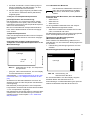
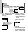
10.5 Connections of controller stop,
sample-water sensor and temperature
sensor
Connecting the controller stop
1. Connect the + conductor to terminal 17
(wall-mounted enclosure) or terminal 2/1 (control
panel enclosure).
2. Connect the - conductor to terminal 18
(wall-mounted enclosure) or terminal 2/2 (control
panel enclosure).
Connecting the sample-water sensor
Cable colours and marking: See connections of
measuring-cell types
AQC-D1/-D11/AQC-D2/-D12/AQC-D3/-D13.
1. Connect the + conductor to terminal 19
(wall-mounted enclosure) or terminal 2/3 (control
panel enclosure).
2. Connect the - conductor to terminal 20
(wall-mounted enclosure) or terminal 2/4 (control
panel enclosure).
Connecting the Pt100 temperature sensor
1. Connect the + conductor to terminal 21
(wall-mounted enclosure) or terminal 1/11
(control panel enclosure).
2. Connect the - conductor to terminal 22
(wall-mounted enclosure) or terminal 1/12
(control panel enclosure).
Caution
Make sure that the polarity of the current
output is correct!
Maximum load: 500
Ω
.
Note
When using measuring cell AQC-D2/-D12,
the water sensor must always be
connected and activated!

English (GB)
20
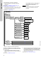
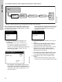
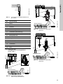
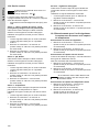
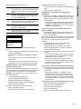
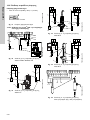
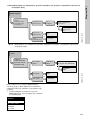
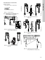
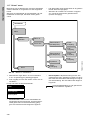
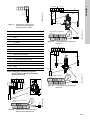
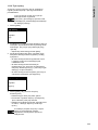
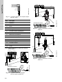
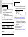
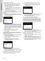
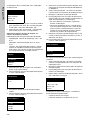
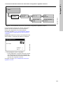
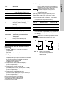
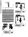
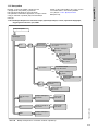
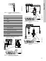
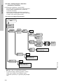
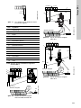
10.6 Connection of measuring cells
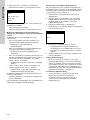
Jumper setting
• All cell types: position 1 (standard).
Fig. 11 Jumper setting
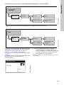
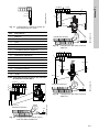
10.6.1 Connection of wall-mounted enclosure
Conex
®
DIA-1
Fig. 12 Connection to measuring cells
AQC-D1/AQC-D2/AQC-D3
Fig. 13 Connection to measuring cell
AQC-D11
Fig. 14 Connection to measuring cell
AQC-D12
Fig. 15 Connection to measuring cell
AQC-D13
Fig. 16 Connection to measuring cells
PAA (peracetic acid) / HP (peroxide)
TM03 6696 4506
TM03 5872 4112TM04 8642 4112
1
2
2
1:
Standard
7
5
1
37
38 39
40
41 42
6
12
4
1
15 17
19
21 23 25 27 29 31 33 35
3634323028262422201816
9, 10, 11
8
2
3
4
21
19
2220
4
12
11
1
1
38 40
39
9
8
10
TM04 8643 4112TM04 8644 4112TM03 6966 4112
7
10
9
1
6
2
37 38
39
40
8
21
19
2220
4
12
11
1
1
7
10
9
1
6
2
37 38
39
40
8
21
19
2220
2
12
11
COM
11
1
NC
12
15 17 19 21 23 25 27 29 31 33 35
3634323028262422201816
37 38 39 40 41 42
21
14 15

English (GB)
21
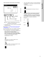
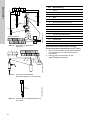
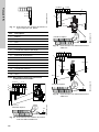
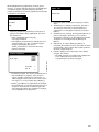
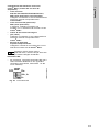
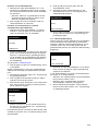
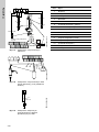
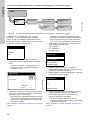
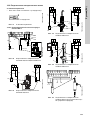
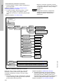
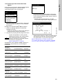
Fig. 17 Connection to single-rod measuring
chains for pH, redox
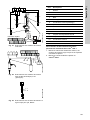
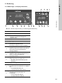
10.6.2 Connection of control panel enclosure
Conex
®
DIA-1
Fig. 18 Connection to measuring cells
AQC-D1/AQC-D2/AQC-D3
Fig. 19 Connection to measuring cell
AQC-D11
Fig. 20 Connection to measuring cell
AQC-D12
TM03 6967 4506
Pos. Description
1Brown
2White
3Black
4Blue
5 Screen
6 Outer conductor (screen)
7 Inner conductor
8 Reference electrode
9 Measuring electrode
10 Counter electrode
11 Pt100 temperature sensor
12 Water sensor
13 Outer conductor
14 Yellow
15 Green
TM03 5871 4212
37 38 39 40 41 42
7
13
+-
1/
11
1/
13
4/
1
1/
12
1/
14
4/
3
4/
2
4/
4
3/
1
3/
3
3/
2
3/
4
B
A
1
4
Conex
2/
3
2/
4
+
-
12
MB/RG/C
7
1
6
Pt 100
2
5
8
9, 10, 11
3
4
Sensor interface
TM04 8645 4112TM04 8646 4112
4
11
1
Pt 100
9
8
10
1/
11
1/
13
4/
1
1/
12
1/
14
4/
3
4/
2
4/
4
3/
1
3/
3
3/
2
3/
4
B
A
1
4
Conex
2/
3
2/
4
+
-
12
G/CM
B/R
Sensor interface
7
10
9
1
6
2
8
4
11
1
1/
11
1/
13
4/
1
1/
12
1/
14
4/
3
4/
2
4/
4
3/
1
3/
3
3/
2
3/
4
B
A
1
4
Conex
2/
3
2/
4
+
-
12
Pt 100G/CM
B/R
Sensor interface
Page is loading ...
Page is loading ...
Page is loading ...
Page is loading ...
Page is loading ...
Page is loading ...
Page is loading ...
Page is loading ...
Page is loading ...
Page is loading ...
Page is loading ...
Page is loading ...
Page is loading ...
Page is loading ...
Page is loading ...
Page is loading ...
Page is loading ...
Page is loading ...
Page is loading ...
Page is loading ...
Page is loading ...
Page is loading ...
Page is loading ...
Page is loading ...
Page is loading ...
Page is loading ...
Page is loading ...
Page is loading ...
Page is loading ...
Page is loading ...
Page is loading ...
Page is loading ...
Page is loading ...
Page is loading ...
Page is loading ...
Page is loading ...
Page is loading ...
Page is loading ...
Page is loading ...
Page is loading ...
Page is loading ...
Page is loading ...
Page is loading ...
Page is loading ...
Page is loading ...
Page is loading ...
Page is loading ...
Page is loading ...
Page is loading ...
Page is loading ...
Page is loading ...
Page is loading ...
Page is loading ...
Page is loading ...
Page is loading ...
Page is loading ...
Page is loading ...
Page is loading ...
Page is loading ...
Page is loading ...
Page is loading ...
Page is loading ...
Page is loading ...
Page is loading ...
Page is loading ...
Page is loading ...
Page is loading ...
Page is loading ...
Page is loading ...
Page is loading ...
Page is loading ...
Page is loading ...
Page is loading ...
Page is loading ...
Page is loading ...
Page is loading ...
Page is loading ...
Page is loading ...
Page is loading ...
Page is loading ...
Page is loading ...
Page is loading ...
Page is loading ...
Page is loading ...
Page is loading ...
Page is loading ...
Page is loading ...
Page is loading ...
Page is loading ...
Page is loading ...
Page is loading ...
Page is loading ...
Page is loading ...
Page is loading ...
Page is loading ...
Page is loading ...
Page is loading ...
Page is loading ...
Page is loading ...
Page is loading ...
Page is loading ...
Page is loading ...
Page is loading ...
Page is loading ...
Page is loading ...
Page is loading ...
Page is loading ...
Page is loading ...
Page is loading ...
Page is loading ...
Page is loading ...
Page is loading ...
Page is loading ...
Page is loading ...
Page is loading ...
Page is loading ...
Page is loading ...
Page is loading ...
Page is loading ...
Page is loading ...
Page is loading ...
Page is loading ...
Page is loading ...
Page is loading ...
Page is loading ...
Page is loading ...
Page is loading ...
Page is loading ...
Page is loading ...
Page is loading ...
Page is loading ...
Page is loading ...
Page is loading ...
Page is loading ...
Page is loading ...
Page is loading ...
Page is loading ...
Page is loading ...
Page is loading ...
Page is loading ...
Page is loading ...
Page is loading ...
Page is loading ...
Page is loading ...
Page is loading ...
Page is loading ...
Page is loading ...
Page is loading ...
Page is loading ...
Page is loading ...
Page is loading ...
Page is loading ...
Page is loading ...
Page is loading ...
Page is loading ...
Page is loading ...
Page is loading ...
Page is loading ...
Page is loading ...
Page is loading ...
Page is loading ...
Page is loading ...
Page is loading ...
Page is loading ...
Page is loading ...
Page is loading ...
Page is loading ...
Page is loading ...
Page is loading ...
Page is loading ...
Page is loading ...
Page is loading ...
Page is loading ...
Page is loading ...
Page is loading ...
Page is loading ...
Page is loading ...
Page is loading ...
Page is loading ...
Page is loading ...
Page is loading ...
Page is loading ...
Page is loading ...
Page is loading ...
Page is loading ...
Page is loading ...
Page is loading ...
Page is loading ...
Page is loading ...
Page is loading ...
Page is loading ...
Page is loading ...
Page is loading ...
Page is loading ...
Page is loading ...
Page is loading ...
Page is loading ...
Page is loading ...
Page is loading ...
Page is loading ...
Page is loading ...
Page is loading ...
Page is loading ...
Page is loading ...
Page is loading ...
Page is loading ...
Page is loading ...
Page is loading ...
Page is loading ...
Page is loading ...
Page is loading ...
Page is loading ...
Page is loading ...
Page is loading ...
Page is loading ...
Page is loading ...
Page is loading ...
Page is loading ...
Page is loading ...
Page is loading ...
Page is loading ...
Page is loading ...
Page is loading ...
Page is loading ...
Page is loading ...
Page is loading ...
Page is loading ...
Page is loading ...
Page is loading ...
Page is loading ...
Page is loading ...
Page is loading ...
Page is loading ...
Page is loading ...
Page is loading ...
Page is loading ...
Page is loading ...
Page is loading ...
Page is loading ...
Page is loading ...
Page is loading ...
Page is loading ...
Page is loading ...
Page is loading ...
Page is loading ...
Page is loading ...
Page is loading ...
Page is loading ...
Page is loading ...
Page is loading ...
Page is loading ...
Page is loading ...
Page is loading ...
Page is loading ...
Page is loading ...
Page is loading ...
Page is loading ...
Page is loading ...
Page is loading ...
Page is loading ...
Page is loading ...
Page is loading ...
Page is loading ...
Page is loading ...
Page is loading ...
Page is loading ...
Page is loading ...
Page is loading ...
Page is loading ...
Page is loading ...
Page is loading ...
Page is loading ...
Page is loading ...
Page is loading ...
Page is loading ...
Page is loading ...
Page is loading ...
Page is loading ...
Page is loading ...
Page is loading ...
Page is loading ...
Page is loading ...
Page is loading ...
Page is loading ...
Page is loading ...
Page is loading ...
Page is loading ...
Page is loading ...
Page is loading ...
Page is loading ...
Page is loading ...
Page is loading ...
Page is loading ...
Page is loading ...
Page is loading ...
Page is loading ...
Page is loading ...
Page is loading ...
Page is loading ...
Page is loading ...
Page is loading ...
Page is loading ...
Page is loading ...
Page is loading ...
Page is loading ...
Page is loading ...
Page is loading ...
Page is loading ...
Page is loading ...
Page is loading ...
Page is loading ...
Page is loading ...
Page is loading ...
Page is loading ...
Page is loading ...
Page is loading ...
Page is loading ...
Page is loading ...
Page is loading ...
Page is loading ...
Page is loading ...
Page is loading ...
Page is loading ...
Page is loading ...
Page is loading ...
Page is loading ...
Page is loading ...
Page is loading ...
Page is loading ...
Page is loading ...
Page is loading ...
Page is loading ...
Page is loading ...
Page is loading ...
Page is loading ...
Page is loading ...
Page is loading ...
Page is loading ...
Page is loading ...
Page is loading ...
Page is loading ...
Page is loading ...
Page is loading ...
Page is loading ...
Page is loading ...
Page is loading ...
Page is loading ...
Page is loading ...
Page is loading ...
Page is loading ...
Page is loading ...
Page is loading ...
Page is loading ...
Page is loading ...
Page is loading ...
Page is loading ...
Page is loading ...
Page is loading ...
Page is loading ...
Page is loading ...
Page is loading ...
Page is loading ...
Page is loading ...
Page is loading ...
Page is loading ...
Page is loading ...
Page is loading ...
Page is loading ...
Page is loading ...
Page is loading ...
Page is loading ...
Page is loading ...
Page is loading ...
Page is loading ...
Page is loading ...
Page is loading ...
Page is loading ...
Page is loading ...
Page is loading ...
Page is loading ...
Page is loading ...
Page is loading ...
Page is loading ...
Page is loading ...
Page is loading ...
Page is loading ...
Page is loading ...
Page is loading ...
Page is loading ...
Page is loading ...
Page is loading ...
Page is loading ...
Page is loading ...
Page is loading ...
Page is loading ...
Page is loading ...
Page is loading ...
Page is loading ...
Page is loading ...
Page is loading ...
Page is loading ...
Page is loading ...
Page is loading ...
Page is loading ...
Page is loading ...
Page is loading ...
Page is loading ...
Page is loading ...
Page is loading ...
Page is loading ...
Page is loading ...
Page is loading ...
Page is loading ...
Page is loading ...
Page is loading ...
Page is loading ...
Page is loading ...
Page is loading ...
Page is loading ...
Page is loading ...
Page is loading ...
Page is loading ...
Page is loading ...
Page is loading ...
Page is loading ...
Page is loading ...
Page is loading ...
Page is loading ...
Page is loading ...
Page is loading ...
Page is loading ...
Page is loading ...
Page is loading ...
Page is loading ...
Page is loading ...
Page is loading ...
Page is loading ...
Page is loading ...
Page is loading ...
Page is loading ...
Page is loading ...
Page is loading ...
Page is loading ...
Page is loading ...
Page is loading ...
Page is loading ...
Page is loading ...
Page is loading ...
Page is loading ...
Page is loading ...
Page is loading ...
Page is loading ...
Page is loading ...
Page is loading ...
Page is loading ...
Page is loading ...
Page is loading ...
Page is loading ...
Page is loading ...
Page is loading ...
Page is loading ...
Page is loading ...
Page is loading ...
Page is loading ...
Page is loading ...
Page is loading ...
Page is loading ...
Page is loading ...
Page is loading ...
Page is loading ...
Page is loading ...
Page is loading ...
Page is loading ...
Page is loading ...
Page is loading ...
Page is loading ...
Page is loading ...
Page is loading ...
Page is loading ...
Page is loading ...
Page is loading ...
Page is loading ...
Page is loading ...
Page is loading ...
Page is loading ...
Page is loading ...
Page is loading ...
Page is loading ...
Page is loading ...
Page is loading ...
Page is loading ...
Page is loading ...
Page is loading ...
Page is loading ...
Page is loading ...
Page is loading ...
Page is loading ...
Page is loading ...
Page is loading ...
Page is loading ...
Page is loading ...
Page is loading ...
Page is loading ...
Page is loading ...
Page is loading ...
Page is loading ...
Page is loading ...
Page is loading ...
Page is loading ...
Page is loading ...
Page is loading ...
Page is loading ...
Page is loading ...
Page is loading ...
Page is loading ...
Page is loading ...
Page is loading ...
Page is loading ...
Page is loading ...
Page is loading ...
Page is loading ...
Page is loading ...
Page is loading ...
Page is loading ...
Page is loading ...
Page is loading ...
Page is loading ...
Page is loading ...
Page is loading ...
Page is loading ...
Page is loading ...
Page is loading ...
Page is loading ...
Page is loading ...
Page is loading ...
Page is loading ...
Page is loading ...
Page is loading ...
Page is loading ...
Page is loading ...
Page is loading ...
Page is loading ...
Page is loading ...
Page is loading ...
Page is loading ...
Page is loading ...
Page is loading ...
Page is loading ...
Page is loading ...
Page is loading ...
Page is loading ...
Page is loading ...
Page is loading ...
Page is loading ...
Page is loading ...
Page is loading ...
Page is loading ...
Page is loading ...
Page is loading ...
Page is loading ...
Page is loading ...
Page is loading ...
Page is loading ...
Page is loading ...
Page is loading ...
Page is loading ...
Page is loading ...
Page is loading ...
Page is loading ...
Page is loading ...
Page is loading ...
Page is loading ...
Page is loading ...
Page is loading ...
Page is loading ...
Page is loading ...
Page is loading ...
Page is loading ...
Page is loading ...
-
 1
1
-
 2
2
-
 3
3
-
 4
4
-
 5
5
-
 6
6
-
 7
7
-
 8
8
-
 9
9
-
 10
10
-
 11
11
-
 12
12
-
 13
13
-
 14
14
-
 15
15
-
 16
16
-
 17
17
-
 18
18
-
 19
19
-
 20
20
-
 21
21
-
 22
22
-
 23
23
-
 24
24
-
 25
25
-
 26
26
-
 27
27
-
 28
28
-
 29
29
-
 30
30
-
 31
31
-
 32
32
-
 33
33
-
 34
34
-
 35
35
-
 36
36
-
 37
37
-
 38
38
-
 39
39
-
 40
40
-
 41
41
-
 42
42
-
 43
43
-
 44
44
-
 45
45
-
 46
46
-
 47
47
-
 48
48
-
 49
49
-
 50
50
-
 51
51
-
 52
52
-
 53
53
-
 54
54
-
 55
55
-
 56
56
-
 57
57
-
 58
58
-
 59
59
-
 60
60
-
 61
61
-
 62
62
-
 63
63
-
 64
64
-
 65
65
-
 66
66
-
 67
67
-
 68
68
-
 69
69
-
 70
70
-
 71
71
-
 72
72
-
 73
73
-
 74
74
-
 75
75
-
 76
76
-
 77
77
-
 78
78
-
 79
79
-
 80
80
-
 81
81
-
 82
82
-
 83
83
-
 84
84
-
 85
85
-
 86
86
-
 87
87
-
 88
88
-
 89
89
-
 90
90
-
 91
91
-
 92
92
-
 93
93
-
 94
94
-
 95
95
-
 96
96
-
 97
97
-
 98
98
-
 99
99
-
 100
100
-
 101
101
-
 102
102
-
 103
103
-
 104
104
-
 105
105
-
 106
106
-
 107
107
-
 108
108
-
 109
109
-
 110
110
-
 111
111
-
 112
112
-
 113
113
-
 114
114
-
 115
115
-
 116
116
-
 117
117
-
 118
118
-
 119
119
-
 120
120
-
 121
121
-
 122
122
-
 123
123
-
 124
124
-
 125
125
-
 126
126
-
 127
127
-
 128
128
-
 129
129
-
 130
130
-
 131
131
-
 132
132
-
 133
133
-
 134
134
-
 135
135
-
 136
136
-
 137
137
-
 138
138
-
 139
139
-
 140
140
-
 141
141
-
 142
142
-
 143
143
-
 144
144
-
 145
145
-
 146
146
-
 147
147
-
 148
148
-
 149
149
-
 150
150
-
 151
151
-
 152
152
-
 153
153
-
 154
154
-
 155
155
-
 156
156
-
 157
157
-
 158
158
-
 159
159
-
 160
160
-
 161
161
-
 162
162
-
 163
163
-
 164
164
-
 165
165
-
 166
166
-
 167
167
-
 168
168
-
 169
169
-
 170
170
-
 171
171
-
 172
172
-
 173
173
-
 174
174
-
 175
175
-
 176
176
-
 177
177
-
 178
178
-
 179
179
-
 180
180
-
 181
181
-
 182
182
-
 183
183
-
 184
184
-
 185
185
-
 186
186
-
 187
187
-
 188
188
-
 189
189
-
 190
190
-
 191
191
-
 192
192
-
 193
193
-
 194
194
-
 195
195
-
 196
196
-
 197
197
-
 198
198
-
 199
199
-
 200
200
-
 201
201
-
 202
202
-
 203
203
-
 204
204
-
 205
205
-
 206
206
-
 207
207
-
 208
208
-
 209
209
-
 210
210
-
 211
211
-
 212
212
-
 213
213
-
 214
214
-
 215
215
-
 216
216
-
 217
217
-
 218
218
-
 219
219
-
 220
220
-
 221
221
-
 222
222
-
 223
223
-
 224
224
-
 225
225
-
 226
226
-
 227
227
-
 228
228
-
 229
229
-
 230
230
-
 231
231
-
 232
232
-
 233
233
-
 234
234
-
 235
235
-
 236
236
-
 237
237
-
 238
238
-
 239
239
-
 240
240
-
 241
241
-
 242
242
-
 243
243
-
 244
244
-
 245
245
-
 246
246
-
 247
247
-
 248
248
-
 249
249
-
 250
250
-
 251
251
-
 252
252
-
 253
253
-
 254
254
-
 255
255
-
 256
256
-
 257
257
-
 258
258
-
 259
259
-
 260
260
-
 261
261
-
 262
262
-
 263
263
-
 264
264
-
 265
265
-
 266
266
-
 267
267
-
 268
268
-
 269
269
-
 270
270
-
 271
271
-
 272
272
-
 273
273
-
 274
274
-
 275
275
-
 276
276
-
 277
277
-
 278
278
-
 279
279
-
 280
280
-
 281
281
-
 282
282
-
 283
283
-
 284
284
-
 285
285
-
 286
286
-
 287
287
-
 288
288
-
 289
289
-
 290
290
-
 291
291
-
 292
292
-
 293
293
-
 294
294
-
 295
295
-
 296
296
-
 297
297
-
 298
298
-
 299
299
-
 300
300
-
 301
301
-
 302
302
-
 303
303
-
 304
304
-
 305
305
-
 306
306
-
 307
307
-
 308
308
-
 309
309
-
 310
310
-
 311
311
-
 312
312
-
 313
313
-
 314
314
-
 315
315
-
 316
316
-
 317
317
-
 318
318
-
 319
319
-
 320
320
-
 321
321
-
 322
322
-
 323
323
-
 324
324
-
 325
325
-
 326
326
-
 327
327
-
 328
328
-
 329
329
-
 330
330
-
 331
331
-
 332
332
-
 333
333
-
 334
334
-
 335
335
-
 336
336
-
 337
337
-
 338
338
-
 339
339
-
 340
340
-
 341
341
-
 342
342
-
 343
343
-
 344
344
-
 345
345
-
 346
346
-
 347
347
-
 348
348
-
 349
349
-
 350
350
-
 351
351
-
 352
352
-
 353
353
-
 354
354
-
 355
355
-
 356
356
-
 357
357
-
 358
358
-
 359
359
-
 360
360
-
 361
361
-
 362
362
-
 363
363
-
 364
364
-
 365
365
-
 366
366
-
 367
367
-
 368
368
-
 369
369
-
 370
370
-
 371
371
-
 372
372
-
 373
373
-
 374
374
-
 375
375
-
 376
376
-
 377
377
-
 378
378
-
 379
379
-
 380
380
-
 381
381
-
 382
382
-
 383
383
-
 384
384
-
 385
385
-
 386
386
-
 387
387
-
 388
388
-
 389
389
-
 390
390
-
 391
391
-
 392
392
-
 393
393
-
 394
394
-
 395
395
-
 396
396
-
 397
397
-
 398
398
-
 399
399
-
 400
400
-
 401
401
-
 402
402
-
 403
403
-
 404
404
-
 405
405
-
 406
406
-
 407
407
-
 408
408
-
 409
409
-
 410
410
-
 411
411
-
 412
412
-
 413
413
-
 414
414
-
 415
415
-
 416
416
-
 417
417
-
 418
418
-
 419
419
-
 420
420
-
 421
421
-
 422
422
-
 423
423
-
 424
424
-
 425
425
-
 426
426
-
 427
427
-
 428
428
-
 429
429
-
 430
430
-
 431
431
-
 432
432
-
 433
433
-
 434
434
-
 435
435
-
 436
436
-
 437
437
-
 438
438
-
 439
439
-
 440
440
-
 441
441
-
 442
442
-
 443
443
-
 444
444
-
 445
445
-
 446
446
-
 447
447
-
 448
448
-
 449
449
-
 450
450
-
 451
451
-
 452
452
-
 453
453
-
 454
454
-
 455
455
-
 456
456
-
 457
457
-
 458
458
-
 459
459
-
 460
460
-
 461
461
-
 462
462
-
 463
463
-
 464
464
-
 465
465
-
 466
466
-
 467
467
-
 468
468
-
 469
469
-
 470
470
-
 471
471
-
 472
472
-
 473
473
-
 474
474
-
 475
475
-
 476
476
-
 477
477
-
 478
478
-
 479
479
-
 480
480
-
 481
481
-
 482
482
-
 483
483
-
 484
484
-
 485
485
-
 486
486
-
 487
487
-
 488
488
-
 489
489
-
 490
490
-
 491
491
-
 492
492
-
 493
493
-
 494
494
-
 495
495
-
 496
496
-
 497
497
-
 498
498
-
 499
499
-
 500
500
-
 501
501
-
 502
502
-
 503
503
-
 504
504
-
 505
505
-
 506
506
-
 507
507
-
 508
508
-
 509
509
-
 510
510
-
 511
511
-
 512
512
-
 513
513
-
 514
514
-
 515
515
-
 516
516
-
 517
517
-
 518
518
-
 519
519
-
 520
520
-
 521
521
-
 522
522
-
 523
523
-
 524
524
-
 525
525
-
 526
526
-
 527
527
-
 528
528
-
 529
529
-
 530
530
-
 531
531
-
 532
532
-
 533
533
-
 534
534
-
 535
535
-
 536
536
-
 537
537
-
 538
538
-
 539
539
-
 540
540
-
 541
541
-
 542
542
-
 543
543
-
 544
544
-
 545
545
-
 546
546
-
 547
547
-
 548
548
-
 549
549
-
 550
550
-
 551
551
-
 552
552
-
 553
553
-
 554
554
-
 555
555
-
 556
556
-
 557
557
-
 558
558
-
 559
559
-
 560
560
-
 561
561
-
 562
562
-
 563
563
-
 564
564
-
 565
565
-
 566
566
-
 567
567
-
 568
568
-
 569
569
-
 570
570
-
 571
571
-
 572
572
-
 573
573
-
 574
574
-
 575
575
-
 576
576
-
 577
577
-
 578
578
-
 579
579
-
 580
580
-
 581
581
-
 582
582
-
 583
583
-
 584
584
-
 585
585
-
 586
586
-
 587
587
-
 588
588
-
 589
589
-
 590
590
-
 591
591
-
 592
592
-
 593
593
-
 594
594
-
 595
595
-
 596
596
-
 597
597
-
 598
598
-
 599
599
-
 600
600


Grundfos Conex DIA-1 Installation And Operating Instructions Manual
- Type
- Installation And Operating Instructions Manual
Ask a question and I''ll find the answer in the document
Finding information in a document is now easier with AI
in other languages
- italiano: Grundfos Conex DIA-1
- français: Grundfos Conex DIA-1
- español: Grundfos Conex DIA-1
- Deutsch: Grundfos Conex DIA-1
- русский: Grundfos Conex DIA-1
- Nederlands: Grundfos Conex DIA-1
- português: Grundfos Conex DIA-1
- polski: Grundfos Conex DIA-1
- Türkçe: Grundfos Conex DIA-1
Related papers
-
Grundfos Conex DIA-2 Installation And Operating Instructions Manual
-
-
-
-
-
-
-
-
-
Other documents
-
 Newport CONEX-CC User manual
-
ProMinent DULCOMETER D1Cb Assembly And Operating Instructions Manual
-
 Newport CONEX-PP Controller User manual
-
Aqualytic SD 60 Operating instructions
-
-
-
 Ozoneair Go User manual
-
-
 ab Aqua Medic mV-Computer Operating instructions
-
Mettler Toledo IND110 Datasheet


