MOUNTUP MU6013A User manual
- Category
- Flat panel desk mounts
- Type
- User manual

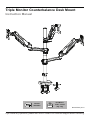
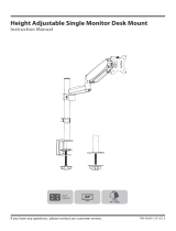
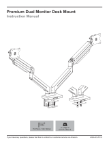
Triple Monitor Counterbalance Desk Mount
Instruction Manual
If you have any questions, please feel free to contact our customer support before returning.
MU-AHP-D63H_US1.0
75×75mm
100×100mm
Each Monitor:
4.4 Ibs ~ 19.8 Ibs
(2kg ~ 9kg)
Load
Capacity

Safety Caution
BEFORE ASSEMBLY
● Layout all components and hardware. Check all parts are included and undamaged.
● Should anybody intends to install or use this mount, please read and understand this manual carefully.
● If you do not understand these instructions or have any doubt about the safety instructions, assembly or use of this
product, please contact our customer service.
WARNING
● This product contains small items that could be a choking hazard if swallowed.
● KEEP AWAY FROM CHILDREN UNDER 3 YEARS OLD. ADULT SUPERVISION IS REQUIRED.
● Improper installation, such as using the product for monitors over its load capacity or for any purpose not explicitly
specified, may cause damage or serious injury. We would not be liable for any damage or injury caused by improper
mounting or inappropriate use.
CAUTION AND MAINTENANCE
● Never allow children to climb, stand, hang, or play on any part of monitor or stand.
● This product is intended for indoor use only. Using this product outdoors could lead to product failure and personal injury.
● Check that the bracket is secure and safe to use at regular intervals (at least every three months).
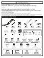
01 NOTE: Not all hardware included will be used.
PACKAGE CONTENTS
3B (x1)
Upper Pole
M-A (×12)
Screw M4×12mm
M-C (×12)
Washer d5mm
M-D (×24)
Spacer H5mm
M-B (×12)
Screw M4×30mm
1A (x3)
Arm
1B (x3)
Cable Cover
3A (x1)
Lower Pole
04 (x1)
Decorative Cover
02 (x3)
VESA Plate
05 (x1)
Support Plate
06 (x1)
L Plate
07 (x1)
Clamp
7-2
Clip Plate
7-5
Washer
7-3
Bolt
7-4
screw
All are included in 07
7-1
Bracket
D3 (×1)
2.5mm Allen Key
D1 (×1)
5mm Allen Key
D2 (×1)
6mm Allen Key
G (×1)
Cable Clip
H (×3)
Fixator
E (×3)
Pad
A (×2)
Bolt M6×8mm
C (×1)
Bolt M8×10mm
B (×2)
Bolt M6×10mm
I (×1)
Set Screw M5×5mm
F (×3)
Security Bolt

02
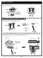
ASSEMBLY STEPS
STEP 1: Apply Pads to the Base Bottom
Apply the pads (E) onto the bottom of lower pole (3A) to avoid desk scratches.
E
3A
OPTION A : Clamp Installation
1. Connect the base of lower pole (3A) and the L plate (06) by using the screws (A).
2. Tighten the screw (B).
3. Connect the clamp (07) and the L plate (06) by using the screws (A).
STEP 2: Clamp Installation or Grommet Base Installation
M6x10mm
D1
A
0.39~1.97"
(10~50mm)
1.97~3.15"
(50~80mm)
B
M8x10mm
A
M6x8mm
07
3A
06

03
OPTION B: Grommet Base Installation
Detach the bolt (7-3) from the clamp (07).
07 7-1
7-2
7-3
7-4
7-5
Use the bolt (7-3) through the hole on support plate (05) to fix the lower pole (3A) and the table
board together. Install the decorative cover (04) to base finally.
0.39~1.97"
(10~50mm)
05
3A
7-3
STEP 2: Continued
Fix the decorative cover (04) to the base of lower pole (3A) and fix the bracket on the table by
tightening the clamp (07).
3A
04
0.39~3.15"
(10~80mm)
07
04

04
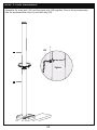
STEP 3: Pole Installation
Assemble the lower pole (3A) and the upper pole (3B) together. Secure the pole assembly
with the preassembled screw (I) and Allen key (D3).
3A
3B D3
I
Tighten

05
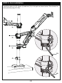
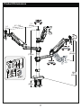
STEP 4: Arm Installation
Install the cable clip (G), fixator (H) and arm (1A) to the pole as shown below. Then fasten the
bolts with Allen key (D1, D2).
1A
H
1A
H
G
1A
H
D2
D1

06
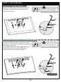
Attach the VESA plate (02) to back of monitor
and secure it with screws and waswhers by
using Allen key (D1).
Please make sure you don’t tighten
the screws much excessively or it
may cause your monitor damage.
OPTION A: Flat Back Monitor
02
Attach the VESA plate (02) to back of monitor
and secure it with screws, waswhers and spacers
byusing Allen key (D1).
Put 4 spacers between VESA plate and monitor.
Install 4 long screws through VESA plate,
spacers to monitor via mounting holes.
Please make sure you don’t tighten
the screws much excessively or it
may cause your monitor damage.
OPTION B: For Recessed / Curved Back Monitor
02
STEP 5: Attach Monitor
D1
D1

07
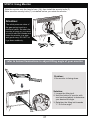
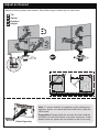
STEP 6: Hang Monitor
Slide the monitor onto the head of arm (1A), then install the security bolts (F).
Make sure the security bolts (F) is installed before you rotate the monitor.
Attention:
The initial pressure value of
the gas spring is set to a
minimum value. So when the
monitor is hung on, you need
to hold it with both hands and
leave the monitor in a slow
and gentle way. DO NOT let
it go down suddenly.
refer to below illuminations to adjust tilting angle of your monitor
Problem:
If the monitor is facing down.
Solution:
1. Loosen the tilting bolt.
2. Hold the bottom of monitor with
one hand and adjust to determine
your desired tilt angle.
3. Retighten the tilting bolt towards
"+" to fix the angle.
F
D2

08
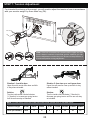
STEP 7: Tension Adjustment
For intended functioning of the mount, you will need to adjust the tension of arm in accordance
with your monitor weight by 6mm Allen key (D2).
Note: For how many circles the screw should be turned, please refer to the table below.
Monitor Weight
Circles (AT LEAST)
6.6 lbs
2min
4.4 lbs
4
8.8 lbs 11 lbs 13.2 lbs 15.4 lbs 17.6 lbs 19.8 lbs
6 8 10 12 15
Situation 1: Arm falls down
Upper Arm with monitor falls down and fails
to stay where intended.
Solution:
Turn the inside screw counterclockwise
(“+”direction) to increase gas spring tension
until the arm can stay as intended.
Situation 2: Arm rises up or can't press down
Upper Arm with monitor rises up and fails to stay
where intended.
Solution:
Turn the inside screw clockwise (“-”direction) to
decrease gas spring tension until the arm can stay
as intended.
Note: If the bolt is covered over, please hold the upper arm and
press it down to maintain a horizontal position, and then you can
see the adjustment screw at the joint. Be sure to keep the arm in
a horizontal position during adjustment.
D2

09
STEP 8: Cable Management
Lower Arm
1.Remove the bottom cable cover by using a Allen key (D1).
2.Run cables through the cable cover.
3.Install and fix the cable cover on the arm by using a Allen key (D1).
Upper Arm
Run cables through the cable cover (1B),
then insert the cable cover into the upper arm.
Run cables through the cable cover.
DD
1B

Adjust as Desired
DESK DESK
Please do not move stand outside desk for safety!
Tilt
Swivel
Rotation
Height
10
Adjust monitor position and rotation. Store Allen keys in cable clip for future use.
Note: To ensure stability, the tightness of the rotating axis
has been preset, so it would be kind of difficult to rotate the
VESA plate.
Suggestion: Please attach the monitor first, then hold the
two sides of it with both hands, and rotate vigorously. If that
doesn't work out, please do not hesitate to ask for our help.
Rotate Vigorously

11
Product Dimensions
7.3"
(185mm)
2.4"
(60mm) 8.5"~10.8"
(215mm~275mm)
±90°
11.4"
(290mm)
MAX:
36.3"
(922mm)
28"
(712mm)
3.7"
(94mm)
-
 1
1
-
 2
2
-
 3
3
-
 4
4
-
 5
5
-
 6
6
-
 7
7
-
 8
8
-
 9
9
-
 10
10
-
 11
11
-
 12
12


MOUNTUP MU6013A User manual
- Category
- Flat panel desk mounts
- Type
- User manual
Ask a question and I''ll find the answer in the document
Finding information in a document is now easier with AI
Related papers


Other documents
-
 Mount-It MOUNT-IT TPM-MA09 Height Adjustable Single Monitor Desk Mount User manual
-
HUANUO Dual Monitor and Laptop Mount User manual
-
-
-
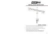 MOUNTPRO Dual Monitor Stand Mount, Height Adjustable LCD Monitor Desk Mount, Articulating Full Motion Tilt Swivel Monitor Arm - Fits 13" to 27" Computer Screens, Each Arm Holds up to 19.8lbs., VESA 75 100 User manual
-
 Mount AG9-42-US1.0 User manual
-
-
-
Vivo STAND-V104A Assembly Instructions
-


