Page is loading ...

HNTS4B
INSTRUCTION
MANUAL
Rev00(A)
(US/CA) 1-800-556-0533
(UK) 44-808-196-3874 [email protected]
www.huanuo.com
WWW.
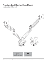
Laptop & Monitor Mount
02 03 04
05 06 07 08
09 10 11 12
13 14 15 16

IMPORTANT SAFETY INFORMATION
Weight Restrictions
Check the VESA Pattern of Your Monitor Before Installation
If your monitor and laptop weigh more than the weight above, the mount
is NOT compatible. Monitor and monitor should not exceed weight
capacity.
WARNING
DO NOT exceed the maximum weight indicated. This mounting
system is intended for use only within the weight range listed.
Exceeding the maximum weight limit may result in failure of
the mount, causing potential damage and/or injury.
It is the responsibility of the installer to verify the total weight
of the monitor and any accessories attached.
• Please carefully read all instructions before attempting installation. If you do not understand the
instructions or have any questions or concerns, please contact our Technical Support at
1-800-556-0533 (US/CA) / 44-808-196-3874 (UK) or Customer Service at
CAUTION: Avoid potential injuries and property damage!
• Do not use this product for any purpose that is not explicitly specified in this manual. Do not
exceed weight capacity. We are not liable for damage or injury caused by improper mounting,
incorrect assembly or inappropriate use.
• This product contains gas spring arms which are under high pressure. Do not puncture these arms
or expose the arms to fire or flame. If product is defective, please contact our Technical Support at
1-800-556-0533 (US/CA) / 44-808-196-3874 (UK) or Customer Service at
• Do not use this product on desks made of particle board or other soft woods.
• The information contained in this manual does not cover all possible conditions or variables in
relation to the installation of this product.
If your monitor's VESA pattern is smaller than 75mm x 75mm / 3″ x 3″ or greater than
100mm x 100mm / 3.9″ x 3.9″, this mount is NOT COMPATIBLE. Please contact our
Technical Support at 1-800-556-0533 (US/CA) / 44-808-196-3874 (UK) or
Customer Service at [email protected] to find a compatible product.
Minimum: 75mm x 75mm / 3″ x 3″ (W x H)
Maximum: 100mm x 100mm / 3.9″ x 3.9″ (W x H)
Measure Your Monitor's VESA Pattern:
MAX: 100mm/3.9″
MAX: 100mm/3.9″
Monitor
8KG
(17.64 lbs)
Laptop
5KG
(11.02 lbs)
02 03 04
05 06 07 08
09 10 11 12
13 14 15 16

360°
• Please carefully read all instructions before attempting installation. If you do not understand the
instructions or have any questions or concerns, please contact our Technical Support at
1-800-556-0533 (US/CA) / 44-808-196-3874 (UK) or Customer Service at
CAUTION: Avoid potential injuries and property damage!
• Do not use this product for any purpose that is not explicitly specified in this manual. Do not
exceed weight capacity. We are not liable for damage or injury caused by improper mounting,
incorrect assembly or inappropriate use.
• This product contains gas spring arms which are under high pressure. Do not puncture these arms
or expose the arms to fire or flame. If product is defective, please contact our Technical Support at
1-800-556-0533 (US/CA) / 44-808-196-3874 (UK) or Customer Service at
• Do not use this product on desks made of particle board or other soft woods.
• The information contained in this manual does not cover all possible conditions or variables in
relation to the installation of this product.
Product Features
Grommet Mounting for grommet bolt
0.39 - 2.16″ (10 - 55mm)
360°
C-Clamp Mounting for table edge
0.39 - 3.15″ (10 - 80mm)
27.56″
(700mm)
+85°/ -90°
360° 360°
180°
02 03 04
05 06 07 08
09 10 11 12
13 14 15 16

DO NOT adjust tension without monitor attached.
1. Verify the weight of your monitor (including accessories) is less than
18 lbs (8 kg).
2. Monitor weight can be found in manual or on manufacturer's website.
3. Ensure monitor has been securely attached to the mount.
TENSION ADJUSTMENT SHOULD ONLY BE
PERFORMED AFTER MONITOR INSTALLATION
Attention
WARNING:
• Gas Spring Arm is under pressure and should be handled with care.
• Failure to follow the instructions may result in damage to the mount and/or
personal injury.
02 03 04
05 06 07 08
09 10 11 12
13 14 15 16

Supplied Parts and Hardware
Supplied Parts and Hardware for Step 1
Tools Needed (Not lncluded)
3/16″ (5mm)
Large Allen Key
O x 1
1/8″ (3mm)
Small Allen Key
I x 1
Base
S x 1
Pole
T x 1 Base Plate
M x 1
5/32″ (4mm)
Medium Allen Key
J x 1
WARNING: This product contains small parts that may pose a choking hazard.
Before starting assembly, verify all parts are included and undamaged. Do not use
damaged or defective parts. lf you require replacement parts, please contact our
Technical Support at 1-800-556-0533 (US/CA) / 44-808-196-3874 (UK) or Customer
Service at [email protected].
• NOTE: Not all hardware included in this package will be used.
Tape Measure Drill (Optional) 7/16-7/8″ (11-22mm)
Drill Bit(Optional)
Supplied Parts and Hardware for Step 2
Arm Support
X x 1
Non-slip Pad
N x 2
Locating Ring
K x 1
VESA Plate
V x 1
Laptop Mount
f x 1
Extension Arm
Y x 3
Compression Arm
W x 2
Cable Management Cover
P x 2
Decorative Cover
H x 5
Bolt
M5 x 6 mm
E x 6
Set Screw (Spare)
M6 x 6 mm
x 2
NOTE: The set screws [N] are
spare screws which can be
used if the preassembled set
screws on the arms [Y] and
compression arms [W] are
missing.
Bolt
M5 x 12mm
F x 4
Nut
M5
G x 4
02 03 04
05 06 07 08
09 10 11 12
13 14 15 16

Monitor Plate
U x 2
Bolt
M4 x 12mm
A x 9
Bolt
M4 x 30mm
B x 9
Washer
10 x 4.3 x 1mm
C x 8
Spacer
10 x 5.2 x 13mm
D x 8
Hardware for Step 4 Hardware for Step 5
Supplied Parts and Hardware for Step 3
Cable Clip
L x 2
T
S
I
1/8″ (3mm)
Option A: For Clamp Mounting
Step 1 Install the Base
Measure the thickness of the desk.
If the desk thickness is 0.98 - 3.15″ (25 - 80mm), skip this step and go to STEP A-1 and A-2.
If the desk thickness is 0.39 - 2.56″ (10 - 65mm), reinstall the C-Clamp as shown below.
O
3/16″ (5mm)
A-1 Thread the pole [T] into the base [S]. A-2 Tighten the knob against the desk to
mount the C-Clamp.
O
3/16″ (5mm)
Bolt
M6 x 8mm
Q x 2
02 03 04
05 06 07 08
09 10 11 12
13 14 15 16

Option B: For Grommet Mounting
B-1 Detach the base [S] entirely. Keep the C-Clamp brace [a], locking plate [b] and grommet
bolt [c] for the use of PAGE 08.
c
b
a
O
3/16″ (5mm)
B-2 Attach the base plate [M] to the bottom of the base.
dJ
5/32″ (4mm)
M d
J
5/32″ (4mm)
J
5/32" (4mm)
02 03 04
05 06 07 08
09 10 11 12
13 14 15 16

3
B-4 Secure the pole assembly to the desktop by screwing grommet bolt [c] through the
desk and locking plate [b] and into the base.
c
b
7/16-7/8″
(11-22mm)
0.39-2.36″
(10-60mm)
2″ (50mm)
Drill
(Not Included)
7/16-7/8″
(11-22mm)
Drill Bit
(Not Included)
NOTE: If a hole is needed for grommet
installation, be sure to leave at least 2″
(50mm) from the edge of desktop and
mark where the hole will be drilled. Use
either a 7/16-7/8″ (11-22mm) drill bit
for this step.
B-3 Thread the pole [T] into the base.
TI
1/8″ (3mm)
φ10-φ50mm
02 03 04
05 06 07 08
09 10 11 12
13 14 15 16

Step 2 Secure the Arm Assembly to the Pole Assembly
2-2 Slide the two extension arms [Y] onto the arm support [X], then tighten the set
screws.
2-1 Slightly loosen the set screws of locating ring [T] and arm support [X]. Slide them
and extension arm [Y] in sequence onto the pole at your desired height as shown.
Tighten the set screws to secure them.
O
3/16″ (5mm)
I
1/8″ (3mm)
X
KK
Y
KK
H
H
Y
Y
02 03 04
05 06 07 08
09 10 11 12
13 14 15 16

I
1/8″ (3mm)
2-3 Attach the cable management
covers [P] to the compression arms [W].
2-4 Slide the two compression arms [W] onto the two extension arms [Y], then tighten
the set screws.
E
E
E
WP
H
W
H
W
J
5/32" (4mm)
Assembled cable
management
cover face down.
02 03 04
05 06 07 08
09 10 11 12
13 14 15 16

Step 3 Attach the Monitor Plates to the Monitors
2-5 Connect the VESA plate [V] with the laptop mount [f].
N
J
5/32″ (4mm)
F
F
F
G
G
G
G
F
f
V
N
3-1 Select Monitor Bolts
3-2 Attach the Monitor Plates to Your Monitors
Hand thread bolts into the threaded inserts on the back of your monitor to determine which bolt (M4
x 12mm or M4 x 30mm ) to use. A minimum of 4-5 turns into the threading is required. Do not turn
past the bottom of the hole.
M4 x 12mm
M4 x 30mm
D
O
N
O
T
o
v
e
r
t
i
g
h
t
e
n
Option A:For Flat Back Monitor
A
C
The hanging tab is
directed toward the
top of monitor.
J
5/32″ (4mm)
U
N
02 03 04
05 06 07 08
09 10 11 12
13 14 15 16

HEAVY! You may need
assistance with this step.
QQ
J
5/32″ (4mm)
D
O
N
O
T
o
v
e
r
t
i
g
h
t
e
n
Option B:For Curved Monitor
B
C
D
The hanging tab is
directed toward the
top of monitor.
J
5/32″ (4mm)
U
Step 4 Attach the Monitors and Laptop Mount
02 03 04
05 06 07 08
09 10 11 12
13 14 15 16

Step 5 Rotation Restriction
H
f
Incorrect orientation Correct orientation
To ensure proper stability, do not position monitors behind base. Monitors and arms should remain
over the desktop. Failure to do so may cause instability, resulting in property damage or injury.
I
1/8″ (3mm)
02 03 04
05 06 07 08
09 10 11 12
13 14 15 16

6-1 Carefully press down on the compression arm so that it is level with the desk (This
may require more force than you think. Ask for help if needed). you can access the
adjustment screw increase or decrease the tension to balance the arm.
6-2 To properly balance the arm with monitor mounted, adjust the spring tension using
the supplied Allen Key as follows:
If the arm drops, turn the adjustment screw
counter-clockwise until it stays in a
horizontal position.
If the arm rises, turn the adjustment screw
clockwise until it stays in a horizontal position.
6-1
6-2
O
3/16″ (5mm)
Step 6 Secure the Arm Assembly to the Pole Assembly
CAUTION:
To avoid damage to monitor or
mount, always keep the arm in a
horizontal position while making
adjustments. Again, ask for
assistance if needed.
02 03 04
05 06 07 08
09 10 11 12
13 14 15 16

Step 7 Tilt and Swivel Adjustment
Step 8 Rotation Adjustment
WARNING:
Do not overtighten or
overloosen the bolts.
WARNING:
Ensure bolts are
secured firmly before
rotation.
Directly adjust your monitor by gripping the
laptop mount edges / monitor edges (do
not press on the screen itself).
If it is difficult to adjust, slightly loosen the
bolt. Move the laptop mount / monitor to
your desired position, and retighten the
bolt to hold it in the desired position.
Swivel Adjustment Tilt Adjustment
TightenTighten
Loosen
Loosen
TightenTighten
Loosen
Loosen
O
3/16″ (5mm)
O
3/16″ (5mm)
360° Rotation360° Rotation
Firmly hold monitor at edges
and rotate from Landscape
to Portrait mode.
02 03 04
05 06 07 08
09 10 11 12
13 14 15 16

Step 9 Route Cables Along the Arm
Route the cables using the cable management covers [P] on the compression arms and
the preassembled covers on the extension arms [Y].
Attach the cable
clips [L] to the pole.
L
L
YW
P
Store the Allen keys in
the cable clip.
O
3/16″ (5mm)
I
1/8″ (3mm)
J
5/32″ (4mm)
860-00514-00 Rev00
02 03 04
05 06 07 08
09 10 11 12
13 14 15 16
/