Page is loading ...

VIPER SC+
™
BASE STATION
DIGITAL INFRASTRUCTURE FOR VIPER SC+ SERIES
User Manual
Viper SC+™ Base Station Digital Infrastructure for Viper SC+ Series
PN 001-5100-000 Rev. B
Revised February 2014

REVISION HISTORY
REV
DATE
REVISION DETAILS
0
December 9, 2009
Initial release 001-5100-000.
1
June 15, 2010
Section added regarding RADIUS Server: Section 6.5.3..
2
August 3, 2010
Section added regarding Multi-speed: Section 6.9.
Added information about Boot Delay parameter: Section 6.13.1.
Updated available part numbers to include Viper SC version sections 1.3.1.
3
March 7, 2011
Added Section regarding SNMP: Section 6.8 (renumbered following sections)
Added information about Warm Standby: Sections 4.2.2, 4.4.3, and 6.14
Removed references to Repeater Base Stations
Updated several webpage screen shots: Figure 6.1, 6.2, 6.15
4
August 3, 2011
Added Declaration of Conformance and Regulatory Certifications (Appendix B)
Added ETSI Base Station Part Numbers (Section 1.3)
Updated VHF ETSI frequencies from 136-174 to 142-174MHz.
Updated RF Exposure Compliance Requirements since Viper User Manual was
reorganized and section 2.6.6 has been moved.
Added relevant regulatory standards in Appendix B.
5
August 24, 2011
Added Section for the QoS and QoS Statistics pages.
Updated figure 20 and 21.
Updated EU and EFTA Member States’ Acceptable Frequency Table in Appendix B.
6
November 18, 2012
Reorganized some content to be more user-friendly. Added additional references to
figures and tables. Renumbered some sections. Replaced RF Exposure Compliance
Requirements to match what is in the Viper SC Router Manual. Added a header. Fixed
footers so they are book style layout. Improved layout of the Table of Contents. Added a
Table of Figures. Deleted any duplicate information in the manual. Added a Customer
Service Section.
A
January 2014
Added new models, Viper SC™+; all Viper SC™ models become Viper SC+ when upgraded
with new Viper SC+ firmware. Updated the chapter about the Viper Web Interface to
add sections to explain the new menu selections for DeviceOutlook™ and IP Relay Agent.
B
February 2014
Corrected Section 6 – Firmware Upgrade instructions were in error.

Viper SC +™ Base Station Digital Infrastructure for Viper SC+ Series PN 001-5100-000 Rev. B | Page i
Important Notice
Because of the nature of wireless communication, transmission and reception of data can never be
guaranteed, Data may be delayed, corrupted (i.e. have errors), or be totally lost. Significant delays or losses
of data are rare when wireless devices such as the Viper SC+™ and Viper SC+ Base Station are used in a
normal manner with a well-constructed network. Viper SC+ Base Station should not be used in situations
where failure to transmit or receive data could result in damage of any kind to the user or any other party,
including but not limited to personal injury or death, or loss of property. CalAmp accepts no responsibility
for damages of any kind resulting from delays or errors in data transmitted or received using Viper SC+ or
Viper SC+ Base Station, or for the failure of Viper SC+ or Base Station to transmit or receive such data.
Copyright Notice
© 2009-2013 CalAmp. All rights reserved.
Products offered may contain software which is proprietary to CalAmp. The offer or supply of these
products and services does not include or infer any transfer of ownership. No part of this documentation or
information supplied may be divulged to any third party without the express written consent of CalAmp.
CalAmp reserves the right to update its products, software, or documentation without obligation to notify
any individual or entity. Product updates may result in differences between the information provided in this
manual and the product shipped. For access to the most current product documentation and application
notes, visit www.calamp.com.
RF Exposure Compliance Requirements
Viper SC+ radios are intended for use in the Industrial Monitoring and Control and SCADA
markets. Each Viper SC+ unit must be professionally installed and must ensure a minimum
separation distance listed in the table below between the radiating structure and any person.
An antenna mounted on a pole or tower is the typical installation and in rare instances, a 1/2-
wave whip antenna is used.
Minimum Safety Distance
Antenna Gain
(cm @max power)
5 dBi
10 dBi
15 dBi
132 MHz (VHF)
123 cm
219 cm
389 cm
215 MHz (UHF)
123 cm
219 cm
389 cm
406.1 MHz
106 cm
188 cm
334 cm
900 MHz (Model/PN 140-5198-304, 140-5398-304)
66 cm
117 cm
208 cm
900 MHz (Model/PN 140-5198-504, 140-5398-504)
64 cm
115 cm
202 cm
Note: It is the responsibility of the user to guarantee compliance with the FCC MPE regulations when
operating this device in a way other than described above. The installer of this equipment must ensure the
antenna is located or pointed such that it does not emit an RF field in excess of Health Canada limits for the
general population.
Viper SC+ uses a low-power radio-frequency transmitter. The concentrated energy from an antenna may
pose a health hazard. People should not be in front of the antenna when the transmitter is operating.
The installer of this equipment must ensure the antenna is located or pointed such that it does not emit an
RF field in excess of Health Canada limits for the general population. Recommended safety guidelines for the
human exposure to radio-frequency electromagnetic energy are contained in the Canadian Safety Code 6
(available from Health Canada), the Federal Communications Commission (FCC) Bulletin 65, and the Council
of the European Union’s Recommendation of 12 July 1999 on the limitation of exposure of the general
public to electromagnetic fields (0 Hz to 300 GHz) (1999/519/EC)

Viper SC +™ Base Station Digital Infrastructure for Viper SC+ Series PN 001-5100-000 Rev. B | Page ii
Caution: Before you deploy your system, you must read and understand Section 2.2 Selecting Antenna and
Lightning Arrestor Combinations.
Exigences de conformité d'exposition aux Radiofréquences
La radio Viper SC+ est destinée à être utilisé dans les marchés contrôles industriels et
SCADA. L'unité Viper SC doit être installée par un professionnel et doit assurer une distance
minimale de séparation entre les sources radiantes et toute personne. Les distances sont
indiquées dans le tableau ci-dessous. L’installation typique est une antenne de type fouet
1/2-longueur d’onde installée sur un poteau ou pylône.
Distance de sécurité minimum
Gain de Antenne
(puissance cm @ max)
5 dBi
10 dBi
15 dBi
132 MHz (VHF)
123 cm
219 cm
389 cm
215 MHz (UHF)
123 cm
219 cm
389 cm
406.1 MHz
106 cm
188 cm
334 cm
900 MHz (Modèle # 140-5198-304, 140-5398-304)
66 cm
117 cm
208 cm
900 MHz (Modèle # 140-5198-504, 140-5398-504)
64 cm
115 cm
202 cm
Note: Il est de la responsabilité de l'utilisateur de garantir le respect des règlements MPE de la FCC lorsque
vous utilisez cet appareil d'une façon autre que celle décrite ci-dessus. L’installateur doit s'assurer que
l'antenne est située ou orientée de façon à ne pas émettre un champ RF dépassant les limites de radiations
pour la population générale établies par Santé Canada.
La radio Viper SC+ utilise un émetteur à radiofréquence à faible puissance. L’énergie concentrée d'une
antenne peut poser un risque pour la santé. On ne devrait pas être en face de l'antenne lorsque l'émetteur
est en marche.
Les consignes de sécurité recommandées pour l'exposition humaine à l'énergie électromagnétiques de
radiofréquences sont contenues dans le Code 6 canadien de la sécurité (disponible auprès de Santé Canada),
la Commission Communications Fédéral (FCC) Bulletin 65 et la recommandation du 12 Juillet 1999 sur la
limitation de l'exposition du public aux champs électromagnétiques (de 0 Hz à 300 GHz) (1999/519/CE) du
Conseil de l'Union européenne.
Class A Digital Device Compliance
Note: This equipment has been tested and found to comply with the limits for a Class A digital device,
pursuant to part 15 of the FCC Rules. These limits are designed to provide reasonable protection against
harmful interference when the equipment is operated in a commercial environment. This equipment
generates, uses, and can radiate radio-frequency energy and, if not installed and used in accordance with
the instruction manual, may cause harmful interference to radio communications. Operation of this
equipment in a residential area is likely to cause harmful interference in which case the user will be required
to correct the interference at his or her own expense.
Any changes or modifications not expressly approved by the party responsible for compliance (in the
country where used) could void the user’s authority to operate the equipment.

Viper SC+™ Base Station Digital Infrastructure for Viper SC+ Series PN 001-5100-000 Rev. A | Page iii
TABLE OF CONTENTS
1 Viper SC+ Base Station Overview .................................................................................................... 1
1.1 Viper SC+ Standard Base Station Overview ........................................................................................................... 2
1.2 Viper SC+ Redundant Base Station Overview ........................................................................................................ 3
1.3 Base Station Control Panels & Connections ........................................................................................................... 4
1.3.1 Control Panel Features ................................................................................................................................. 4
1.3.2 Base Station Connections ............................................................................................................................. 6
1.4 Part Numbers ....................................................................................................................................................... 11
1.4.1 Viper SC+ Base Station Part Numbers ......................................................................................................... 11
1.4.2 Base Station Internal IP Radios ................................................................................................................... 12
1.4.3 Antenna Feedline ........................................................................................................................................ 13
1.5 Components ......................................................................................................................................................... 14
1.5.1 Basic Unit .................................................................................................................................................... 14
2 Antennas and RF Exposure ........................................................................................................... 15
2.1 Selecting Antenna and Feedline ........................................................................................................................... 15
2.1.1 Antenna Gain .............................................................................................................................................. 15
2.1.2 Types of Antennas ...................................................................................................................................... 16
2.1.3 Feedline ...................................................................................................................................................... 16
2.2 Selecting Antenna and Lightning Arrestor Combinations .................................................................................... 17
2.2.1 Lightning Arrestor Overview ....................................................................................................................... 17
2.2.2 Antenna Overview ...................................................................................................................................... 17
2.2.3 The Wrong Combination ............................................................................................................................. 18
2.2.4 Good Design Practices ................................................................................................................................ 19
2.2.5 RF Exposure Compliance Requirements ..................................................................................................... 20
3 Getting Started: Quick Setup and Initial Configuration ................................................................ 22
3.1 Measure Primary Power ...................................................................................................................................... 22
3.2 Connect the Viper SC+ to Programming PC ......................................................................................................... 22
3.3 LAN Configuration ................................................................................................................................................ 23
3.4 Log In .................................................................................................................................................................... 26
3.5 Introduction to the Viper SC+ Base Station Web Interface .................................................................................. 27
3.6 Initial Configuration Using the Setup Wizard ....................................................................................................... 28
3.6.1 Setup Wizard 1: Ethernet IP Address and Login Security ........................................................................... 29
3.6.2 Setup Wizard 2: LAN Configuration ............................................................................................................ 32
3.6.3 Setup Wizard 3: Ping Settings ..................................................................................................................... 33
3.6.4 Setup Wizard 4: Static Routes and Routing Table ....................................................................................... 34
3.6.5 Setup Wizard Complete .............................................................................................................................. 35
4 Base Station Operation ................................................................................................................. 36

Viper SC +™ Base Station Digital Infrastructure for Viper SC+ Series PN 001-5100-000 Rev. B | Page iv
4.1 Viper SC+ Failure Detection ................................................................................................................................. 36
4.2 Monitor Viper SC+ With Ethernet Connection ..................................................................................................... 36
4.3 Monitor Transmit Power ...................................................................................................................................... 37
4.4 Monitor Receive and Transmit Data / Send Pings ............................................................................................... 37
4.5 When a Failure is Detected .................................................................................................................................. 37
5 Viper SC+ Base Station Web Interface .......................................................................................... 39
5.1 Status (Home Page) .............................................................................................................................................. 40
5.2 Setup Wizard ........................................................................................................................................................ 42
5.3 Controller Settings ............................................................................................................................................... 42
5.3.1 Setup (Basic) ............................................................................................................................................... 42
5.3.2 Diagnostics (Controller Board) .................................................................................................................... 46
5.3.3 Routing Table .............................................................................................................................................. 47
5.3.4 SNMP .......................................................................................................................................................... 49
5.3.5 QoS .............................................................................................................................................................. 51
5.3.6 QoS Statistics .............................................................................................................................................. 56
5.3.7 Alarm Port ................................................................................................................................................... 57
5.3.8 IP Relay Agent ............................................................................................................................................. 61
5.3.9 Multi-Speed ................................................................................................................................................ 62
5.3.10 Firmware Update ........................................................................................................................................ 66
Radio Settings ................................................................................................................................................................. 67
5.3.11 Setup (Basic) ............................................................................................................................................... 67
5.3.12 Setup Basic .................................................................................................................................................. 67
5.3.13 Diagnostics .................................................................................................................................................. 68
5.4 System Monitor .................................................................................................................................................... 69
5.4.1 Redundant Setup ........................................................................................................................................ 69
5.4.2 Ping Statistics .............................................................................................................................................. 71
5.5 Reset Unit ............................................................................................................................................................. 72
6 Upgrading Firmware ..................................................................................................................... 73
6.1 Firmware update .................................................................................................................................................. 73
6.2 Upload Firmware ................................................................................................................................................. 73
6.2.1 current Firmware version ........................................................................................................................... 73
6.2.2 Upload new Firmware ................................................................................................................................ 74
6.2.3 Upload new Firmware ................................................................................................................................ 74
APPENDIX A — Abbreviations and Definitions ............................................................................. 75
APPENDIX B —Viper SC+ Base Station Specifications ...................................................................... 78
General Specifications .................................................................................................................................................... 78
Overall Dimensions and Mounting Hole Locations ......................................................................................................... 85
APPENDIX C — Regulatory Certifications ......................................................................................... 86

Viper SC +™ Base Station Digital Infrastructure for Viper SC+ Series PN 001-5100-000 Rev. B | Page v
DECLARATION OF CONFORMITY FOR MODELS # 140-5018-60x, 140-5048-40x, and 140-5048-60x ....................... 88
EU and EFTA Member States’ Acceptable Frequency Table ..................................................................................... 89
FCC Emission Designators .......................................................................................................................................... 90
FCC Emission Designators .......................................................................................................................................... 91
FCC Emission Designators .......................................................................................................................................... 92
FCC Emission Designators .......................................................................................................................................... 93
APPENDIX D — Service And Support And Warranty Statement ................................................... 94
Warranty Statement ....................................................................................................................................................... 95

Viper SC+™ Base Station Digital Infrastructure for Viper SC+ Series PN 001-5100-000 Rev. B | Page 1
1 VIPER SC+ BASE STATION OVERVIEW
The Viper SC+ Base Station is available in two options: Standard and Redundant.
The Standard Base Station uses a single Viper SC+ radio to transmit and receive data from remote radios.
The Redundant Base Station uses two Viper SC+ radios, activating only one at a time, in order to provide a fail-safe
in the event of a radio failure.
The Viper SC+ Base Station has a main controller PC board which is accessible via HTML web pages. You must access
the controller’s web pages to configure the user-programmable settings and to view the status of the Base Station.
Rugged Packaging. The Viper SC+ Base Station is housed in a rugged, 19-inch-rack-mountable aluminum case. Built for
industrial applications in a variety of environments, the Viper SC+ Base Station operates over an extended temperature
range and provides worry-free operation in the roughest environments.
Simple Installation. Basic installation typically utilizes an omnidirectional antenna at the Viper SC+ Base Station or
Relay Point, and a directional antenna at each remote site that is not a Relay Point. See Chapter 2 about Antennas and
RF Exposure for information about antennas. For basic service, just hook up an antenna, connect your Ethernet LAN to
the Base Station’s LAN port, apply primary power, then check and set operating parameters.
Flexible Management. Configuration, commissioning, maintenance, and troubleshooting can be done locally or
remotely. All operating parameters can be set via a Web browser. See Chapter 5, which documents the Viper SC+ Base
Station Web Interface.
The Viper SC+ Base Station consists of a Controller Board, and LED display board, two fans, and shelving to house one
(Standard) or a pair of (Redundant) Viper SC+ radios in a rugged aluminum case. The unit is not hermetically sealed and
should be mounted in a suitable enclosure when dust, moisture, or a corrosive atmosphere are anticipated.
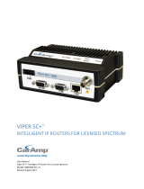
The Viper SC+ Base Station is designed for easy installation and configuration. The Viper SC+ Base Station features two
external buttons. However, all operating parameters may be set by connecting to the Viper SC+ Base Station via
Ethernet and using a web browser. The following figure shows the physical dimensions of the Viper SC+ Base Station.
Figure 1 Base Station Dimensions (Units are in inches.)

Viper SC+™ Base Station Digital Infrastructure for Viper SC+ Series PN 001-5100-000 Rev. B | Page 2
1.1 VIPER SC+ STANDARD BASE STATION OVERVIEW
The Standard Base Station consists of one Viper SC+ in a 19-inch-rack-mount enclosure. The Standard Base Station
features two 10/100 BaseT Auto-MDIX Ethernet connections and an I/O Port which can be controlled or monitored
from the Viper SC+ Base Station Controller’s web pages. Both external Ethernet connections are connected by an
embedded Ethernet switch to the radio. The Standard Base Station provides access to the SETUP and COM Ports of the
internal Viper SC+.
As can all Viper SC+ radios, the Viper SC+ in the Standard Base Station can be configured as a relay point if desired.
The following figure shows a simplified block diagram of a Viper SC+ Standard base Station. The Viper SC+ Standard
Base Station consists of a Base Station Controller Board and one Viper SC+ contained in a 3U 19-inch rack-mountable
chassis.
Figure 2 Viper SC+ Standard Base Station Block Diagram
Viper
Base Station
Controller
Board
Front Panel LEDs
Front Panel Switches
1) Radio On/Off
2) Alarm Enable, Disable
Power
(11-30VDC)
Ethernet 1
Ethernet 2
Setup
Com
Ethernet
Setup
Com
Power
Ethernet
Setup
Com
Power
Antenna
To Antenna
LED
Connector
19" Rack Mount Standard Base Station
User Connections
Embedded
Ethernet
Switch
Buzzer
Micro-
processor
Alarm Port

Viper SC+™ Base Station Digital Infrastructure for Viper SC+ Series PN 001-5100-000 Rev. B | Page 3
1.2 VIPER SC+ REDUNDANT BASE STATION OVERVIEW
The Viper SC+ Redundant Base Station has two Viper SC+ radios with identical RF and Ethernet MAC addresses, a
Controller Board, an RF power sensor, and an RF antenna relay inside the 19-inch rack-mountable chassis.
The Viper SC+ Redundant Base Station features two 10/ 100 Base T Auto-MDIX Ethernet connections and an I/O Port
which can be controlled or monitored from the Viper SC+ Base Station Controller’s web pages. Both external Ethernet
connections are connected by an embedded Ethernet switch to the radios. The Viper SC+ Redundant Base Station
provides connections to the SETUP Port and the COM Port of the active Viper SC+ radio. The Ethernet, SETUP, and COM
Ports are automatically routed by the Controller Board to whichever Viper SC+ radio is currently in use.
The following figure shows a simplified block diagram of a Redundant Base Station. The Viper SC+ Redundant Base
Station consists of a Base Station Controller Board, Two Viper SC+ radios, an antenna relay, and an RF power sensor, all
contained in a 3U 19-inch rack-mountable chassis. Only one Viper SC+ operates at a time. When an error is detected
with the primary radio, the Viper SC+ Base Station Controller automatically switches to the backup radio.
Figure 3 Viper SC+ Redundant Base Station Block Diagram
Relay COntrol
Viper A
Base Station
Controller
Board
Antenna
Relay
Power
(11-30VDC)
Ethernet 1
Ethernet 2
Setup
Com
Ethernet A
Ethernet B
Setup A
Setup B
Com A
Com B
Power A
Power B
Ethernet
Setup
Com
Power
Antenna
Viper B
Ethernet
Setup
Com
Power
Antenna
To
Antenna
Power
Sensor
Power
Detector
LED
Connector
19'"Rack Mount Redundant Base Station
User Connections
Embedded
Ethernet
Switch
Ant Relay
Front Panel LEDs
Front Panel Switches
1) Radio Select
2) Alarm Enable, Disable
Buzzer
Micro-
processor
Relay Control
Alarm Port
Radio
Analog IO
Analog IO
A
Analog IO
B
Fwd & Rev Power

Viper SC+™ Base Station Digital Infrastructure for Viper SC+ Series PN 001-5100-000 Rev. B | Page 4
1.3 BASE STATION CONTROL PANELS & CONNECTIONS
1.3.1 CONTROL PANEL FEATURES
The Base Station can come with either of the following front panels.
The panel in the first figure below is used on the Standard Base Station.
The panel in the second figure below is used on the Redundant Base Station.
Each of the front panels has two push buttons and up to seventeen (17) tri-colored LEDs. The functionality of each LED
is described in the table that follows.
Figure 4 Standard Base Station Control Panel
Figure 5 Redundant Base Station Control Panel
Note: It is very common for the base station to indicate errors until it has been configured properly.

Viper SC+™ Base Station Digital Infrastructure for Viper SC+ Series PN 001-5100-000 Rev. B | Page 5
Table 1 Base Station Button Functionality
Base Station Version
Button Name
Button Function
Standard Base Station
Radio On/Off
Toggles the power to the radio on and off.
Alarm On/Off
If an error with the radio is detected, a buzzer in the Viper SC+ Base
Station Controller will sound. This button disables or enables the
alarm buzzer.
Hold the button down for five (5) seconds to clear any radio errors.
You will hear two long beeps as errors are cleared.
Redundant Base Station
Radio Select
Cycles through the modes listed below to turn the power on and off
to the radios and and to select Auto or Manual Mode.
1. Radio A in Use, Auto Mode.
2. Radio A in Use, Manual Mode.
3. Radio B in Use, Auto Mode.
4. Radio B in Use, Manual Mode.
Alarm On/Off
If an error with the radio is detected, a buzzer on the Viper SC+ Base
Station Controller will sound. This button disables or enables the
alarm buzzer.
Note: Hold button down for five (5) seconds to clear any radio
errors. You will hear two (2) long beeps as errors are cleared.
The LED panel has twelve (12 – Standard Base Station) or seventeen (17 – Redundant Base Station) tri-color LEDs. The
functionality of each LED is described in the following table.
Table 2 Base Station LED Functionality
LED
Color
Definition
Power
Green (Solid)
Off
Base Station ready, normal operations
Base Station hardware fault or power is not applied
Status
Green
Red
Base Station has no faults, normal operations
Base Station has a fault condition; check unit status
Fan Error
Red
Off
Indicates a problem with the fans
Fans are operational or power is not applied
COM/SETUP Data
Blinking Red
Blinking Green
Data is transmitting on one of the ports
Data is being received on one of the ports
LINK/ACT 1/2
Solid Red
Flashing Red
Solid Green
Flashing Green
Link at 10 Mbit/s
Activity at 10 Mbit/s
Link at 100 Mbit/s
Activity at 100 Mbit/s
Radio A/B Tx
Red
Radio is transmitting data
Radio A/B In Use
Green
Radio is in use
Radio A/B Error
Off
Red
Flashing Red
No errors have been detected with the radio(s)
An error has been detected with the radio(s)
The maximum number of failures has been reached. For Redundant
Base Station, the Controller will no longer attempt to switch radios.

Viper SC+™ Base Station Digital Infrastructure for Viper SC+ Series PN 001-5100-000 Rev. B | Page 6
LED
Color
Definition
Radio A/B Link/Act
Solid Red
Flashing Red
Solid Green
Flashing Green
Link at 10 Mbit/s
Activity at 10 Mbit/s
Link at 100 Mbit/s
Activity at 100 Mbit/s
Manual Override
(redundant version
only)
Red
Off
Radio selection is done manually
Radio selection is done automatically by the Viper SC+ Base Station
Controller
Alarm Disabled
Red
Off
The onboard buzzer alarm is currently disabled
The buzzer is enabled
1.3.2 BASE STATION CONNECTIONS
Figure 6 Base Station Connections
1.3.2.1 ETHERNET LAN PORTS
The Viper SC+ Base Station has two external Ethernet LAN Ports (see the preceding figure).
The two external Ethernet Ports are connected to each other and to the Viper SC+ radio(s)
inside the Base Station by an embedded Ethernet Switch. Either Ethernet Port can be used. It
is recommended that only one port be connected to the network The unused port can be
used for maintenance or troubleshooting.
The Ethernet LAN ports consist of RJ-45 receptacles with a 10 Base T (or 100 Base T/Tx for 220 MHz and 290 MHz
models) Ethernet connection and Auto-MDIX. Refer to the following table for pin-out descriptions and to instructions
for Initial Configuration Using the Setup Wizard or to instructions for Setup (Basic), to configure the LAN settings for
this port.

Viper SC+™ Base Station Digital Infrastructure for Viper SC+ Series PN 001-5100-000 Rev. B | Page 7
Table 3 – Pin-out for IEEE-802.3 RJ-45 Receptacle Contacts
Contact
10BaseT Signal
1
TXP
(1)
2
TXN
(1)
3
RXP
(1)
4
SPARE
5
SPARE
6
RXN
(1)
7
SPARE
8
SPARE
SHELL
Shield
(1)
The name shows the default function. Given the Auto-MDIX capability
of the Ethernet transceiver, Tx and Rx functions could be swapped.
1.3.2.2 SETUP AND COM PORTS
The SETUP and COM serial connections are DE-9F RS-232 ports. Refer to the
following table for pin-out descriptions for control line configurations of DCD,
DTR, RTS, and CTS control lines.
Serial port considerations:
Base Station SETUP and COM ports are Data Communication Equipment (DCE) devices.
In general, equipment connected to the Base Station’s Setup or COM serial ports are Data Terminal Equipment
(DTE) and a straight-through cable is recommended.
Note: If a DCE device is connected to the Viper serial ports, a null-modem cable or adapter is required.
In a Standard Base Station (with one Viper SC+ radio), the external serial ports are always connected to the Setup
and COM ports of the radio inside the Base Station.
In a two-radio Redundant-Base Station, the two serial ports are connected to whichever radio is currently in use.
When the active radio changes, an internal multiplexer will switch both serial port connections to the second radio.
Table 4 – Pin-Out for DCE SETUP and COM Port, 9 Contact DE-9 Connector
SETUP / COM port Pin-Out
Contact Numbering
Contact
Signal Name
Signal Direction
1
Data Carrier Detect (DCD)
(1)
DTE ← DCE
2
Receive Data (RxD)
DTE ← DCE
3
Transmit Data (TxD)
DTE → DCE
4
Data Terminal Ready (DTR)
DTE → DCE
5
Signal Ground (GND)
DTE ― DCE
6
Data Set Ready (DSR)
(2)
DTE ← DCE
7
Ready To Send (RTS)
(1)
DTE → DCE
8
Clear To Send (CTS)
(1)
DTE ← DCE
9
Ring Indicator (RI)
(3)
DTE ― DCE
(1)
Programmable
(2)
Always asserted
(3)
Future use

Viper SC+™ Base Station Digital Infrastructure for Viper SC+ Series PN 001-5100-000 Rev. B | Page 8
1.3.2.3 ALARM PORT
The Viper SC+ Base Station is equipped with an 8-pin plug that mates to the 8-pin header on the Alarm Port. The Alarm
Port , shown in the following figure, has two relays and a general-purpose input/output pin. In the Redundant Base
Station, one relay can be configured to indicate if an error has been detected with either radio, and the other relay can
be configured to indicate which radio is currently being used.
Alarm Connections
The plug features a spring-loaded retention clamp to make inserting and removing the wire or cable as simple as
possible. To connect wires to the plug, use the following steps.
Step 1. Release Spring Clamp. Insert a small tool into one of the square holes as shown in the following figure. This will
release the spring clamp for the nearest wire to allow the wire to be inserted or removed.
Step 2. Remove Insulation. Strip the insulation off the end of the wire and insert it into the round hole as shown in the
following figure.
Step 3. Remove Tool. Remove the tool. The spring-loaded clamp will hold the wire firmly in place.
Figure 7 Inserting wire into the Alarm Port Plug
Note: Use a small flat-blade screw driver or similar tool specifically for this purpose. Do not use a twisting motion.
1.3.2.4 RADIO I/O PORT
The Radio I/O port is an 8-pin header that provides access to the Base Station radio’s digital or analog I/O lines. These 8
lines are routed to whichever radio is currently in use (Radio A or Radio B in the Redundant Base Station). This port may
be used by future versions of the base station that incorporate radios with input/output lines.
Note: This port is not used and is not connected internally in any version of the Viper SC+ Base Station.

Viper SC+™ Base Station Digital Infrastructure for Viper SC+ Series PN 001-5100-000 Rev. B | Page 9
1.3.2.5 POWER CONNECTOR
The Viper is supplied with a right-angle power connector (10-30 V DC) and 60 inches of cable. The following table
shows the pin-out of the power connector.
When installing the power cable, trim the cable as short as possible to reduce the voltage drop through the wire.
The power connector has four pins. Only pins 2 and 3 need to be connected for normal operation (Main Power and
Ground). Pins 1 and 4 are auxiliary power connections and do not normally need to be connected. These pins are wired
directly to an internal power connector and provide an easy way to power a user’s custom PC board, RTU, or other
equipment that may be mounted inside the Base Station.
Figure 8 Base Station Power Connector and Reset Button location
Table 5 – Pin-Out of the Power Connecto
Power Connector Pin-Out
Contact number
(Left to Right)
Color
Description
4
Not Connected
Auxiliary Power A
3
Black
Ground
2
Red
Positive (10-30) VDC
1
Not Connected
Auxiliary Power B
1.3.2.6 RESET BUTTON
A small hole directly above the Base Station power connector allows access to the reset button. (See the figure above.)
To reset the Viper SC+ Base Station, place the end of a paperclip or similar object into the hole to press and hold the
reset button for five (5) seconds. After five seconds, you will hear short chirp, and the settings of the Base Station will
be reset to the factory defaults. After the settings have been reset, the Base Station will automatically reboot.
Note: This operation will reset the IP address of the Viper SC+ Base Station back to its default value of 192.168.205.254.

Viper SC+™ Base Station Digital Infrastructure for Viper SC+ Series PN 001-5100-000 Rev. B | Page 10
1.3.2.7 ANTENNA CONNECTOR
Standard and Redundant Viper SC+ Base Stations have a single 50 ohm N female antenna connector. This
connection functions for both transmit and receive. In the Redundant Base Station, an internal RF relay will
automatically switch the antenna connection to whichever radio is currently in use.
Warning: See Selecting Antenna and Lightning Arrestor Combinations for information about types of lightning
arrestors to not use and good design practices to use when selecting a lightning arrestor for use with an antenna.
Dual RF port models feature a 50 ohm N female antenna connector functioning for transmit (only) and a 50
ohm SMA female antenna connector functioning for receive (only). The separate receive antenna connector is
ideal for applications that require additional receive filtering, external PA(s) and other options.
Warning: The transmit antenna port must not be connected directly to the receive antenna port of the Dual Port
Viper SC+. Excessive power into the receive antenna port will damage the radio. Input power to the receiver should
not exceed 17 dBm (50 mW).
To reduce potential interference, the antenna type and its gain should be chosen to ensure the effective isotropic
radiated power (EIRP) is not more than required for successful communication.
1.3.2.8 GROUNDING
A #8 copper ground wire should be connected to the grounding lug that is located on the back of the Base
Station housing. The grounding wire should then be connected to the site facility grounding system.

Viper SC+™ Base Station Digital Infrastructure for Viper SC+ Series PN 001-5100-000 Rev. B | Page 11
1.4 PART NUMBERS
The Viper SC+™ Base Station is available in various models, each available with a single radio (standard), dual radio for
redundant setup, or dual radio with dual RF ports. Some models for use in specific areas are available as a standard,
single radio with RF ports. Refer to the following tables for product d part numbers.
1.4.1 VIPER SC+ BASE STATION PART NUMBERS
The following tables list Viper SC+ Base Station part numbers by operating frequency and specify whether they are
standard (single radio, single RF port), redundant (dual radio), redundant with dual RF ports, or in areas where
applicable, single radio with dual RF ports.
Table 6 Viper SC+ Base Station Model/Part Numbers
U.S. & Canada
Model Number
Frequency Range
Description
140-5118-502
VHF
136-174 MHz
Viper SC+ 136-174 MHz 6.25-50 kHz BW Standard Base Station
140-5318-502
VHF
136-174 MHz
Viper SC+ 136-174 MHz 6.25-50 kHz BW Redundant Base Station
140-5318-503
VHF
136-174 MHz
Viper SC+ 136-174 MHz 6.25-50 kHz BW Redundant Base - Dual RF
140-5128-504
VHF
215-240 MHz
Viper SC+ 215-240 MHz 6.25-100 kHz BW Standard Base Station
140-5328-504
VHF
215-240 MHz
Viper SC+ 215-240 MHz 6.25-100 kHz BW Redundant Base Station
140-5328-505
VHF
215-240 MHz
Viper SC+ 215-240 MHz 6.25-100 kHz BW Redundant Base - Dual RF
140-5148-302
UHF
406.1-470 MHz
Viper SC+ 406.1125-470 MHz 6.25-50 kHz BW Standard Base Station
140-5348-302
UHF
406.1-470 MHz
Viper SC+ 406.1125-470 MHz 6.25-50 kHz BW Redundant Base Station
140-5348-303
UHF
406.1-470 MHz
Viper SC+ 406.1125-470 MHz 6.25-50 kHz BW Redundant Base - Dual RF
140-5148-502
UHF
450-512 MHz
Viper SC+ 450-512 MHz 6.25-50 kHz BW Standard Base Station
140-5348-502
UHF
450-512 MHz
Viper SC+ 450-512 MHz 6.25-50 kHz BW Redundant Base Station
140-5348-503
UHF
450-512 MHz
Viper SC+ 450-512 MHz 6.25-50 kHz BW Redundant Base - Dual RF
140-5198-304
UHF
880-902 MHz
Viper SC+ 880-902 MHz 12.5-100 kHz BW Standard Base Station
140-5398-304
900
880-902 MHz
Viper SC+ 880-902 MHz 12.5-100 kHz BW Redundant Base Station
140-5398-305
900
880-902 MHz
Viper SC+ 880-902 MHz 12.5-100 kHz BW Redundant Base - Dual RF
140-5198-504
900
928-960 MHz
Viper SC+ 928-960 MHz 12.5-100 kHz BW Standard Base Station
140-5398-504
900
928-960 MHz
Viper SC+ 928-960 MHz 12.5-100 kHz BW Redundant Base Station
140-5398-505
900
928-960 MHz
Viper SC+ 928-960 MHz 12.5-100 kHz BW Redundant Base - Dual RF

Viper SC+™ Base Station Digital Infrastructure for Viper SC+ Series PN 001-5100-000 Rev. B | Page 12
ETSI/AS/NZ Compliant
Model Number
Frequency Range
Description
140-5118-600
VHF
142-174 MHz
Viper SC+ 142-174 MHz 12.5-25 kHz BW Standard Base Station
140-5118-601
VHF
142-174 MHz
Viper SC+ 142-174 MHz 12.5-25 kHz BW Standard Base - Dual RF
140-5318-600
VHF
142-174 MHz
Viper SC+ 142-174 MHz 12.5-25 kHz BW Redundant Base Station
140-5318-601
VHF
142-174 MHz
Viper SC+ 142-174 MHz 12.5-25 kHz BW Redundant Base - Dual RF
140-5148-400
UHF
406.1-470 MHz
Viper SC+ 406.1125-470 MHz 12.5-25 kHz BW Standard Base Station
140-5148-401
UHF
406.1-470 MHz
Viper SC+ 406.1125-470 MHz 12.5-25 kHz BW Standard Base - Dual RF
140-5348-400
UHF
406.1-470 MHz
Viper SC+ 406.1125-470 MHz 12.5-25 kHz BW Redundant Base Station
140-5348-401
UHF
406.1-470 MHz
Viper SC+ 406.1125-470 MHz 12.5-25 kHz BW Redundant Base - Dual RF
140-5148-600
UHF
450-512 MHz
Viper SC+ 450-512 MHz 12.5-25 kHz BW Standard Base Station
140-5148-601
UHF
450-512 MHz
Viper SC+ 450-512 MHz 12.5-25 kHz BW Standard Base - Dual RF
140-5348-600
UHF
450-512 MHz
Viper SC+ 450-512 MHz 12.5-25 kHz BW Redundant Base Station
140-5348-601
UHF
450-512 MHz
Viper SC+ 450-512 MHz 12.5-25 kHz Redundant Base - Dual RF
1.4.2 BASE STATION INTERNAL IP RADIOS
The following tables list Viper SC+ Base Stations and specifies, by part number, the Viper SC+ IP Router(s) and quantity
(× 1 or × 2) used internally.
Table 7 – Viper SC+ Base Station Orderable Part Number breakdown
U.S. & Canada
Model Number
Description
Viper SC+ IP Radio
140-5118-502
Viper SC+ Standard Base Station 136-174 MHz 6.25-50 kHz BW
140-5018-502 (× 1)
140-5318-502
Viper SC+ Redundant Base Station 136-174 MHz 6.25-50 kHz BW
140-5018-502 (× 2)
140-5318-503
Viper SC+ Redundant Base Station 136-174 MHz 6.25-50 kHz BW Dual RF
140-5018-503 (× 2)
140-5128-504
Viper SC+ Standard Base Station 215-240 MHz 6.25-100 kHz BW
140-5028-504 (× 1)
140-5328-504
Viper SC+ Redundant Base Station 215-240 MHz 6.25-100 kHz BW
140-5028-504 (× 2)
140-5328-505
Viper SC+ Redundant Base 215-240 MHz 6.25-100 kHz BW Dual RF
140-5028-505 (× 2)
140-5148-302
Viper SC+ Standard Base Station 406.1-470 MHz 6.25-50 kHz BW
140-5048-302 (× 1)
140-5348-302
Viper SC+ Redundant Base Station 406.1-470 MHz 6.25-50 kHz BW
140-5048-302 (× 2)
140-5348-303
Viper SC+ Redundant Base 406.1-470 MHz 6.25-50 kHz BW Dual RF
140-5048-303 (× 2)
140-5148-502
Viper SC+ Standard Base Station 450-512 MHz 6.25-50 kHz BW
140-5048-502 (× 1)
140-5348-502
Viper SC+ Redundant Base Station 450-512 MHz 6.25-50 kHz BW
140-5048-502 (× 2)
140-5348-505
Viper SC+ Redundant Base Station 450-512 MHz 6.25-50 kHz BW Dual RF
140-5048-503 (× 2)
140-5198-304
Viper SC+ Standard Base Station 880-902 MHz 6.25-100 kHz BW
140-5098-304 (× 1)
140-5398-304
Viper SC+ Redundant Base Station 880-902 MHz 6.25-5100 kHz BW
140-5098-304 (× 2)
140-5398-305
Viper SC+ Redundant Base 880-902 MHz 6.25-100 kHz BW Dual RF
140-5098-305 (× 2)
140-5198-504
Viper SC+ Standard Base Station 928-960 MHz 6.25-100 kHz BW
140-5098-504 (× 1)
140-5398-504
Viper SC+ Redundant Base Station 928-960 MHz 6.25-100 kHz BW
140-5098-504 (× 2)
140-5398-505
Viper SC+ Redundant Base 928-960 MHz 6.25-100 kHz BW Dual RF
140-5098-505 (× 2)

Viper SC+™ Base Station Digital Infrastructure for Viper SC+ Series PN 001-5100-000 Rev. B | Page 13
Table 8 – Viper SC+ EN 300 113 ETSI Compliant and AS/NZ Compliant Radio and Kit Part Numbers
ETSI/AS/NZ Compliant
Model Number
Base Station Description
Viper SC+ IP Radio
140-5118-600
Viper SC+ Standard Base Station 136-174 MHz 12.5-25 kHz BW ETSI AS/NZ
140-5018-600 (× 1)
140-5118-601
Viper SC+ Standard Base 136-174 MHz 12.5-25 kHz BW ETSI AS/NZ Dual RF
140-5018-601 (× 1)
140-5318-600
Viper SC+ Redundant Base Station 142-174 MHz 12.5-25 kHz BW ETSI AS/NZ
140-5018-600 (× 2)
140-5318-601
Viper SC+ Redundant Base 142-174 MHz 12.5-25 kHz BW ETSI AS/NZ Dual RF
140-5018-601 (× 2)
140-5148-400
Viper SC+ Standard Base 406.1-470 MHz 12.5-25 kHz BW ETSI AS/NZ
140-5048-400 (× 1)
140-5148-401
Viper SC+ Standard Base 406.1-470 MHz 12.5-25 kHz BW ETSI AS/NZ Dual RF
140-5048-401 (× 1)
140-5348-400
Viper SC+ Redundant Base 406.1-470 MHz 12.5-25 kHz BW ETSI AS/NZ
140-5048-400 (× 2)
140-5348-401
Viper SC+ Redundant Base 406.1-470 MHz 12.5-25 kHz BW ETSI AS/NZ Dual RF
140-5048-401 (× 2)
140-5148-600
Viper SC+ Standard Base 450-512 MHz 12.5-25 kHz BW ETSI AS/NZ
140-5048-600 (× 1)
140-5148-601
Viper SC+ Standard Base 450-512 MHz 12.5-25 kHz BW ETSI AS/NZ Dual RF
140-5048-601 (× 1)
140-5348-600
Viper SC+ Redundant Base 450-512 MHz 12.5-25 kHz BW ETSI AS/NZ
140-5048-600 (× 2)
140-5348-601
Viper SC+ Redundant Base 450-512 MHz 12.5-25 kHz BW ETSI AS/NZ Dual RF
140-5048-601 (× 2)
1.4.3 ANTENNA FEEDLINE
The following lengths of antenna feedline are available for use with the Viper SC+™ Base Station.
Table 9 – Viper SC+ Base Station Antenna Feedline
Length
Connectors
Type
Part Number
25 feet
N-Male
LMR400
250-0200-025
50 feet
N-Male
LMR400
250-0200-055
/