Page is loading ...

Package Contents (Basic Unit)
If you ordered Viper SC+ part number:
US & Canada
140-5018-502 VHF 136-174 MHz, 6.25-50 kHz BW, Viper SC+ Basic Unit
140-5018-503 VHF 136-174 MHz, 6.25-50 kHz BW, Viper SC+ Basic Unit - Dual RF Port
140-5028-504 200 215-240 MHz, 6.25-100 kHz BW, Viper SC+ Basic Unit
140-5028-505 200 215-240 MHz, 6.25-100 kHz BW, Viper SC+ Basic Unit - Dual RF Port
140-5048-302 UHF 406.1125-470 MHz, 6.25-50 kHz BW, Viper SC+ Basic Unit
140-5048-303 UHF 406.1125-470 MHz, 6.25-50 kHz BW, Viper SC+ Basic Unit - Dual RF Port
140-5048-502 UHF 450-512 MHz, 6.25-50 kHz BW, Viper SC+ Basic Unit
140-5048-503 UHF 450-512 MHz, 6.25-50 kHz BW, Viper SC+ Basic Unit - Dual RF Port
140-5098-304 900 880-902 MHz, 12.5-100 kHz BW, Viper SC+ Basic Unit
140-5098-305 900 880-902 MHz, 12.5-100 kHz BW, Viper SC+ Basic Unit - Dual RF Port
140-5098-504 900 928-960 MHz, 12.5-100 kHz BW, Viper SC+ Basic Unit
140-5098-505 900 928-960 MHz, 12.5-100 kHz BW, Viper SC+ Basic Unit - Dual RF Port
ETSI/AS/NZ Compliant (All units ETSI/AS/NZ)
140-5018-600 VHF 142-174 MHz, 12.5-25 kHz BW, Viper SC+ Basic Unit
140-5018-601 VHF 142-174 MHz, 12.5-25 kHz BW, Viper SC+ Basic Unit - Dual RF Port
140-5048-400 UHF 406.1125-470 MHz, 12.5-25 kHz BW, Viper SC+ Basic Unit
140-5048-401 UHF 406.1125-470 MHz, 12.5-25 kHz BW, Viper SC+ Basic Unit - Dual RF Port
140-5048-600 UHF 450-512 MHz, 12.5-25 kHz BW, Viper SC+ Basic Unit
140-5048-601 UHF 450-512 MHz, 12.5-25 kHz BW, Viper SC+ Basic Unit - Dual RF Port
Your package contains:
(1) Viper SC+ IP Router
(1) 60 in. CAT-5 Ethernet Cable
(1) Power Cable
(1) Start Up CD-ROM and Product Documentation Card
Viper SC+ Developer Kits (2 Piece Kit)
If you ordered Viper SC+ part number:
250-5018-500 VHF 136-174 MHz Viper SC+ Developer’s Kit (2 Vipers)
250-5028-502 200 215-240 MHz Viper SC+ Developer’s Kit (2 Vipers)
250-5048-300 UHF 406.1125-470 MHz Viper SC+ Developer’s Kit (2 Vipers)
250-5048-500 UHF 450-512 MHz Viper SC+ Developer’s Kit (2 Vipers)
250-5098-300 900 880-902 MHz Viper SC+ Developer’s Kit (2 Vipers)
250-5098-500 900 928-960 MHz Viper SC+ Developer’s Kit (2 Vipers)
Your package contains:
(2) Viper SC+ Basic Units
(2) SMA-Male to BNC-Female Connectors
(2) SMA Female to BNC-Male Connectors
(2) TNC-Male to BNC-Female Connectors
(2) Mini Circuits 5 W 20 dB Attenuators
(2) Flex Rubber Duck Antennas (VHF, UHF, or 900 MHz)
(2) 120 V AC to 13.8 V DC 4 Amp Power Supply
Viper SC+ Developer Kits (3 Piece Kit)
If you ordered Viper SC+ part number:
250-5018-510 VHF 136-174 MHz Viper SC+ Developer’s Kit (3 Vipers)
250-5028-512 200 215-240 MHz Viper SC+ Developer’s Kit (3 Vipers)
250-5048-310 UHF 406.1125-470 MHz Viper SC+ Developer’s Kit (3 Vipers)
250-5048-510 UHF 450-512 MHz Viper SC+ Developer’s Kit (3 Vipers)
250-5098-310 900 880-902 MHz Viper SC+ Developer’s Kit (3 Vipers)
250-5098-510 900 928-960 MHz Viper SC+ Developer’s Kit (3 Vipers)
Your package contains:
(3) Viper SC+ Basic Units
(3) SMA-Male to BNC-Female Connectors
(3) SMA Female to BNC-Male Connectors
(3) TNC-Male to BNC-Female Connectors
(3) Mini Circuits 5 W 20 dB Attenuators
(3) Flex Rubber Duck Antennas (VHF, UHF, or 900 MHz)
(3) 120 V AC to 13.8 V DC 4 Amp Power Supply
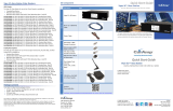
Kit Components
Description Item
Basic Unit
Viper SC+ IP Router
60 in. Cat 5 Ethernet Cable
Power Cable
2- and 3-
Piece Kit Additional Items
SMA Male to BNC Female
Connector
SMA Female to BNC Male
Connector
TNC Male to BNC Female
Connector
Mini Circuits 5 W 20 dB
Attenuator
Flex Rubber Duck Antenna
(VHF, UHF, or 900 MHz)
120 VAC to 13.8 VDC
4 A Power Supply
Product Documentation
http://help.calamp.com/files/references/manuals/Viper_SC_User_Manual.pdf
Any changes or modifications not expressly approved by the party responsible for compliance (in the country
where used) could void the user’s authority to operate the equipment.
CalAmp reserves the right to update its products, software, or documentation without obligation to notify any
individual or entity. Product updates may result in differences between the information provided and the
product shipped. For access to the most current product documentation and application notes, visit
www.calamp.com
.
Quick Start Guide
Viper SC+™
INTELLIGENT IP ROUTER FOR LICENSED SPECTRUM
© 2010-2013 CalAmp
PN 004-5008-000 Rev. B
Revised: March 2014

© 2010-2013 CalAmp
PN 004
-5008-000 Rev. B
All specifications are typical and
subject to change without notice.
CalAmp
1401 N
Rice Avenue
Oxnard,
CA 93030
t: 805.987.9000 | f: 805.987.8359
www.calamp.com
Setup and Configuration
These instructions allow you to set up a Viper SC+ IP Router to verify basic unit
operation and experiment with network designs and configurations. To
eliminate unnecessary disruption of traffic on the existing network while you
become familiar with the Viper SC+, you should use a network IP subnet
address that does not overlap with subnets currently in use in your test area.
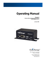
Antenna & Attenuator Connection
An Rx/Tx antenna is required for basic operation. Assemble antenna and
connectors as shown in the accompanying figure. Antenna and connectors are
sold separately.
Note: It is important to use attenuation between all demo units in the test
network to reduce the amount of signal strength in the test environment.
Device Connections
Refer to the diagram below for proper device connections.
Connect an Ethernet cable to the LAN port of the Viper SC+ and connect the other end
into the Ethernet port of your PC.
Primary power for the Viper SC+ must be within 10-30 V DC and must be capable of
providing:
10 W supply for Tx at 1 W
40 W supply for Tx at 5 W or
60 W supply for Tx at 10 W
Viper SC+ Demo kits include a power supply with spring terminals. Observe proper
polarity when connecting the cables to the power supply. The white wire must be
connected to the red wire or B+ supply, as shown in the above figure.
Accessing the Viper SC+ Web Server
The Viper SC+ is configured via a Web-browser interface and contains a DHCP server
which will automatically assign an IP address to your PC, however in some cases it may be
necessary to change the network settings on the PC to accept the IP address assigned by
the Viper DHCP server.
Step 1 Enable a network connection with the following LAN settings. In the Internet
Protocol (TCP/IP) Properties window, select Obtain an IP address automatically and
Obtain DNS server address automatically. Click OK and close.
Step 2 Open a Web browser and enter 192.168.205.1 in the Address bar. When the
connection Login window appears, enter the User name: Admin and the Password:
ADMINISTRATOR (both Admin and ADMINISTRATOR are case-sensitive) and click OK.
Viper SC+ Web Interface and Setup Wizard
Once you have logged in you will see the Home page of the Viper Web Interface as shown
in the following figure. Arranged vertically on the left side is the main navigation menu.
For quick setup, select Setup Wizard, the bottom selection of the main menu (to the left).
The introductory page of the Viper SC+ Setup Wizard is displayed as shown in the
following figure. Read the instructions carefully.
The Setup Wizard consists of five (5) steps. Each step is presented as a single page with a
few simple options to fill in or select from. Each of the five pages for each step of the Setup
Wizard contain the basic configuration settings that are most commonly required to select
or change to set up the Viper SC+ IP router for specific functionality.
Instructions for each of these steps are provided on the web page for the step.
The Setup Wizard steps are as follows
Step
Identification and function: Station Name and Mode settings: Station Name, IP
Forwarding Mode, Relay Point, Access Point, Multi-Speed Mode.
Step
Network Address & Subnet: IP Address, Network Mask, Default Gateway.
Step
Radio Settings: Bandwidth, Data and Control Packet Bit Rate, Rx & Tx Frequency
ranges , Tx Power.
Step
Encryption: Enable or Disable, and Encryption Pass Phrase.
Step
Setup completion: Apply / Save Configuration; if necessary, reboot / reset Viper.
Note: Some settings (indicated by a yellow alert symbol
) in the Setup Wizard web
pages require a reset of the Viper before they will take effect. If you change any of these
settings, be sure to reboot the Viper when you have finished the Setup Wizard.
Setup Wizard Quick Setup
Enter the following in the Setup Wizard for quick setup. Click Next as you complete each
page in sequence. (You can click Previous to review settings in a previous page if needed.)
Step
Assign a unique Station Name and select how unit will function.
- Station Name: Assign a unique Station Name
- IP Forwarding Mode: Bridge mode
- Relay Point: No
- Access Point: No
- Multi-Speed Mode: Disabled
Step
Default configuration — To monitor or change configuration remotely, each
unit requires a unique IP address. When configuring more than one unit, be
sure to increment IP addresses. (Enter this address in the browser after reset.)
- IP Address: 192.168.205.1 is the default setting; see above.
- Network Mask: 255.255.255.0
- Default Gateway: 0.0.0.0
Step
Verify FCC License before completing this step
- Bandwidth: Select channel bandwidth from drop-down menu
- Data and Control Bit Rate: Select rate from a down menu
- Rx Frequency: Enter Rx Frequency
- Tx Frequency: Enter Tx Frequency
- Tx Power: Enter 5 W
Step
Viper SC+ offers AES-128 bit encryption to protect your data from intrusion.
We recommend encryption be enabled for your wireless network. The
encryption phrase / key must be the same for all devices on your network.
- Encryption: Enabled
- Encryption Pass Phrase: Enter an encryption phrase
Step
Click Done. Your unit is now functioning in Bridge Mode.
Note: If you changed any parameters marked with the yellow alert symbol (
) you
must power-cycle the unit. Use the Reset link provided.
Check For Normal Operation
To simulate data traffic over the radio network, use the PC connected to the Viper SC+
Ethernet port to Ping each unit in the network multiple times. For more information
about configuring the Viper SC+, refer to the Viper SC+ User Manual (PN 001-5008-000).
Technical Support
For assistance with this product, contact CalAmp technical support.
Phone 1.507.833.6701, Option 2 for Fixed, Narrowband, and Radio Modem products
Or visit the Support section of our website at
http://www.calamp.com/support.
1401 North Rice Avenue
Oxnard, CA 93030
Tel: 1.805.987.9000
Fax: 1.805.987.8359.
ABOUT CALAMP
CalAmp is a leading provider of wireless communications products that enable anytime/anywhere
access to critical information, data and entertainment content. With comprehensive capabilities
ranging from product design and development through volume production, CalAmp delivers cost-
effective high quality solutions to a broad array of customers and end markets. CalAmp is the
leading supplier of Direct Broadcast Satellite (DBS) outdoor customer premise equipment to the
U.S. satellite television market. The Company also provides wireless data communication solutions

for the telemetry and asset tracking markets, private wireless networks, Interoperable Train Control
(ITC) radio transceivers for use in railroad Positive Train Control (PTC) applications, public safety
communications and critical infrastructure and process control applications. For additional
information, please visit the Company’s website at www.calamp.com
.
/