MICRO-EPSILON capaNCDT 6500 EtherCAT User manual
- Category
- Measuring & layout tools
- Type
- User manual

Operating Instructions
capaNCDT 6500
CS005
CS02
CSH02
CSH02FL
CS05
CSE05
CSE05/M8
CSH05
CSH05FL
CS08
CS1
CSE1
CSE1,25/M12
CSH1
CSH1FL
CS1HP
CSH1.2
CSH1.2FL
CS2
CSE2
CSE2/M16
CSH2
CSH2FL
CS3
CSE3/M24
CSH3FL
CS5
CS10
CSG0.50-CAm2.0
CSG1.00-CAm2.0

EtherCAT® is registered trademark and patented
technology, licensed by Beckhoff Automation GmbH,
Germany.
MICRO-EPSILON
MESSTECHNIK
GmbH & Co. KG
Koenigbacher Str. 15
94496 Ortenburg / Germany
Tel. +49/8542/168-0
Fax +49/8542/168-90
e-mail [email protected]
www.micro-epsilon.com

capaNCDT 6500
Contents
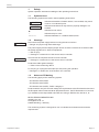
1. Safety .......................................................................................................................................... 5
1.1 Symbols Used .................................................................................................................................. 5
1.2 Warnings ........................................................................................................................................... 5
1.3 Notes on CE Marking ....................................................................................................................... 5
1.4 Intended Use .................................................................................................................................... 6
1.5 Proper Environment ......................................................................................................................... 6
2. Functional Principle, Technical Data ......................................................................................... 7
2.1 Measuring Principle .......................................................................................................................... 7
2.2 Structure ........................................................................................................................................... 7
2.2.1 Sensors .............................................................................................................................................. 8
2.2.2 Sensor Cable ..................................................................................................................................... 9
2.2.3 Preamplifier (DL6510 only) ................................................................................................................ 9
2.2.4 Preamplifier Cable (DL6510 only) ...................................................................................................... 9
2.2.5 Controller Housing ........................................................................................................................... 10
2.2.6 Oscillator .......................................................................................................................................... 10
2.2.7 DD6500 Display Board with Ethernet Interface ............................................................................... 11
2.2.8 Demodulator .................................................................................................................................... 11
2.3 Technical Data ................................................................................................................................ 12
3. Delivery ..................................................................................................................................... 13
3.1 Unpacking ...................................................................................................................................... 13
3.2 Storage ........................................................................................................................................... 13
4. Installation and Assembly ........................................................................................................ 14
4.1 Precautionary Measures ................................................................................................................. 14
4.2 Sensor............................................................................................................................................. 14
4.2.1 Radial Point Clamping with Grub Screw, Cylindric Sensors ........................................................... 14
4.2.2 Circumferential Clamping, Cylindric Sensors ................................................................................. 14
4.2.3 Flat Sensors ..................................................................................................................................... 14
4.2.4 Dimensional Drawing Sensors ........................................................................................................ 15
4.3 Sensor Cable .................................................................................................................................. 19
4.4 Preamplifier CP6001 and CPM6011 ............................................................................................... 20
4.5 Preamplifier Cable CAx .................................................................................................................. 21
4.6 Controller ........................................................................................................................................ 21
4.7 Power Supply ................................................................................................................................. 22
4.8 Ground Connection, Earthing ........................................................................................................ 22
4.9 Pin Assignment ............................................................................................................................... 23
4.10 Synchronization .............................................................................................................................. 24
5. Operation .................................................................................................................................. 25
5.1 Initial Operation .............................................................................................................................. 25
5.2 Basic Settings ................................................................................................................................. 25
5.2.1 DT6530 ............................................................................................................................................. 25
5.2.2 DD6530 ............................................................................................................................................ 25
5.2.3 DO6510 ............................................................................................................................................ 26
5.2.4 DL6530/6510 .................................................................................................................................... 27
5.3 Calibration with Metal Targets ........................................................................................................ 29
5.4 Linearity Adjustment and Calibration with Insulator Targets .......................................................... 30
5.5 Triggering ........................................................................................................................................ 32
5.6 Synchronization .............................................................................................................................. 32
6. Ethernet Interface ..................................................................................................................... 33
6.1 Hardware, Interface ........................................................................................................................ 33
6.2 Data Format of Measuring Values .................................................................................................. 35
6.3 Settings ........................................................................................................................................... 35
6.4 Commands ..................................................................................................................................... 36
6.4.1 Data Rate (SRA = Set Sample Rate) ............................................................................................... 37
6.4.2 Trigger Mode (TRG) ......................................................................................................................... 37
6.4.3 Get Measured Data (GMD) .............................................................................................................. 38
6.4.4 Averaging Type (AVT) ...................................................................................................................... 38
6.4.5 Dynamic Noise Rejection ................................................................................................................. 39
6.4.6 Averaging Number (AVN) ................................................................................................................ 39
6.4.7 Channel Status (CHS)...................................................................................................................... 39
6.4.8 Channel Transmit (CHT) .................................................................................................................. 39
6.4.9 Mode of Linearization (LIN).............................................................................................................. 40
6.4.10 Set Linearization Point (SLP) ........................................................................................................... 40

capaNCDT 6500
6.4.11 Get Linearization Point (GLP) .......................................................................................................... 41
6.4.12 Status (STS) ..................................................................................................................................... 41
6.4.13 Version (VER) ................................................................................................................................... 41
6.4.14 Display Setups (DIS) ........................................................................................................................ 41
6.4.15 Load Factory Setting (FDE) ............................................................................................................. 42
6.4.16 SMF = Set Mathematic Function (SMF) ......................................................................................... 42
6.4.17 Get Mathematic Function (GMF) ..................................................................................................... 43
6.4.18 Clear Mathematics Function (CMF ) ................................................................................................ 43
6.4.19 Ethernet Settings (IPS = IP-Settings) .............................................................................................. 43
6.4.20 Change between Ethernet and EtherCAT (IFC = Interface) ........................................................... 43
6.4.21 Query Data Port (GDP = Get Dataport) .......................................................................................... 44
6.4.22 Set Data Port (SDP = Set Dataport) ................................................................................................ 44
6.4.23 Access Channel Information (CHI = Channel info) ........................................................................ 44
6.4.24 Access Controller Information (COI = Controller info) ................................................................... 44
6.4.25 Login for Web Interface (LgI = Login) ............................................................................................. 44
6.4.26 Logout for Web Interface (LGO = Logout) ...................................................................................... 44
6.4.27 Change Password (PWD = Password) ........................................................................................... 45
6.4.28 Change Language for the Web Interface (LNG = Language) ........................................................ 45
6.4.29 Write Measuring Range Information in Channel (MRA = Measuring Range) ................................ 45
6.4.30 Default Messages ............................................................................................................................ 45
6.5 Control via Ethernet ........................................................................................................................ 46
6.5.1 Requirements ................................................................................................................................... 46
6.5.2 Access via Web Interface ................................................................................................................. 47
6.6 Firmware Update ............................................................................................................................ 47
7. EtherCAT Interface ................................................................................................................... 47
7.1 Introduction..................................................................................................................................... 47
7.2 Change Interface ............................................................................................................................ 48
8. Operation and Maintenance .................................................................................................... 48
9. Liability for Material Defects .................................................................................................... 49
10. Decommissioning, Disposal .................................................................................................... 49
A 1 Optional Accessory .................................................................................................................. 50
A 2 Services .................................................................................................................................... 52
A 3 Factory Setting ......................................................................................................................... 52
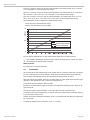
A 4 Tilt Angle Influence on the Capacitive Sensor ....................................................................... 52
A 4.1 Measurement on Narrow Targets ................................................................................................... 52
A 4.2 Measurements on Balls and Shafts ............................................................................................... 53
A 5 EtherCAT Documentation ........................................................................................................ 54
A 5.1 Preamble ........................................................................................................................................ 54
A 5.1.1 Structure of EtherCAT®-Frames .................................................................................................... 54
A 5.1.2 EtherCAT® Services ....................................................................................................................... 54
A 5.1.3 Addressing and FMMUs ................................................................................................................. 55
A 5.1.4 Sync Manager ................................................................................................................................ 55
A 5.1.5 EtherCAT State Machine ................................................................................................................ 56
A 5.1.6 CANopen over EtherCAT ................................................................................................................ 56
A 5.1.7 Process Data PDO Mapping .......................................................................................................... 56
A 5.1.8 Service Data SDO Service .............................................................................................................. 57
A 5.2 CoE – Object Directory ................................................................................................................... 57
A 5.2.1 Communication Specific Standard Objects (CiA DS-301) ............................................................ 57
A 5.2.2 Manufacturer Specific Objects ....................................................................................................... 58
A 5.3 Measurement Data Format ............................................................................................................. 61
A 5.4 EtherCAT Configuration with the Beckhoff TwinCAT©-Manager ................................................... 61
A 6 Thickness Measurement .......................................................................................................... 64
A 6.1 General ........................................................................................................................................... 64
A 6.2 Define Sensor Measuring Ranges ................................................................................................. 64
A 6.3 Data Format, Word Length ............................................................................................................. 65
A 6.4 Set Math Functions ......................................................................................................................... 65
A 6.5 Interpretation of the Measuring Values .......................................................................................... 66
A 6.6 Example .......................................................................................................................................... 66

Safety
capaNCDT 6500 Page 5
1. Safety
System operation assumes knowledge of the operating instructions.
1.1 Symbols Used
The following symbols are used in these operating instructions:
CAUTION
Indicates a hazardous situation which, if not avoided, may result
in minor or moderate injuries.
NOTICE
Indicates a situation that may result in property damage if not
avoided.
Indicates a user action.
i
Indicates a tip for users.
Measure
Indicates hardware or a software button/menu.
1.2 Warnings
Disconnect the power supply before touching the sensor surface.
> Danger of injury through static discharge
The power supply and the display/output device must be connected in accordance with
the safety regulations for electrical equipment.
> Risk of injury
> Damage to or destruction of the sensor and/or controller
Avoid shocks and impacts the sensor and controller.
> Damage to or destruction of the sensor and/or controller
Protect the cable against damage.
> Failure of the measuring device
Do not plug or unplug the board (Europe size) during the operation.
> Damage to or destruction of the board in the controller
1.3 Notes on CE Marking
The following apply to the measuring system:
- EU directive 2014/30/EU
- EU directive 2014/35/EU
- EU directive 2011/65/EU, “RoHS“ category 9
Products which carry the CE mark satisfy the requirements of the EU directives cited and
the European harmonized standards (EN) listed therein. The EU Declaration of Conformi-
ty is available to the responsible authorities according to EU Directive, article 10, at:
MICRO-EPSILON MESSTECHNIK
GmbH & Co. KG
Koenigbacher Str. 15
94496 Ortenburg / Germany
The measuring system is designed for use in industrial environments and meets the
requirements.
CAUTION
NOTICE

capaNCDT 6500 Page 6
Safety
1.4 Intended Use
The DT6530 measuring system is designed for use in industrial and laboratory areas.
It is used for
- displacement, distance, profile, thickness and surface measurement
- for in-process quality control and dimensional testing
The system must only be operated within the limits specified in the technical data, see
Chap. 2.3.
The system must be used in such a way that no persons are endangered or machines
and other material goods are damaged in the event of malfunction or total failure of the
system/sensor/controller.
Take additional precautions for safety and damage prevention in case of safety-related
applications.
1.5 Proper Environment
- Protection class sensor, sensor cable, preamplifier: IP 54 (applies only for connected
sensor cable)
- Protection class controller: IP 40
- The space between the sensor surface and the target must have an unvarying dielec-
tric constant
- The space between the sensor surface and the target may not be contaminated (for
example water, rubbed-off parts, dust, et cetera)
- Operating temperature
Sensor: -50 to +200 °C (-58 to +392 °F)
Sensor cable: -100 to +200 °C (-58 to +392 °F) (CCmx and CCmx/90)
-20 to +80 °C (-4 to +176 °F)
(CCgx and CCgx/90 - permanently)
-20 to +100 °C (-4 to +212 °F)
(CCgx and CCgx/90 - 10,000 h)
Controller, preamplifier: +10 to +60 °C (+50 to 140 °F)
- Humidity: 5 - 95 % (non-condensing)
- Ambient pressure: atmospheric pressure
- Storage temperature:
Sensor cable: -50 ... +200 °C (-58 to +392 °F) (CCmx and CCmx/90)
-50 ... +80 °C (-58 to +176 °F) (CCgx and CCgx/90)

Functional Principle, Technical Data
capaNCDT 6500 Page 7
2. Functional Principle, Technical Data
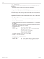
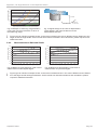
2.1 Measuring Principle
The principle of capacitive distance measurement with the capaNCDT system is based
on the principle of the parallel plate capacitor. For conductive targets, the sensor and
the target opposite form the two plate electrodes. If a AC current with a constant ampli-
tude flows through the sensor capacitor, the amplitude of the AC voltage at the sensor is
proportional to the distance between the capacitor electrodes. The AC voltage is demod-
ulated, amplified and output as an analog signal. The capaNCDT system evaluates the
reactance X
c
of the plate capacitor which changes strictly in proportion to the distance.
X
c
= ; Capacitance C =
o
r
1
jC
area
d
This theoretical relationship is realized almost ideally in practice by designing the sen-
sors as guard ring capacitors.
Mesauring object: electrical conductor
Ground
Screening electrode (guarding)
Measuring electrode
d
U
c
Fig. 1 Structure of a capacitive sensor
The linear characteristic of the measuring signal is achieved for electrically conductive
target materials (metals) without any additional electronic linearization. Slight changes in
the conductivity or magnetic properties do not affect the sensitivity or linearity.
i
A small target and bent (uneven) surfaces cause a nonlinear characteristic.
The DT6530 system also measures reliably against insulating materials. The linear be-
havior for this category of targets is achieved by special electronic circuitry. A constant
relative dielectric of the material is, however, a prerequisite for accurate measurement.
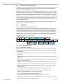
2.2 Structure
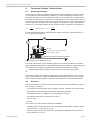
The multi-Channel non-contact, single-channel measuring system installed in an alumi-
num housing, consists of:
- Controller housing with power supply, display, ethernet, oscillator and analog output
- Demodulator board (Europe size) (DL6510 respectively DL 6530)
- Preamplifier CP6001 or CPM6011 (only necessary for DL6510)
- Preamplifier cable (only necessary for DL 6510)
- Sensor cable
- Sensor
Two versions of the demodulator boards are available:
- DL6530: Signal conditioning electronics with integrated preamplifier, distance sensor
and controller: 1.4 m (4.6 ft) / 2 m (6 ft)
- DL6510: Signal conditioning electronics with external preamplifier, distance sensor
and controller: up to 40 m

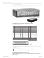
capaNCDT 6500 Page 8
Functional Principle, Technical Data
Ethernet/EtherCAT
Display
230VAC
100VAC
Sensors
Sensor cables
Preamplifier
Demodulator
DL 6510
Demodulator
DL 6510
Demodulator
DL 6510
Demodulator
DL 6510
Demodulator
DL 6530
Demodulator
DL 6530
Demodulator
DL 6530
Demodulator
DL 6530
1 2 3 4 5 6 7 8
Connecting cables
Mains
± 15VDC Power-
+ 5VDC supply
Oscillator
Ch 2 Ch 4 Ch 5 Ch 6 Ch 7 Ch 8
Signal output socket
Sub-D, 37-pin
Ch 1 Ch 3
Fig. 2 Block diagram DT6530c (2 channels), block diagram DT6530 (8 channels)
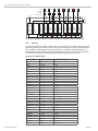
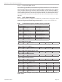
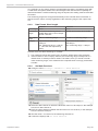
2.2.1 Sensors
For this measurement system, several sensors can be used. In order to obtain accurate
measuring results, the surface of the sensor must be kept clean and free from damage.
The capacitive measuring process is area-related. A minimum area (see table) is re-
quired depending on the sensor model and measuring range. In the case of insulators
the dielectric constant and the target thickness also play an important role.
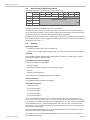
Sensors for metal targets
Sensor model Measuring range Min. target diameter
CS005 0.05 mm 3 mm
CS02 0.2 mm 5 mm
CS05 0.5 mm 7 mm
CS08 0.8 mm 9 mm
CS1 1 mm 9 mm
CS1HP 1 mm 9 mm
CS2 2 mm 17 mm
CS3 3 mm 27 mm
CS5 5 mm 37 mm
CS10 10 mm 57 mm
CSE05 0.5 mm 6 mm
CSE05/M6 0.5 mm 6 mm
CSE1 1 mm 8 mm
CSE1,25/M12 1.25 mm 10 mm
CSE2 2 mm 14 mm
CSE2/M16 2 mm 14 mm
CSE3/M24 3 mm 20 mm
CSG0,50-CAm2,0 0.5 mm ca. 7 x 8 mm
CSG1,00-CAm2,0 1 mm ca. 8 x 9 mm
CSH02 0.2 mm 7 mm
CSH05 0.5 mm 7 mm
CSH1 1 mm 11 mm
CSH1,2 1.2 mm 11 mm
CSH2 2 mm 17 mm
CSH02FL 0.2 mm 7 mm
CSH05FL 0.5 mm 7 mm
CSH1FL 1 mm 11 mm
CSH1,2FL 1.2 mm 11 mm
CSH2FL 2 mm 17 mm
CSH3FL 3 mm 24 mm

Functional Principle, Technical Data
capaNCDT 6500 Page 9
Sensors for insulating targets
The sensors also measure reliable against insulating materials. The linear behavior for
this category of targets is achieved by special linearization, see Chap. 5.4. The measur-
ing ranges of the respective sensors depend on the e
r
of the target.
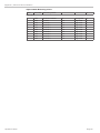
2.2.2 Sensor Cable
Model Cable length Cable ø 2 axial
connector
1x axial
+ 1x 90
0
For sensors Min. bending
radius
once
perma-
nently
CCgxC 2/4/6 or 8 m 3.1 mm
•
0.05 - 0.8 mm
10 mm 22 mm
CCgxC/90 2/4/6 or 8 m 3.1 mm
•
0.05 - 0.8 mm
CCgxB 2/4/6 or 8 m 3.1 mm
•
1 ... 10 mm
CCgxB/90 2/4/6 or 8 m 3.1 mm
•
1 ... 10 mm
CCmxC 1.4/2.8 or 4.2 m 2.1 mm
•
0.05 - 0.8 mm
7 mm 15 mm
CCmxC/90 1.4/2.8 or 4.2 m 2.1 mm
•
0.05 - 0.8 mm
CCmxB 1.4/2.8 or 4.2 m 2.1 mm
•
1 ... 10 mm
CCmxB/90 1.4/2.8 or 4.2 m 2.1 mm
•
1 ... 10 mm
The sensor and controller respectively sensor and preamplifier are connected by a spe-
cial, double screened, 2 m (7.87 inches) / 1.4 m (5.5 inches) long sensor cable. Sensor
cables with 8 m (31.50 inches) / 4.2 m (16.53 inches) length are with a special adjust-
ment of the controller possible. The user must not shorten or lengthen these special
cables. Usually, a damaged cable can not be repaired.
i
Switch off the device when plugging and removing connectors.
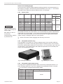
2.2.3 Preamplifier (DL6510 only)
The preamplifier is necessary as connector between sensor and controller. With this
preamplifier it is possible to deal with greater distances between sensor and controller.
The sensor cable length is fixed at 2 m (7.87 inches) / 1.4 m (5.5 inches), (up to max. 8 m
(31.50 inches) / 4.2 m (16.53 inches) with additional adjustment of the controller) and
must not be modified by the user.
Fig. 3 Preamplifier CP6001 Fig. 4 Preamplifier CP6011
2.2.4 Preamplifier Cable (DL6510 only)
The drag-chain compatible preamplifier cable connects the preamplifier with the con-
troller. It bridges distances of up to 40 m between the preamplifier and the controller.
Do not shorten or lengthen these special cables.
Model Cable Length
Min. bending radius, permanent
CA5 5 m
33 mm
CA10 10 m
CA20 20 m
CA25 25 m
CA30 30 m
CA40 40 m
NOTICE
Do not crush the sensor
cable. Do not modify the
sensor cable.
Both leads to a loss of
functionality.
Install the sensor cable in
a protected area.

capaNCDT 6500 Page 10
Functional Principle, Technical Data
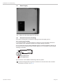
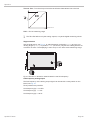
2.2.5 Controller Housing
The capaNCDT 6500 multichannel rack is constructed for up to eight channels, the
capaNCDT 6500C multichannel rack is constructed for up to two channels which are all
synchronized.
Power supply
Display board
Demodulator
Fig. 5 Front view DT6530
Mains connection Ground connection
Fig. 6 Rear view DT6530
Fig. 7 Front view DT6530C
2.2.6 Oscillator
The oscillator supplies all measuring channels (sensors) with constant frequency- and
amplitude- stable alternating current. The frequency is 31 kHz. As all the sensors were
supplied by an oscillator, it comes not to an disturbing interference of the channels one
below the other. Every second measuring channel receives an oscillator signal phase
displaced by 180 °.
NOTICE
Output voltage can reach
up 14 VDC if there is no
sensor connected or
target out of measuring
range.

Functional Principle, Technical Data
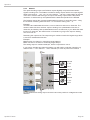
capaNCDT 6500 Page 11
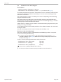
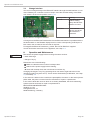
2.2.7 DD6500 Display Board with Ethernet Interface
The display board DD6500 serves to display and output of signal. The measuring val-
ues can be read in percent of all eight channels on display. The analog output signals
(voltage and current output) the trigger input and the synchronization input/output are
located on the 37-pol-Sub-D connector. The system can be connected to a network
through a Ethernet interface and the measuring values can be read out digital, see Chap.
6. - Ethernet Interface. In addition, the display board contains an EtherCAT interface for
transmission of the measured values in real time.
Fig. 8 Display board
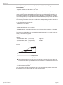
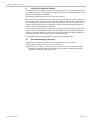
2.2.8 Demodulator
Demodulation, linearization and amplifying of the distance-dependent measuring signal
are tasks of the demodulation-unit. The three trim-pots allow a
- Linearity
- Gain
- Zero
adjustment of measuring system, see Chap. 5.3, see Chap. 5.4.
Fig. 9 Demodulator board DL 6510

capaNCDT 6500 Page 12
Functional Principle, Technical Data
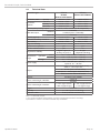
2.3 Technical Data
Controller type DT6530
DL6530
DL6510 with CP6001
DT6530
DL6510 mit CPM6011
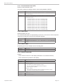
Resolution, static (2.6 Hz) 0.000075 % FSO 0.0006 % FSO
Resolution,
dynamic
(100 Hz) 0.0003 % FSO 0.0025 % FSO
(1 kHz) 0.0009 % FSO 0.007 % FSO
(8.5 kHz) 0.002 % FSO 0.015 % FSO
Limit frequency analog output 20 Hz; 1 kHz; 8.5 kHz (-3 dB, adjustable)
Data rate output
Ethernet
3.9 kSa/s
7.8 kSa/s (max. 4 channels)
EtherCAT 2.0 kSa/s
Linearity (typical) ±0.025 % FSO ±0.05 % FSO
Maximum sensitivity deviation ±0.05 % FSO ±0.1 % FSO
Repeatability
1
0.0003 % FSO 0.001 % FSO
Long time stability ±0.002 % FSO / month ±0.02 % FSO / month
Synchronous operation
2
yes yes
Insulator measurement yes no
Temperature stability
digital: 5 ppm/°C
analog: 10 ppm/°C
80 ppm
(digital and analog)
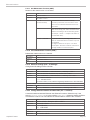
Temperature
range
operation
sensor -50 ... +200 °C (-58 ... +392 °F)
controller +10 ... +60 °C (+50 ...+140 °F)
storage -10 ... +75 °C (+14 ... +167 °F)
Power supply
100 ... 240 VAC (50 ... 60 Hz)
optional: 18 ... 36 VDC
Output
0 ... 10 V (max. 10 mA, short circuit proof);
offset ≤ ±10 V up to 0 V
4 ... 20 mA (max. load 500 Ohm)
optional: 0 ... 20 mA (max. load 500 Ohm)
Ethernet 24 bit / EtherCAT 24 bit
Sensors all sensors are suitable
Sensor cable length, standard
CCm1.4x
CCg2.0x
Sensor cable length, matched
≤ 4.2 m (type CCmx)
≤ 8.0 m (type CCgx)
≤ 2.8 m (type CCmx)
≤ 4 m (type CCgx)
Trigger TTL, 5 V
Humidity 5 ... 95 % (non-condensing)
Protection class IP 40 (controller and sensors)
FSO = Full Scale Output
1) at constant ambient temperature (including temperature and air humidity)
2) Possible to further Controller DT6530 resp. DT6530C

Delivery
capaNCDT 6500 Page 13
3. Delivery
3.1 Unpacking
1 Housing with power supply, oscillator and display board
n Demodulators
n Sensors
n Sensor cable with connector
n Preamplifier (only DL6510)
n Preamplifier cable (only DL6510)
1 Instruction manual
37-pole Sub-D connector, mains connection cable, network cable (crossover cable)
CD with Runtime-version/MEDAQlib (Ethernet), SensorFinder, ESI file (EtherCAT)
n = Number of displacement measuring channels
Remove the parts of the system carefully from the packaging and transport them in
such a way that they are not damaged.
Check for completeness and shipping damages immediately after unpacking.
In case of damage or missing parts, please contact the manufacturer or supplier.
3.2 Storage
Temperature range storage: -10 ° ... +75 °C (+14 ... 167 °F)
Humidity: 5 - 95 % (non-condensing)

capaNCDT 6500 Page 14
Installation and Assembly
4. Installation and Assembly
4.1 Precautionary Measures
No sharp-edged or heavy objects may get into contact with the sensor cable sheath.
Protect the cable In pressurized rooms against pressure loads.
Avoid kinks in any case. Check the connections for tight fit.
i
A damaged cable cannot be repaired.
4.2 Sensor
The sensors may be mounted free-standing or flush.
When assembling, make sure that the polished sensor surface is not scratched.
4.2.1 Radial Point Clamping with Grub Screw, Cylindric Sensors
This simple type of fixture is only recommended for a force and vibration-free installation
position. The grub screw must be made of plastic so that it cannot damage or deform
the sensor housing.
Grub screw
Fig. 10 Radial point clamping with grub screw.
i
Do not use metal grub screws
> Danger of damaging the sensor
4.2.2 Circumferential Clamping, Cylindric Sensors
This sensor mounting option offers maximum reliability because the sensor is clamped
around its cylindrical housing. It is absolutely necessary in difficult installation environ-
ments, for example on machines, production plants et cetera.
Mounting with
clamping ring
Fig. 11 Circumferential clamping
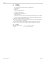
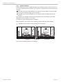
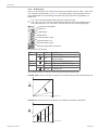
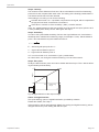
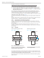
4.2.3 Flat Sensors
Flat sensors are mounted by means of a tap hole for M2 (in case of sensors 0.2 and
0.5 mm) or by a through hole for M2 screws. The sensors can be bolted on top or below.
Screwing from above Screwing from bottom

Installation and Assembly
capaNCDT 6500 Page 15
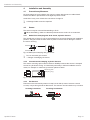
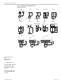
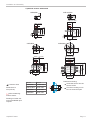
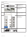
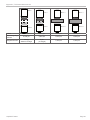
4.2.4 Dimensional Drawing Sensors
Cylindric sensors
CS02
12
(.472)
ø6f7 (.236 dia.)
12
(.472)
CS005
ø6f7
(.236 dia.)
ø3 (0.118 dia.)
ø8f7 (.314 dia.)
CS05
12
(.472)
11 (.433)
CSE05
12 (.47)
ø6f7
(.24 dia.)
ø5.7 (.22)
15 (.59)
ø10h7
(.394 dia.)
CS08
9 (.35)
M=1:2
ø20h7 (.79 dia.)
24
-0.2
(.945)
-0.008
CS2
CS1
CSE1
12 (0.47)
ø8f7 (0.31 dia.)
ø10h7 (.394 dia)
ø10h7 (.394 dia.)
CS1HP
20
-0.2
(.787
-0.008
)
CSE2
ø14h7 (0.55 dia.)
18.5 (0.73)
22 (0.87)
21
-0.2
(o.83
-0.008)
ø7.7 (0.30 dia.)
9 (0.35)
ø13.7 (0.54 dia.)
ø30h7 (1.18 dia.)
ø20h7 (.79 dia.)
24
-0.2
(.945)
-0.008
CS3
M=1:2
ø20h7 (.79 dia.)
ø40h7 (1.58 dia.)
CS5
M=1:2
ø20h7 (.79 dia.)
ø60h7 (2.36 dia.)
M=1:2
CS10
16.5
(
.649)
16.5
(.649)
24
-0.2
(.945)
-0.008
24
-0.2
(0.94
-0.008
)
16.5
(0.65)
Connector side
Dimensions in
mm (inches)
x = cable length in m
Circumferential clamping
possible beginning 3
mm behind the sensor
surface.
Drawings of other sen-
sors are available upon
request.

capaNCDT 6500 Page 16
Installation and Assembly
ø12g6 (.473 dia.)
CSH1-CAmx
CSH1.2-CAmx
14
(.39)
33
(1.30)
ø11.5
(.45 dia.)
10 (.39)
ø
2.2 (.09 dia.)
ca. 37 (1.46)
ca. 9.4 (.37)
ø8g6 (.315 dia.)
CSH02-CAmx
CSH05-CAmx
ø7.5
(.30 dia.)
14
(.39)
33
(1.30)
10 (.39)
ø
2.2 (.09 dia.)
ca. 37 (1.46)
ca. 9.4 (.37)
ø
2.2
(.09)
appr. 37 (1.5)
appr. 9.4
(.37)
ø20g6 (.79)
10 (.39)
14 (.55)
33 (1.3)
ø19.5 (.77)
CSH2-CAmx
Connector side
Dimensions in
mm (inches)
Circumferential clamping
possible beginning 3
mm behind the sensor
surface.
Drawings of other sen-
sors are available upon
request.

Installation and Assembly
capaNCDT 6500 Page 17
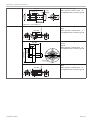
Cylindrical sensors with thread
CSE05/M8
14.0
17.0 (.67)
+0.1
-0.2
13.4 WS6
3.0
(.12)
ø5.7
ø6.0
(.24 dia.)
M8x0.5
CSE1,25/M12
18.5
22.0 (.87)
17.6
ø9.7
ø10
ø10.4 (.41 dia.)
M12x1
4.0
(.16)
WS10
CSE2/M16 CSE3/M24
18.5
22.0 (.87)
17.6
25.5
30.0 (1.18)
24.6
M16x1
M24x1.5
4.0
(.16)
5.0
(.20)
ø13.7
ø14.0
ø14.4 (.57 dia.)
ø19.2
ø20.0
ø20.6 (.81 dia.)
6.0
(.24)
10.0
(.39)
WS14
WS18
Sensor Torque
Preferred mounting:
Screw the sensor into the
sensor holder.
Turn the mounting nut on.
Do not exceed torques.
CSE05/M8 2.5 Nm max.
CSE1,5/M12 10 Nm max.
CSE2/M16 20 Nm max.
CSE3/M24 70 Nm max.
Connector side
Dimensions in
mm (inches)
Active measuring
surface sensor
Drawings of other sen-
sors are available upon
request.

capaNCDT 6500 Page 18
Installation and Assembly
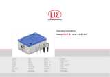
Flat sensors
M2
3.5
(.14)
4
(.16)
5.5
(.22)
R4 (.16)
CSH02FL-CRmx
CSH05FL-CRmx
6.5
(.25)
4 (.16)
0.1 (.003)
ø3
(.12 dia.)
1.75
(.07)
ø2.2
(.09)
appr. 37 (1.46)
ca. 9.4 (.37)
CSH1FL-CRmx
CSH1.2FL-CRmx
11 (.43)
2.25
(.09)
4.5
(.18)
5
(.20)
7.5
(.29)
R6
(.24)
ø3
(.12 dia.)
0.1
(.003)
4 (.16)
ø2.5
(.10)
ø4
(.16 dia.)
ø2.2
(.09)
appr. 37 (1.46)
ca. 9.4 (.37)
15.5 (.61)
ø3
(.12)
ø2.2
(.09)
0.1
(.003)
20 (.79)
5
(.20)
1.6
(.06)
ø4
(.16)
ø2.2
(.09)
ca. 9.4
(appr. .37)
15.5 (.61)
20 (.79)
7.6
(.30)
appr. 37 (appr. 1.46)
CSH2FL-CRmx
ø2,2
(.09)
0,1
(.003)
5
(.20)
2,2
(.09)
ø4
(.16)
ø2,2
(.09)
ca. 9,4
(appr. .37)
20 (.79)
25 (.98)
ca. 37 (appr. 1.46)
20 (.79)
25 (.98)
ø3
(.12)
7,6
(.30)
CSH3FL-CRmx
200 (7.87)
9.9 (0.39)
15
(0.59)
20.2 (0.80)
1 (0.04)
Sensor structures
Thickness 0.9
-0.05
(0.04
-0.002
)
216 (8.5)
R2
CSG0.50-CAm2.0 and CSG1.00-CAm2.0
Sensor structures
2.9
(0.11)
4.2 (0.17)
4.5
(0.18)
5.4
(0.21)
4.2 (0.17)
6.2 (0.24)
3.85
(0.15)
4.4
(0.17)
CSG0.50-CAm2.0 CSG1.00-CAm2.0
Dimensions in mm (inches), not to scale

Installation and Assembly
capaNCDT 6500 Page 19
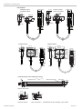
4.3 Sensor Cable
The sensor is connected to the signal conditioning electronics by the sensor cable. The con-
nection is made by simple plugging. The connector locks automatically. The tight fit can be
checked by pulling the connector housing (cable bushing). The lock can be released and the
connector can be opened by pulling the knurled housing sleeve of the cable bushing.
Sensor cable CCgxC
Ø9.4 (.37)
Cable length x
17.5 (.69)
13.7 (.54)
8.6 (.34)
Ø6 (.24)
Ø5.4 (.21)
Ø3.1
36.5 (1.44)
26.5 (1.04)
Ø7 (.28)
Sensor cable CCgxC/90
Ø3.1 (.12)
21 (.83)
Ø6 (.24)
Ø5.4 (.21)
8 (.31)
13.1
(.52)
16.9 (.67)
Sensor cable CCgxB
Cable length x
Ø3.1
(.12)
26.5 (1.04)
36.5 (1.44)
Ø7 (.28)
Ø9.4 (.37)
Sensor cable CCgxB/90
Ø8.9
(.35)/SW7
25 (.98)
20.5 (.81)
30.5 (1.20)
Ø7(.28)
Ø10 (.39)
Ø9.4 (.37)
Cable length x
17.5
(.69)
13.7 (.54)
8.6 (.34)
Ø6 (.24)
Ø5.4 (.21)
Ø2.1
37 (1.46)
27 (1.06)
Ø7 (.28)
Sensor cable CCmxC
Sensor cable CCmxC/90
Ø3.1 (.12)
21 (.83)
Ø6 (.24)
Ø5.4 (.21)
8 (.31)
13.1
(.52)
16.9 (.67)
Cable length x
Ø2.1
(.08)
27 (1.06)
37 (1.46)
Ø7 (.28)
Ø9.4 (.37)
Sensor cable CCmxB
Sensor cable CCmxB/90
Ø8.9
(.35)/SW7
25 (.98)
20.5 (.81)
30.5 (1.20)
Ø7(.28)
Ø10 (.39)
Model Cable length Cable ø 2 axial
connector
1x axial
+ 1x 90
0
For sensors Min. bending radius
once permanently
CCgxC 2/4/6 or 8 m 3.1 mm
•
0.05 - 0.8 mm
10 mm 22 mm
CCgxC/90 2/4/6 or 8 m 3.1 mm
•
0.05 - 0.8 mm
CCgxB 2/4/6 or 8 m 3.1 mm
•
1 ... 10 mm
CCgxB/90 2/4/6 or 8 m 3.1 mm
•
1 ... 10 mm
CCmxC 1.4/2.8 or 4.2 m 2.1 mm
•
0.05 - 0.8 mm
7 mm 15 mm
CCmxC/90 1.4/2.8 or 4.2 m 2.1 mm
•
0.05 - 0.8 mm
CCmxB 1.4/2.8 or 4.2 m 2.1 mm
•
1 ... 10 mm
CCmxB/90 1.4/2.8 or 4.2 m 2.1 mm
•
1 ... 10 mm

capaNCDT 6500 Page 20
Installation and Assembly
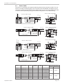
4.4 Preamplifier CP6001 and CPM6011
Sensor
Controller
34.6
(1.36)
85.6 (3.37)
73 (2.87)
42 (1.65)
11.5
(453)
114 (4.49)
8 (.36)
4.5 (.18)
Fig. 12 Preamplifier CP6001
CONTROLLERSENSOR
39.4 (1.55)
55 (2.16)
67 (2.64)6.5(.25) 25 (1.02)
80 (3.15)
Fig. 13 Preamplifier CPM6011
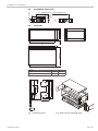
Mounting preamplifier with mounting device (CP6001)
Remove the four black protecting caps at the housing screws, dimension 73.
Remove the four housing screws.
Fix the both mounting devices at the preamplifier. Use the screws contained in the
delivery.
2.5 x 45°
(.1 x 45°)
Ø3.2
(Ø.13)
R2
(.078)
19.3
(.80)
7
(.3)
61.4 (2.40)
73 (2.90)
84.6 (3.30)
15
(.60)
25
(1.00)
2
(.08)
Ø4.2
(Ø.16)
78.8 (3.10)
9.8 (.39)
5.8 (.23)
8.5 (.34)
4.2
(.16)
Fig. 14 Mounting device for preamplifier
Dimensions in mm (inches), not to scale.
Page is loading ...
Page is loading ...
Page is loading ...
Page is loading ...
Page is loading ...
Page is loading ...
Page is loading ...
Page is loading ...
Page is loading ...
Page is loading ...
Page is loading ...
Page is loading ...
Page is loading ...
Page is loading ...
Page is loading ...
Page is loading ...
Page is loading ...
Page is loading ...
Page is loading ...
Page is loading ...
Page is loading ...
Page is loading ...
Page is loading ...
Page is loading ...
Page is loading ...
Page is loading ...
Page is loading ...
Page is loading ...
Page is loading ...
Page is loading ...
Page is loading ...
Page is loading ...
Page is loading ...
Page is loading ...
Page is loading ...
Page is loading ...
Page is loading ...
Page is loading ...
Page is loading ...
Page is loading ...
Page is loading ...
Page is loading ...
Page is loading ...
Page is loading ...
Page is loading ...
Page is loading ...
Page is loading ...
Page is loading ...
-
 1
1
-
 2
2
-
 3
3
-
 4
4
-
 5
5
-
 6
6
-
 7
7
-
 8
8
-
 9
9
-
 10
10
-
 11
11
-
 12
12
-
 13
13
-
 14
14
-
 15
15
-
 16
16
-
 17
17
-
 18
18
-
 19
19
-
 20
20
-
 21
21
-
 22
22
-
 23
23
-
 24
24
-
 25
25
-
 26
26
-
 27
27
-
 28
28
-
 29
29
-
 30
30
-
 31
31
-
 32
32
-
 33
33
-
 34
34
-
 35
35
-
 36
36
-
 37
37
-
 38
38
-
 39
39
-
 40
40
-
 41
41
-
 42
42
-
 43
43
-
 44
44
-
 45
45
-
 46
46
-
 47
47
-
 48
48
-
 49
49
-
 50
50
-
 51
51
-
 52
52
-
 53
53
-
 54
54
-
 55
55
-
 56
56
-
 57
57
-
 58
58
-
 59
59
-
 60
60
-
 61
61
-
 62
62
-
 63
63
-
 64
64
-
 65
65
-
 66
66
-
 67
67
-
 68
68


MICRO-EPSILON capaNCDT 6500 EtherCAT User manual
- Category
- Measuring & layout tools
- Type
- User manual
Ask a question and I''ll find the answer in the document
Finding information in a document is now easier with AI
Related papers
-
MICRO-EPSILON CSE2-M16 Operating Instructions Manual
-
 MICRO-EPSILON capaNCDT 6222 User manual
-
 MICRO-EPSILON capaNCDT 6112 User manual
-
 MICRO-EPSILON capaNCDT 6200 User manual
-
 MICRO-EPSILON capaNCDT 6228 / 6238 Operating instructions
-
 MICRO-EPSILON capaNCDT 6110/6120 User manual
-
 MICRO-EPSILON capaNCDT 6019 Owner's manual
-
 MICRO-EPSILON eddyNCDT 3001 - U2 Assembly Instructions
-
 MICRO-EPSILON capaNCDT 6200 / 6222 Quick Manual
-


Other documents
-
Kmart 43105908 User manual
-
IFM AC5210 Installation guide
-
ICP ECAT-2611 Quick Start
-
ICP DAS USA ECAT-2610 Quick Start
-
-
Samsung SDP-6500DX Owner's manual
-
YSI WL430 Wastewater Level Sensor Quick start guide
-
 halstrup-walcher PS 32 EC Series User manual
-
ICP DAS USA ECAT-M801-8AX-S User manual
-
