Page is loading ...

LLL1
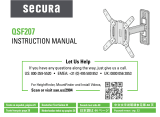
Instruction Manual
Recommended placement
Our US-based
install experts
are standing
by to help.
Call us at:
1-855-734-7805
Get it right the
first time.
HeightFinder
™
shows you
where to drill.
Check it out at:
SANUS.com/2850
Want to watch a
video that shows
how easy this DIY
project will be?
Watch it now at:
SANUS.com/2839
WE’RE HERE TO HELP
Para Español ver página 22

2
IMPORTANT SAFETY INSTRUCTIONS – PLEASE READ ENTIRE MANUAL PRIOR TO USE – SAVE THESE INSTRUCTIONS
...No?
=
...Ye s ?
=
This mount
is NOT compatible.
Visit:
MountFinder.Sanus.com
or call:
1-855-734-7805 to find a
compatible mount.
Before getting started, let’s make sure this mount is perfect for you!
1
2
What is your
wall made of?
Wood studs?
Drywall?
Perfect! Perfect!*
Perfect!
Perfect!
Does your TV
(including accessories)
weigh MORE than ...
Solid concrete or
concrete block?
Unsure?
Call Customer Service:
1-855-734-7805
for
Solid concrete or
concrete block?
for
Wood studs
for
Drywall
135 lbs.
(61.2 kg)
135 lbs.
(61.2 kg)
100 lbs.
(45.3 kg)
CAUTION:
DO NOT install into
plaster & lath walls
Metal Lath
Wood Lath
Rough Plaster Surface
*Concrete kit is NOT
INCLUDED. Call customer
service for kit #CMK3.

3
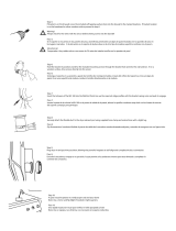
Please read through these instructions completely to be sure you’re comfortable with this easy install process.
Also check your TV owner’s manual to see if there are any special requirements for mounting your TV.
If you do not understand these instructions or have doubts about the safety of the installation, assembly
or use of this product, contact Customer Service.
Do you have all of
the tools needed?
3
4
CAUTION: Avoid potential personal injuries and property damage!
● This product includes directions and hardware for use with wood studs, solid concrete and concrete block
walls,
and drywall only.
● The wall must be capable of supporting five times the weight of the TV and mount combined.
● Do not use this product for any purpose not explicitly specified by manufacturer.
● Manufacturer is not responsible for damage or injury caused by incorrect assembly or use.
Ready to begin?
Included
Included
1/8 in. (3.2 mm)
Wood
5/16 in. (8 mm)
Masonry
Screwdriver
Tape
Measure
Stud Finder
Hammer
Hammer
Awl
Pencil
Drill Bit
Drill Bit
Electric
Drill
Electric
Drill
Square Driver Bit
Square Driver Bit
Drywall
Applications
NO DRILL OPTION
Wood Stud
Applications
Concrete
Applications

4
Parts and Hardware [for STEP 1]
Parts and Hardware
WARNING: This product contains small items that could be a choking hazard if swallowed. Before starting assembly, verify all parts are included and
undamaged. If any parts are missing or damaged, do not return the damaged item to your dealer; contact Customer Service. Never use damaged parts!
NOTE: Not all hardware included will be used.
01
03
02
04
M8 x 50mm
M8 x 25mm
M8 x 35mm
M8 x 16mm
M6 x 12mm
M6 x 20mm
M6 x 35mm
TV Screws (qty. 2 each)
[Only one size fits your TV]
Washer
Spacers
[If necessary]
TV Bracket
qty.1
qty.2
qty.4
M6
2.5mm
M8/M6
M8
qty.2
22mm

5
#10 x 2 ½ in.
Fischer UX8 x 50R
14 ga. x 1 ¼ in.
For CONCRETE installations ONLY For DRYWALL installations ONLY
Parts and Hardware [for STEP 2]
Parts [for STEP 3] (OPTIONAL)
Tools Included
*
WARNING: This product contains
a magnet. If an implanted medical device
such as a pacemaker or implantable
cardioverter defibrillator (ICD) is in use,
magnetic fields may aect the operation
of those devices, resulting in serious injury
or death. If you have an implanted medical
device, keep at least 13 cm (5 in.) between
your device and the magnet. Please
consult with your physician or medical
professional prior to using this product.
C1
Wall Plate
Concrete Anchor
Nail
Washer
(Wood Screw)
Stando
*
(Magnetic Leveling Foot)
Disc
(Adhesive backed)
Wood Screw (Wall Plate)
FOR STEP 2B and STEP 2C ONLY
Driver Bit
(Square)
CAUTION: FOR STEP 2C ONLY:
Do not use in drywall or wood.
CAUTION: FOR STEP 2A ONLY:
Do not use in concrete or plaster & lath.
Built-in Level
NOTE: These anchors are NOT INCLUDED.
Contact Customer Service for anchor kit #CMK3.
05
qty.1
06
qty.2
07
qty.2
08
qty.32
09
qty.2
10
qty.2
11
qty.1
qty.2
Locking Mechanism
KEEP IN THE LOCKED POSITION
until instructed.
UNLOCKED
LOCKED

6
1
1 .1 Select TV Screw Diameter 1.2 Determine TV Screw Length
NOTE: Only one screw size fits your TV.
• Flat Back TV • Rounded Back TV
• Extra Space Needed
[for cables or inset holes]
A
Too Short
Too Long
CAUTION:
Verify adequate thread
engagement with your screw/
washer/spacer combination
AND TV Bracket
04
.
- Too short will not hold the TV.
- Too long will damage the TV.
Correct
B
spacers
03
are not
necessary.
Rounded
Back
Flat Back
Cable
Interference
Inset
Holes
Use spacers
03
to create extra space
between the TV and TV bracket.
03
03
Attach TV Bracket to TV
M6
M8
04
04

7
Attach TV Bracket to TV
1.3 Attach the TV Bracket
03
01
02
02
01
• Flat Back TV
A
B
• Rounded Back TV
• Extra Space Needed
Top of TV
Spacer Options
04
If your TV included inset
spacers or wall mount adapters,
use them
UNDER the
mount hardware.

8
2
IMPORTANT:
You must determine
your wall construction to
correctly secure the wall
plate to the wall.
Attach Wall Plate to Wall
STEP 2A
on PAGE 10
DRYWALL
[TVs up to 100 lbs. (45.3 kg)]
CAUTION: Avoid potential personal injuries and
property damage!
Wood stud(s) are okay
to nail through
CAUTION:
DO NOT install into plaster & lath walls
Follow the corresponding
step for your installation
method.
● DO NOT mount to patched areas/drywall seams /uneven walls
● Drywall must be of sound construction with no water damage
If water damage ever occurs - remove the TV immediately
● Your TV MUST be centered on the wall plate
05

9
STEP 2B
on PAGE 12
WOOD STUD
[TVs up to 135 lbs. (61.2 kg)]
Two stud centers must be located for proper
installation.
CAUTION: Avoid potential personal injuries and
property damage!
Attach Wall Plate to Wall
STEP 2C
on PAGE 14
SOLID CONCRETE
and
CONCRETE BLOCK
[TVs up to 135 lbs. (61.2 kg)]
CAUTION: Avoid potential personal injuries and
property damage!
The mount must be installed directly onto the
concrete surface (no surface covering).
05 05

10
2A
CAUTION: Avoid potential
personal injuries and property damage!
●Drywall covering must be 3/8 in.
(9.5 mm) or greater
●Drywall must be mounted on studs, no
more than 24 in. (609 mm) on center,
[minimum stud size: nominal 2 x 4 in. (51 x
102 mm) actual 1½ x 3½ in. (38 x 89 mm)]
●Drywall must be sound with no water
damage. If water damage ever occurs
— remove the TV immediately
●DO NOT mount to patched areas,
on drywall seams or uneven walls
CAUTION: Avoid potential personal injuries and property damage!
If ANY of the 32 nails
08
encounter excessive resistance (metal object) - STOP and call
customer service. DO NOT reuse nails
08
after removing, or use store-bought nails.
2A.1 Verify Your Wall 2A. 2 Attach the Wall Plate
DRYWALL (only) INSTALLATION [TVs up to 100 lbs. (45.3 kg)]
Min.
3/8 in. (9.5 mm)
1 2
OUTER HOLE
OUTER HOLE
08
08
Position wall plate
05
on your wall, and secure a nail
08
in BOTH OUTER holes.
IMPORTANT: Wall plate
05
MUST be level when securing the second nail
08
.
● DO NOT install into plaster & lath walls
05
05
05

11
IMPORTANT: Alternate installing the remaining thirty (30) nails
08
from side to side.
CAUTION: Avoid potential personal injuries and property damage! Thirty-two (32)
nails
08
total, must be used in wall plate
05
.
Go to STEP 3 on PAGE 16.
3
(qty. 30)
08
05

12
2B
CAUTION: Avoid potential personal injuries
and property damage!
● Drywall covering the wall must not exceed
5/8 in. (16 mm)
● Minimum wood stud size: nominal 2 x 4 in.
(51 x 102 mm) actual 1½ x 3 ½ in. (38 x 89 mm)
● Minimum horizontal space between fasteners:
16 in. (406 mm)
● Stud centers must be verified – not all walls
have conventional 16 in. (406 mm) stud spacing
2 B.1 Verify Your Wall
WOOD STUD INSTALLATION [TVs up to 135 lbs. (61.2 kg)]
1
Max.
5/8 in.
(16 mm)
Min.
16 in.
(406 mm)
Min. 1
½
in. (38 mm)
Min. 3
½
in. (89 mm)
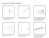
2B.2 Attach the Wall Plate
2
Locate the center of BOTH
studs using a stud finder,
an awl or small nail.
Position wall plate
05
over your
studs and mark the hole positions.
IMPORTANT: If you DO NOT have two studs that are 16 inches (406 mm)
apart – OR – you cannot center wall plate
05
on your studs, follow STEP
2B on PAGE 12, for drywall installation.
05

13
3 4
CAUTION: Improper use could reduce the holding power
of screws
07
. DO NOT over-tighten the screws.
Go to STEP 3 on PAGE 16.
0711
05
06
IMPORTANT: Holes must be drilled to a depth
of 2 ½ in. (63 mm) — in the center of the stud.
Drill 1/8 in. (3.2 mm) pilot holes.
Install wall plate
05
with screws
07
and washers
06
.
2 ½ in. (63 mm)
1/8 in.
(3.2 mm)

14
2C
2C.1 Verify Your Wall
SOLID CONCRETE / CONCRETE BLOCK INSTALLATION [TVs up to 135 lbs. (61.2 kg)]
CAUTION: Avoid potential personal injuries and property damage!
●Minimum solid concrete thickness: 8 in. (203 mm)
●Minimum concrete block size: 8 x 8 x 16 in. (203 x 203 x 406 mm)
●Minimum horizontal space between fasteners: 16 in. (406 mm)
●Mount wall plate
05
directly onto the concrete surface (no wall covering)
2C.2 Attach the Wall Plate
1
Min. 16 in.
(406 mm)
Min.
8 in.
(203 mm)
Min. 16 in.
(406 mm)
Min.
8 in.
(203 mm)
Position wall plate
05
on your wall.
Concrete Installation Kit is required [NOT INCLUDED]
Contact Customer Service 1-855-734-7805 for kit
#CMK3
.
Solid Wall Block Wall
05

15
SOLID CONCRETE / CONCRETE BLOCK INSTALLATION [TVs up to 135 lbs. (61.2 kg)]
IMPORTANT: Holes must be
drilled to a depth of 2¾ in. (70 mm).
Never drill into the mortar between blocks.
CAUTION: Be sure the anchors
C1
are seated flush with the
concrete surface.
CAUTION: Improper use could
reduce the holding power of screws
07
.
DO NOT over-tighten the screws.
002862.eps
5/16 in.
(8 mm)
2¾ in. (70 mm)
11 07
2 3 4
06
Drill 5/16 in. (8 mm) pilot holes.
Install wall plate
05
with screws
07
and washers
06
.
Insert anchors
C1
(Fischer UX8 x 50R –
included in the Concrete Installation Kit)
C1
05

16
3
3 .1 Unlock the Wall Plate 3.2 Hang Your TV
HEAVY! You may need assistance with this step.
Side View
Attach TV to Wall Plate
IMPORTANT: DO NOT lower TV straight down onto
wall plate
05
-- this will engage the lock. Safety latch must
be released for proper installation (See STEP 3.1).
05
05
04
04
05

17
Side View
Attach TV to Wall Plate
3.3 Lock the Wall Plate
CAUTION: Avoid potential personal injury or property damage!
The locking mechanism must be locked, so the TV is securely
fastened to the wall plate
05
.
Side View Side View
Button
04
05
05

18
3.4 No Tilt Feature (OPTIONAL)
A
B
For non-metal
back TVs, use
adhesive disc
10
.
For non-metal
back TVs, use
adhesive disc
10
.
03
03
09 09
09
09
09
09
09
10
10
09
09
09
10
10

19
Manage Cables Adjustments
SIDE-TO-SIDE SHIFT
Slide the TV side to side to adjust positioning.
NOTE: Safety stops prevent over-shifting.
Make sure your TV is locked to wall plate
05
(STEP 3.3).
CAUTION: Avoid potential personal
injury or property damage!
DO NOT force open your TV when adding cables. STOP
lifting the bottom outward when you feel resistance.
CAUTION: Avoid potential personal
injury or property damage!
FOR DRYWALL INSTALLATIONS: DO NOT slide the
TV side-to-side.
05

20
REMOVE THE TV
1. Disconnect your cables.
2. Unlock wall plate
05
(STEP 3.1).
3. Lift the TV up and away from wall plate
05
.
CAUTION: Avoid potential personal injuries
and property damage!
DO NOT reuse this product after removing wall
plate
05
from the wall.
LEVEL [Wood Stud and Concrete Installations]
1. Remove the TV.
2. Loosen both screws
07
.
3. Adjust the level.
4. Retighten both screws
07
.
Loosen
Loosen
Tighten
Tighten
07
HEAVY! You may need assistance with this step.
Adjustments
05
/