Page is loading ...

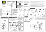
Recommended placement
Our US-based
install experts
are standing
by to help.
Call us at:
1-855-734-7805
Get it right the
first time.
HeightFinder
™
shows you
where to drill.
Check it out at:
SANUS.com/2850
Want to watch a
video that shows
how easy this DIY
project will be?
Watch it now at:
SANUS.com/2849
WE’RE HERE TO HELP
LLF
122
INSTRUCTION MANUAL
Para Español ver página 20

2
CAUTION: Avoid potential personal injuries and property damage!
● This product is designed ONLY to be installed into wood studs, solid concrete or concrete block.
— DO NOT INSTALL INTO DRYWALL ALONE — DRYWALL ALONE WILL NOT HOLD THE WEIGHT OF YOUR TV.
● This product is designed for INDOOR USE ONLY.
● The wall must be capable of supporting five times the weight of the TV and mount combined.
● Do not use this product for any purpose not explicitly specified by manufacturer.
● Manufacturer is not responsible for damage or injury caused by incorrect assembly or use.
125 lbs.
(56.6 kg)
Please read through these instructions completely to be sure you’re comfortable with this easy install process.
Check your TV owner’s manual to see if there are any special requirements for mounting your TV.
If you do not understand these instructions or have doubts about the safety of the installation, assembly or use of this product,
contact Customer Service: 1-855-734-7805.
TV Weight Limit
(including accessories)
DO NOT EXCEED
If your TV (plus accessories) weighs MORE, this mount is NOT compatible.
Visit MountFinder.Sanus.com or call customer service to find a compatible mount.
CAUTION:
DO NOT exceed the
maximum weight indicated. This mounting
system is intended for use only with the
maximum weights indicated. Use with
products heavier than the maximum weights
indicated may result in collapse of the mount
and its accessories, causing possible injury.
CAUTION: IMPORTANT SAFETY INSTRUCTIONS
PLEASE READ ENTIRE MANUAL PRIOR TO USE — SAVE THESE INSTRUCTIONS

3
Call Customer Service: 1-855-734-7805
Tools Needed
Wall
Construction
ONLY install on
these acceptable
wall types.
Drywall alone
will
NOT hold the
weight of your TV
Unsure
wood studs Solid concrete or
concrete block
ACCEPTABLE
Concrete kit CMK1 is required
[NOT INCLUDED] Call Customer Service
Wood Stud Install
Concrete Install
Awl
Pencil Level Tape
Stud
Finder
ScrewdriverTape
Measure
7/32 in.
(5.5 mm)
Wood
Drill Bit
Electric
Drill
Hammer
1/2 in.
(13 mm)
Socket
Wrench
Drill Bit
3/8 in.
(10 mm)
Concrete
CAUTION:
DO NOT
install in
drywall
alone
ACCEPTABLE

4
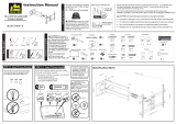
0.35in
9mm
15.98in
406mm
0.87in
22mm
9.00in
228.5mm
7.62in
193.5mm
5.31in
135mm
5.31in
135mm
25.91in
658mm
17.13in
435mm
35deg
35deg
2.53in
64.2mm
9.24in
234.6mm
7.89in
200.4mm
22.00in
558.8mm
15deg
DOWN
8deg TILT
SIMULATED 70"
FLAT SCREEN TV
WALL PLATE
TOP VIEW - SWIVEL
3-D
SIDE VIEW - EXTENSION/TILT
SIDE VIEW - RETRACTED
FRONT VIEW - TILT
FULLY ASSEMBLED MOUNT
WALL IS ON RIGHT
WALL IS ON RIGHT
WALL IS ON TOP
WALL IS ON TOP
15.75in
400mm
MAX
23.62in
600mm
MAX
7.87in
200mm
MIN
TV INTERFACE
MIN
200mm
7.87in
Dimensions

5
5/16 in.
5/16 x 2¾ in.
M5 x 8mm
M6/M8
2.5mm
22mm
M8 x 25mm M8 x 50mm
M6 x 12mm
M8 x 16mm
M6 x 35mmM6 x 20mm
M8 x 35mm
Supplied Parts and Hardware
WARNING: This product contains small items that could be a choking hazard if swallowed.
Before starting assembly, verify all parts are included and undamaged. If any parts are missing or damaged, do not return
the damaged item to your dealer; contact Customer Service. Never use damaged parts!
NOTE: Not all hardware included will be used.
STEP 1 Parts and Hardware
TV Screws
(qty. 4 each)
[Only one size fits your TV]
M6
M8
Washer
(qty. 4 each)
Spacers
[If necessary]
03
02
01
Vertical TV Bracket
Horizontal TV Bracket
Wing Nuts
M5
05
04
qty. 8
qty. 1
qty. 2
06
qty. 4
qty. 4
Shipped Attached

6
5/16 in.
5/16 x 2¾ in.
M5 x 8mm
M6/M8
2.5mm
22mm
M8 x 25mm M8 x 50mm
M6 x 12mm
M8 x 16mm
M6 x 35mmM6 x 20mm
M8 x 35mm
Wall Plate Assembly
Wall Plate Template
Securement Screw
Washer [Securement Screw]
Hex Key
Cable Tie
11
12
13
14
Lag Screw
09
07
08
10
Washer [Lag Screw]
STEP 2 Parts and Hardware
STEP 3 Hardware
Installation / Adjustments
qty. 1
qty. 1
qty. 1
qty. 1
M4
qty. 4
qty. 4
qty. 4
qty. 1

7
5/16 x 2¾ in.
5/16 in.
Fischer UX10 x 60R
Concrete Anchors
For concrete installations ONLY
CAUTION: Do not use in drywall or wood
1/4-20 x 1.75
1/4 in.
5/16 x 2¾ in.
5/16 in.
Fischer UX10 x 60R
Concrete Anchors
For concrete installations ONLY
CAUTION
: Do not use in drywall or wood
1/4-20 x 1.75
1/4 in.
5/16 x 2¾ in.
5/16 in.
Fischer UX10 x 60R
Concrete Anchors
For concrete installations ONLY
CAUTION: Do not use in drywall or wood
1/4-20 x 1.75
1/4 in.
Lag Bolt
Washer
C2
C3
C1
Hardware for STEP 2B
Concrete Installation [Concrete Kit CMK1 is NOT INCLUDED]
Contact Customer Service to inquire about the Concrete Installation Kit CMK1.
qty. 4
qty. 4
qty. 4

8
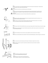
STEP 1 Attach TV Bracket to TV
1-1 Select TV Screw
Diameter
1-2 Select TV Screw Length
Too Short
Too Long
CAUTION:
Verify adequate thread
engagement with the screw or
screw/spacer combination.
- Too short will not hold the TV.
- Too long will damage the TV.
Correct
M6
M8
a
b
a
: For flat-back TVs,
no spacers
03
required.
b
: Spacers
03
supplied for:
● Round (irregular) back TVs
● Extra space needed (for cables
or inset mounting holes)
FLAT BACK ROUND BACK CABLES INSET HOLES
03
If your TV included inset
spacers or wall mount adapters,
use them
UNDER the
mount hardware.
Hand thread screws into the
threaded inserts on the back of
your TV to determine which screw
diameter (M6, or M8) to use.

9
1-3 Attach TV Bracket
Measure the HEIGHT (H) of your TV's
mounting hole pattern.
inch dimensions are approximate
inches cm mm
7 ⅞ 20 200
11 ¾ 30 300
15 ¾ 40 400
23 ¾ 60 600
1 2 3
H
H
mm
NOTE: Position the slotted holes as
shown for your TV hole pattern Height (H).
HEIGHT (H) equal (=) 200 mm
HEIGHT (H) greater than (>) 200 mm

10
Center the TV brackets
04
and
05
over the
hole pattern on your TV.
NOTE: If the TV brackets are not centered,
you may need to reposition to align properly (see
previous step).
4
05
04
05
Slide horizontal TV brackets
05
onto the vertical TV bracket
04
as shown.
Angle the brackets
05
to clear the
screw posts.
Tilt the brackets
05
to
nest the screw posts.
Screw
posts
04
5
05
TV HOLE
PATTERN
TOP OF TV
05
04
For HEIGHT (H) equal (=) 200 mm
Screw posts on horizontal TV bracket
05
must sit
in bottom hole of vertical TV bracket
04
.

11
a: Flat Back
b: Round Back / Extra Space
Secure the assembly with the four
wing nuts
06
.
06
6
03
02
02
01
01
7
Center the TV bracket assembly
over your TV's hole pattern and attach using
screw combination
a
or
b
you selected for your TV.
CAUTION: Avoid potential personal injuries and property damage! DO NOT
use power tools for this step. Tighten the screws
01
only enough to secure the
TV brackets to the TV.
05
06
05
04

12
Locate studs. Verify the center of the stud(s) using an awl, a thin nail,
or an edge to edge stud finder.
1
2
MIN.
16 in.
(406 mm)
Level the wall plate template
07
and align the hole pattern over
the center of your studs, then tape in place.
STEP 2A Attach Wall Plate Wood Stud
Installation
MAX 5/8 in. (16 mm)
CAUTION: Avoid potential personal injury or property damage!
● Drywall covering the wall must not exceed 5/8 in. (16 mm)
● Minimum wood stud size: nominal 2 x 4 in. (51 x 102 mm) actual 1 ½ x 3 ½ in. (38 x 89 mm)
● Minimum horizontal space between fasteners: 16 in. (406 mm)
● Stud centers must be verified
07

13
09
3 4
10
Drill pilot holes then remove the wall plate template
07
.
IMPORTANT: Be sure to drill into the center of the stud.
IMPORTANT: Pilot holes must be drilled to a depth of 2 ¾ in. (70 mm),
using a 7/32 in. (5.5 mm) diameter drill bit.
Install the wall plate
08
using four lag bolts
09
and washers
10
.
Tighten all lag bolts only until they are pulled firmly against the wall plate.
CAUTION: Improper use could reduce the holding power of the
lag bolt. DO NOT over-tighten the lag bolts.
Go to STEP 3 on PAGE 16.
07
08
7/32 in.
(5.5 mm)
2¾
in. (70 mm)

14
Concrete Install Kit #CMK1 is not included
(see page 7) Contact Customer Service
at 1-855-734-7805 to inquire about the
Concrete Installation Kit CMK1.
CAUTION: Avoid potential personal injury or property damage!
● Mount the wall plate assembly
08
directly onto the concrete surface
● Minimum solid concrete thickness: 8 in. (203 mm)
● Minimum concrete block size: 8 x 8 x 16 in. (203 x 203 x 406 mm)
● Minimum horizontal space between fasteners: 16 in. (406 mm)
1 2
Level the wall plate template
07
and tape in place.
Drill four pilot holes.
CAUTION: Never drill into the mortar between blocks.
IMPORTANT: Pilot holes must be drilled to a depth of 3 in.
(75 mm), using a 3/8 in. (10 mm) diameter drill bit.
MIN.
16 in.
(406 mm)
002862.eps
STEP 2B Attach Wall Plate
Solid Concrete or Concrete Block Installation
07
07
3/8 in.
(10 mm)
3 in. (75 mm)

15
3
4
Remove wall plate template
07
and insert four concrete
anchors
C1
.
CAUTION: Be sure the anchors are seated flush with
the concrete surface.
Install the wall plate
08
using four lag bolts
C3
and
washers
C2
. Tighten all lag bolts only until they are pulled
firmly against the wall plate.
CAUTION: Improper use could reduce the holding
power of the lag bolt. DO NOT over-tighten the lag bolts.
08
C1
C3
C2

16
HEAVY! You may need assistance with this step.
STEP 3 Hang TV onto Wall Plate
Lock TV to wall plate assembly
08
with screw
11
and washer
12
.
CAUTION! Avoid potential personal injuries and property
damage!Screw
11
must be installed to secure your TV onto
the wall plate assembly
08
.
Hang your TV onto the arm of wall plate assembly
08
by
first hooking the top support, then resting the TV into place.
1 2
08
04
11
12

17
Manage Cables
Fully extend the arms before routing cables.
Use cable ties
14
to bundle and attach
cables to the arms
08
for a cleaner look.
08
14

18
TV Adjustments
TILT LEVEL
1. Loosen the tilt lever
T
.
2. Adjust the TV tilt position.
3. Tighten tilt lever
T
to secure the TV in place at your desired tilt angle.
NOTE: If needed, tighten screw
T2
for additional tilt tensioning.
T2
T
Tighten
Tighten
Loosen
Loosen
1. Loosen the screw
11
on the rear of wall
plate assembly
08
.
2. Level your TV.
3. Retighten screw
11
to secure in place.
Tighten
Loosen
13
08
08
11

19
REMOVING THE TV
To remove your TV from the wall plate assembly
08
:
1. Disconnect all cables.
2. Remove screw
11
and washer
12
.
3. Lift the TV up and off of wall plate assembly
08
.
HEAVY! You may need
assistance with this step.
3
2
1
08
11
12

20
Llame al Servicio
de Atención al
Cliente
herramientas
necesarias
La construcción
de su pared
SOLAMENTE instalar
en estos tipos
aceptables de la pared.
Instalación en panels de
yeso solo NO soportará
el peso de su TV.
¿No está
seguro?
Montantes de
madera
Hormigón macizo o
bloque de hormigón
ACEPTABLE
Se requiere el kit CMK1
para montantes de
Cemento
(no incluido)
Montantes de
Madera
Montantes de
Cemento
Punzón
Lápiz Nivel Cinta
Adhesiva
Localizador
de
montantes
Destornillador
Cinta
métrica
5,5 mm
(7/32'')
Madera
Broca
Taladro
eléctrico
Martillo
13 mm
(1/2 in.)
Llave de
vaso
Broca
10 mm
(3/8'')
Hormigón
PRECAUCIÓN:
NO instalar
en panel de
yeso solo
56,6 kg
(125 lbs.)
Lea atentamente estas instrucciones en su totalidad para asegurarse de que está familiarizado con el sencillo proceso de instalación.
Consulte igualmente el manual de su televisor para conocer si existen requisitos especiales para el montaje de su aparato.
Si no entiende las instrucciones o si tiene dudas acerca de la seguridad de la instalación, el montaje o el uso del producto, póngase en contacto con el Servicio
de Atención al Cliente o llame a nuestro servicio técnico al número 1-855-734-7805 .
PRECAUCIÓN: Evite posibles lesiones personales y daños materiales.
● Este producto se ha diseñado para su uso en montantes de madera, hormigón macizo y paredes de bloques de hormigón: NO lo instale en paredes
únicamente de yeso
● Este producto está diseñado para uso en interiores solamente.
● La pared debe ser capaz de soportar hasta cinco veces el peso combinado del televisor y la montura
● No utilice este producto para ningún otro propósito que no sea el explícitamente especificado por el fabricante
● El fabricante no se responsabiliza de ningún daño o lesión resultante del montaje incorrecto o el uso indebido
Peso máximo
(incluidos los accesorios)
NO EXCEDAS
Si su TV (incluidos los accesorios) pesa MÁS, esta montura NO es
compatible.
Visite sanus.com o llame al número 1-855-734-7805 para encontrar una
montura compatible.
ACEPTABLE
INSTRUCCIONES IMPORTANTES DE SEGURIDAD
- LEA TODO ESTE MANUAL ANTES DE UTILIZAR ESTE PRODUCTO - GUARDE ESTAS INSTRUCCIONES
ESPAÑOL
/