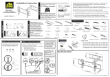
Sanus LLT1 Installation guide

Type
Installation guide

This manual is also suitable for

Sanus LLT1 is an innovative TV wall mount designed to make your TV viewing experience more enjoyable. This full-motion mount allows you to extend, tilt, and swivel your TV for optimal viewing angles from anywhere in the room. It features a sturdy construction that can support TVs weighing up to 125 lbs, making it ideal for most flat-panel TVs. The LLT1 also includes a built-in level and a HeightFinder™ tool to ensure precise and easy installation.

Sanus LLT1 is an innovative TV wall mount designed to make your TV viewing experience more enjoyable. This full-motion mount allows you to extend, tilt, and swivel your TV for optimal viewing angles from anywhere in the room. It features a sturdy construction that can support TVs weighing up to 125 lbs, making it ideal for most flat-panel TVs. The LLT1 also includes a built-in level and a HeightFinder™ tool to ensure precise and easy installation.

Para Español ver página 24
LLT1
INSTRUCTION MANUAL
Recommended placement
Our US-based
install experts
are standing
by to help.
Call us at:
1-855-734-7805
Get it right the
first time.
HeightFinder
shows you
where to drill.
Check it out at:
SANUS.com/2850
Want to watch a
video that shows
how easy this DIY
project will be?
Watch it now at:
SANUS.com/2846
WE’RE HERE TO HELP
125 lb
(56.6 kg)
110 lb
(49.8 kg)
For walls with:
wood studs, solid concrete,
and concrete block walls
For walls with:
steel studs
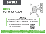
IMPORTANT SAFETY INSTRUCTIONS – PLEASE READ MANUAL PRIOR TO USE – SAVE THESE INSTRUCTIONS
Please read through these instructions completely to be sure you’re comfortable with this easy install process.
Check your TV owner’s manual to see if there are any special requirements for mounting your TV.
If you do not understand these instructions or have doubts about the safety of the installation, assembly or use of this product,
contact Customer Service 1-855-734-7805.
CAUTION: Avoid potential personal injuries and property damage!
This product is designed ONLY to be installed into wood studs, solid concrete or concrete block. For information on how to use this product
with steel stud walls contact Customer Service and ask about the steel stud mounting kit
DO NOT INSTALL INTO DRYWALL ALONE — DRYWALL ALONE WILL NOT HOLD THE WEIGHT OF YOUR TV.
This product is designed for INDOOR USE ONLY.
The wall must be capable of supporting five times the weight of the TV and mount combined.
Do not use this product for any purpose not explicitly specified by manufacturer.
Manufacturer is not responsible for damage or injury caused by incorrect assembly or use.
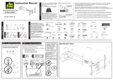
TV Weight Limit
(including accessories)
DO NOT EXCEED
If your TV, plus accessories
weighs MORE than indicated,
this mount is NOT compatible.
Visit SANUS.com or call
customer service to find a
compatible mount.
1-855-734-7805
2
Call Customer Service
1-855-734-7805
Tools Needed
Wall
Construction
ONLY install on
these acceptable
wall types.
Drywall
alone will
NOT hold
the weight
of your TV.
Unsure
wood studs Steel studsSolid concrete or
concrete block
ACCEPTABLE
Steel Stud Kit #SSMK1
required (not included)
Call Customer Service to
inquire about the kit.
ACCEPTABLE
Wood Stud Install
Steel Stud Install
Concrete Install
Awl Awl
Pencil Level Tape
Stud
Finder
Stud
Finder
ScrewdriverTape
Measure
7/32 in.
(5.5 mm)
Wood
1/2 in.
(13 mm)
Steel
Drill Bit Drill Bit
Electric
Drill
Hammer
1/2 in.
(13 mm)
Socket
Wrench
Drill Bit
3/8 in.
(10 mm)
Concrete
CAUTION:
DO NOT install
in drywall alone
3
4
Dimensions in. [mm]
3.94in
100mm
MIN
23.62in
600mm
MAX
15.75in
400mm
MAX
3.94in
100mm
MIN
27.00in
685.9mm
7.10in
180.4mm
17.69in
449.2mm
2.83in
71.8mm
0.33in
8.4mm
16.00in
406.4mm
24.00in
609.6mm
30.91in
785mm
17.72in
450mm
4.95in
125.7mm
7.73in
196.2mm
1.00in
[25.4mm]
TOTAL HEIGHT
ADJUSTMENT
2.30in
58.3mm
5.75in
146.1mm
3.94in
100mm
KNOBS
KNOBS ARE TO ONLY FACE TO THE
INSIDE ONLY IF A 100 X 100 VESA
PATTERN IS REQUIRED FOR INSTALLATION
12deg
5deg
TV INTERFACE
WALL PLATE
TOP VIEW
3-D
100 X 100 VESA PATTERN ORIENTATION
SIDE VIEW
HEIGHT ADJUST
FULLY ASSEMBLED MOUNT
Parts and Hardware for STEP 2
5
NOTE: Not all hardware included will be used.
WARNING: This product contains small items that could be a choking hazard if swallowed.
Before starting assembly, verify all parts are included and undamaged. If any parts are missing or damaged, do not return the damaged item to
your dealer; contact Customer Service. Never use damaged parts!
Supplied Parts and Hardware
5/16 x in.
5/16 in.
Fischer UX10 x 60R
M5 x 25mm
M8 x 25mm M8 x 50mm
M6 x 12mm
M8 x 16mm
M6 x 35mmM6 x 20mm
M8 x 35mm
TV Brackets
TV Screws
(qty. 4 each)
[Only one size fits your TV]
Washer Spacers
[If necessary]
03
02
01
M6/M8
M6/M8
2.5 mm
M6/M8
22 mm
M6
M8
(qty. 1)
04
(qty. 1)
05
(qty. 4)
(qty. 4)
(qty. 8)
M4 M6 / M8
5/16 x 2¾ in.
5/16 in.
Fischer UX10 x 60R
M4
M5 x 25mm
2.5mm
22mm
M8 x 50mm
M6 x 20mm
M6 x 12mm
M8 x 16mm M8 x 25mm
M8 x 20mm
M4 x 12mm
M6 x 35mm
M8 x 35mm
M4 x 35mm
M8 x 45mm
Parts and Hardware for STEP 2
Concrete Anchor
For concrete installations ONLY
CAUTION: Do not use in drywall or wood
Fischer UX10 x 60R
6
(qty. 1)
06
(qty. 1)
07
(qty. 4)
08
(qty. 4)
09
(qty. 4)
10
Wall Plate Template
Wall Plate
Lag Bolt
Lag Bolt Washer
Hardware for STEP 2C (not included)
Steel Stud Anchor Kit #SSMK1 (not included)
Contact Customer Service to inquire about the additional hardware.
M4 M6 / M8
5/16 x 2¾ in.
5/16 in.
Fischer UX10 x 60R
M4
M5 x 25mm
2.5mm
22mm
M8 x 50mm
M6 x 20mm
M6 x 12mm
M8 x 16mm M8 x 25mm
M8 x 20mm
M4 x 12mm
M6 x 35mm
M8 x 35mm
M4 x 35mm
M8 x 45mm
Hardware for STEP 3
7
1/4-20 x 1¾ in.
1/4 in.
1/4-20 Snap Toggle BB
(qty. 4)
(qty. 4)
(qty. 4)
(qty. 1)
11
(qty. 2)
12
S1
S2
S3
Hex Key
Securement Screw
STEP 1 Attach Brackets to TV
Inset Holes Cables Rounded Back
1.2 Select TV Screw Length and Spacers
Flat Back TV
[TV brackets
04
/
05
lay flat on your TV]
NO SPACER SPACER NEEDED
Flat Back TV with
Extra Space Needed
[for deep inset holes
or cable interference]
Rounded or
Irregular Back TV
[TV brackets
04
/
05
NOT resting flat on your TV]
A B
Use short TV screws
01
.
Spacers
03
not needed.
Use long TV screws
01
and spacers
03
to
create extra space between the TV and TV bracket.
CAUTION: Verify adequate thread engagement with your
screw
01
, washer
02
, spacer
03
combination AND TV brackets
04
/
05
.
Too short will not hold your TV. Too long will damage your TV.
Too Short
Too Long
Correct
1.1 Select TV Screw Diameter
Only one screw size fits your TV.
M6
M8
01
8
Center the TV brackets
04
and
05
over your TV hole pattern - making sure the brackets are level.
IMPORTANT: The tilt tension knob
T
on TV brackets
04
and
05
should normally be oriented to the outside edges, EXCEPT for
TVs with 100 mm (4 in. wide) mounting hole spacing - these TVs require switching the TV brackets
04
and
05
.
Install using the spacer, TV screw and washer combination
A
or
B
you selected for your TV.
CAUTION: Avoid potential personal injuries and property damage! DO NOT use power tools for this step. Tighten the screws only enough to
secure the TV bracket to the TV. DO NOT overtighten the screws.
1.3 Attach Brackets to TV
NO SPACER
SPACER NEEDED
A
B
05
04
02
02
01
01
ONLY for 100 mm (4 in.)
TV mounting hole spacing,
switch the TV brackets
04
and
05
on your TV.
100 mm (4 in.)
04
05
T
03
9
If your TV included
inset spacers or wall mount
adapters, use them
UNDER the
mount hardware.
T
T
10
1
2
≤16 mm
(5/8 in.)
406-610 mm
(16-24 in.)
06
STEP 2A Attach Wall Plate Wood Stud Installation
CAUTION: Avoid potential personal injury or property damage!
Drywall covering the wall must not exceed 16 mm (5/8 in.)
Minimum wood stud size: nominal 51 x 102 mm (2 x 4 in.) actual 38 x 89 mm (1 ½ x 3 ½ in.)
Minimum horizontal space between fasteners: 406 mm (16 in.)
Stud centers must be verified
NOTE: TV with brackets can be shifted to the left or right from
center. Consider this when selecting the location of your wall mount.
11
3 4
3 in. (75 mm)
7/32 in.
(5.5 mm)
Install the wall plate
07
using four lag bolts
08
and washers
09
.
Tighten all lag bolts only until they are pulled firmly against the wall plate.
CAUTION: Improper use could reduce the holding power of the
lag bolt. DO NOT over-tighten the lag bolts.
Go to STEP 3 on PAGE 19.
06
08
09
07
12
1 2
3/8 in.
(10 mm)
3 in. (75 mm)
CAUTION: Avoid potential personal injury or property damage!
Mount the wall plate
07
directly onto the concrete surface
Minimum solid concrete thickness: 8 in. (203 mm)
Minimum concrete block size: 8 x 8 x 16 in. (203 x 203 x 406 mm)
Minimum horizontal space between fasteners: 24 in. (610 mm)
STEP 2B Attach Wall Plate
Solid Concrete or Concrete Block Installation
002862.eps
24 in.
(610 mm)
06
06
NOTE: TV with brackets can be shifted to the left or right from
center. Consider this when selecting the location of your wall mount.
13
3 4
Install the wall plate
07
using four lag bolts
08
and washers
09
.
Tighten all lag bolts only until they are pulled firmly against the wall plate.
CAUTION: Improper use could reduce the holding power of the
lag bolt. DO NOT over-tighten the lag bolts.
Go to STEP 3 on PAGE 19.
09
08
10
07
CAUTION: Avoid potential personal injuries and property damage!
Studs must be at least 2x4 in. / 25 ga.
If back side of wall is unfinished, drywall must be installed to a minimum of one stud left and right of the stud(s) being used to install the mount
Drywall must be a minimum of 1/2 in. (13 mm) thick on each side of the studs, and a minimum clearance of 1 in. (48 mm) behind the wall is required
Pilot holes MUST be drilled to a depth of 1 in. (26 mm), using a 1/2 in. (13 mm.) diameter drill bit
This product must be centered on the studs
Stud type and structural strength must conform to the North American Specification for the Design of Cold-Formed Steel Structural
Members [362 S 125 18, C-Shape, S - Stud Section]
Drywall must be secured to studs with screws 12 in. (304.8 mm) on center
STEP 2C Attach Wall Plate
Steel Stud Installation
Steel Stud Anchor Kit (not included) -
Contact Customer Service at 1-855-734-7805 to inquire about the additional hardware.
14
1/4-20 x 1¾ in.
1/4 in.
1/4-20 Snap Toggle BB
S1 x4
S2 x4
S3 x4
24 in.
(609 mm)
16 in.
(406 mm)
24 in.
(609 mm)
16 in.
(406 mm)
21
16 in. (406 mm)
24 in. (609 mm)
1 in. (25 mm)
1/2 in.
(13 mm)
15
06
06
NOTE: TV with brackets can be shifted to the left or right from
center. Consider this when selecting the location of your wall mount.
3 4
S1
S1
16
5
6
S1
S1
17
24 in.
(609 mm)
16 in.
(406 mm)
7
S2
S3
S1
18
07
Install the wall plate
07
using four screws
S2
and washers
S3
. Tighten all screws
S2
only until they are pulled firmly against the wall plate
07
.
CAUTION: Improper use could reduce the holding power of the screws
S2
. DO NOT over-tighten the screws
S2
.
19
STEP 3 Hang TV onto Wall Plate
1
1. Install the TV / Bracket assembly by fitting the top hooks of BOTH TV brackets
04
and
05
over the top edge of the wall plate
07
.
TIP: Tilt TV brackets
04
and
05
as shown for ease of installation.
HEAVY! You may need assistance with this step.
07
07
07
04
04
05
05
04
04
04
05
05
05
20
2
12
07
2. Swing the TV/mounting brackets
04
and
05
down until they rest against the wall plate
07
.
Install
securement
screws
12
to secure arm
to wall plate
07
.
IMPORTANT: BEFORE MOVING YOUR TV, securely tighten down screws
12
to properly install the assembly.
CAUTION: Avoid potential personal injuries or property damage! Screws
12
must be installed to secure arms to wall plate
07
.
Periodic tightening may be required.
05
04
07
  • Page 1 1
  • Page 2 2
  • Page 3 3
  • Page 4 4
  • Page 5 5
  • Page 6 6
  • Page 7 7
  • Page 8 8
  • Page 9 9
  • Page 10 10
  • Page 11 11
  • Page 12 12
  • Page 13 13
  • Page 14 14
  • Page 15 15
  • Page 16 16
  • Page 17 17
  • Page 18 18
  • Page 19 19
  • Page 20 20
  • Page 21 21
  • Page 22 22
  • Page 23 23
  • Page 24 24
  • Page 25 25
  • Page 26 26
  • Page 27 27
  • Page 28 28
  • Page 29 29
  • Page 30 30
  • Page 31 31
  • Page 32 32

Sanus LLT1 Installation guide

Type
Installation guide
This manual is also suitable for

Sanus LLT1 is an innovative TV wall mount designed to make your TV viewing experience more enjoyable. This full-motion mount allows you to extend, tilt, and swivel your TV for optimal viewing angles from anywhere in the room. It features a sturdy construction that can support TVs weighing up to 125 lbs, making it ideal for most flat-panel TVs. The LLT1 also includes a built-in level and a HeightFinder™ tool to ensure precise and easy installation.

Ask a question and I''ll find the answer in the document

Finding information in a document is now easier with AI

in other languages