Extron CVEQ 100 User manual

Category
Wall & ceiling mounts accessories
Type
User manual

This manual is also suitable for

1
CVEQ 100 and SVEQ 100 Series
About this Manual
This manual contains information about the Extron composite video CVEQ 100 Series, and the S-video SVEQ 100 Series
of high performance 1-input, 1-output video line drivers. Both series of line drivers support stereo or dual mono audio
(balanced or unbalanced). These line drivers can drive video signals up to 1000 feet using Extron MHR cable.
The composite video CVEQ 100 Series is comprised of the rack or furniture-mounted CVEQ 100, the wall-mounted
CVEQ 100 D featuring decorator-style
wall plates and faceplates, the architectural adapter plate CVEQ 100 AAP, and the
triple space mini architectural adapter plate CVEQ 100 MAAP.
The S-video SVEQ 100 Series is comprised of the rack or furniture-mounted SVEQ 100, the wall-mounted SVEQ 100 D
featuring decorator-style wall plates and faceplates, the architectural adapter plate SVEQ 100 AAP, and the triple space
mini architectural adapter plate SVEQ 100 MAAP.
NOTE: For more information on safety guidelines, regulatory compliances, EMI/EMF compatibility, accessibility, and
related topics, see the Extron Safety and Regulatory Compliance Guide on the Extron website.
Features
Long distance line driving — Drives composite video or S-video signals up to 1000 feet (300 meters) using
Extron’s MHR cable.
Balanced or unbalanced stereo or dual mono output — Unbalanced stereo audio input can be output as
balanced or unbalanced stereo audio or as dual mono.
Gain adjustment — All models offer a video gain adjustment for composite video and Y of S-video with a range of
-1 dB to +3 dB, and C of S-video with a range of 0 dB to +10 dB.
Equalization adjustment — Each model features an equalization adjustment range of 0 dB to +7 dB at 5 MHz that
changes the level and peaking of the output signal to compensate for use of long cables.
Stereo or dual mono output selector switch — A rear panel switch selects between stereo and dual mono
output formats (D, AAP, and MAAP models only).
Front panel LED indicator — Indicates when the line driver is receiving power (all models) or a video signal (D,
AAP, and MAAP models only).
2
Application Examples
To get started, refer to the “Quick Start Guide” at the beginning of this manual.
WARNING: Installation and service must be performed by authorized personnel only.
12V
0.2A MAX
L
R
L R
Y
C
Y
C
INPUT
OUTPUT
DVD
Projector
Extron
SVEQ 100
S-Video Line Driver
1,000
Extron
MPA 122
Mini Powe
r
Amplier
Extron
SI 26
Surface-mount
Speakers
MINI POWER AMPLIFIER
MPA 122
BASSLEVEL TREBLE
ON
OFF
LIMITER
STEREO
DUAL
MONO
Figure 1. SVEQ 100 Application Example
POWER
12V
3A MAX.
OUTPUTS
4/8 Ohms SPEAKERS
INPUTS
L
R
L
L
R
REMOTE
10V
VOL/MUTE
L
MPA 122
R
C US
SV EQ 10 0 A AP
VIDEO
IN
L R
AU DI O IN
Extron
MPA 122
Mini Power
Amplier
Extron
SI 26X
Two-way Ceiling
Speakers
Projector
VCR
Extron
CVEQ 100 AAP
Composite Line Driver
Composite
Video
Audio
Audio
POWER
12V
3A MAX.
OUTPUTS
4/8 Ohms SPEAKERS
INPUTS
L
R
L
L
R
REMOTE
10V
VOL/MUTE
L
MPA 122
R
C US
CPM101
SV EQ 10 0 M AA P
AU DI O IN
VI DE O IN
RL
Extron
MPA 12 2
Mini Power
A
mplier
Extron
SI 26X
Two-way Ceiling
Speakers
Projector
Extron
SVEQ 100 MAAP
S-video Line Driver
S-video
Audio
Audio
DVD
Figure 2. CVEQ 100 AAP Application Example Figure 3. SVEQ 100 MAAP Application Example
3
POWER
12V
3A MAX.
OUTPUTS
4/8 Ohms SPEAKERS
INPUTS
L
R
L
L
R
REMOTE
10V
VOL/MUTE
L
MPA 122
R
C US
Extron
MPA 122
Mini Power
Amplier
Extron
SI 26X
Two-way Ceiling
Speakers
Projector
VCR
Extron
CVEQ 100 D
Composite Line Driver
Composite
Video
VIDEO IN
AUDIO IN
L
R
Audio
Figure 4. CVEQ 100 D Application Example
Installation Instructions
The following sections explain the installation of the CVEQ 100 and SVEQ 100 series of line drivers.
Installing the CVEQ 100/SVEQ 100
Mounting the CVEQ 100 and SVEQ 100
The CVEQ 100 composite video line driver and the SVEQ 100 S-video line driver can be set on a table, mounted on a
rack shelf, mounted under a desk or table, mounted through furniture (CVEQ 100 only), or mounted on the back of a rack
(SVEQ 100 only).
Tabletop Use
Four self-adhesive rubber feet are included with the line driver.
For tabletop use, attach one foot at each corner of the bottom side of the unit and place the unit in the desired location.
See Operation on page10 for details on wiring and switch settings.
UL Rack Mounting Guidelines
The following Underwriters Laboratories (UL) guidelines pertain to the safe installation of the line drivers in a rack.
1. Elevated operating ambient temperature — If installed in a closed or multi-unit rack assembly, the operating
ambient temperature of the rack environment may be greater than room ambient temperature. Therefore, install the
line driver in an environment compatible with the maximum ambient temperature (Tma = +122 °F, +50 °C) specified
by Extron.
2. Reduced air flow — Install the equipment in a rack so that the amount of air flow required for safe operation of the
equipment is not compromised.
3. Mechanical loading — Mount the equipment in the rack so that a hazardous condition is not achieved due to
uneven mechanical loading.
4. Circuit overloading — Connect the equipment to the supply circuit and consider the effect that circuit overloading
might have on overcurrent protection and supply wiring. Appropriate consideration of equipment nameplate ratings
should be used when addressing this concern.
5. Reliable earthing (grounding) — Maintain reliable grounding of rack-mounted equipment. Pay particular attention
to supply connections other than direct connections to the branch circuit (e.g. use of power strips).
4
Rack Mounting
For rack mounting, do not install the rubber feet. Mount the distribution amplifier on a 19-inch wide 1U rack shelf, a
standard 1U universal or basic rack shelf, or a universal or basic 1U 6-inch deep rack shelf.
1. If feet were previously installed on the bottom of the line driver, remove them.
2. Mount the line driver on the rack shelf, using two 4-40 x 3/16” screws in opposite (diagonal) corners to secure the
unit to the shelf.
3. Install blank panels or other units on the rack shelf.
QuarterRackVersaToolsShelf
(2) 4-40 x 3/16"
Screws
Use 2 mounting holes on
opposite corners.
VersaTools Rack Shelf
1/4 Rack Width Front
False Faceplate
Use 2 mounting holes on
opposite corners.
(2) 4-40 x 3/16"
Screws
1U Universal Rack Shelf
Both front false faceplates
use 2 screws.
1/4 Rack Width Front
False Faceplate
1/2 Rack Width Front False
Faceplate
Figure 5. Mounting the Line Driver on a Rack Shelf Figure 6. Mounting the Line Driver on a Standard Rack
Shelf
Use 2 mounting holes on
opposite corners.
1/2 Rac
k Width False Front
F
ace Plate
(2) 4-40 x 3/16"
screws
6" Deep Rack Shelf
1/4 Rack Width False Front
Face Plate
Figure 7. Mounting the Line Driver on a 6-inch Rack Shelf
5
Furniture Mounting — Under-Desk
To mount the line driver under furniture, use an optional under-desk mounting kit for the SVEQ 100 or the optional
under-desk kit for the CVEQ 100.
1. If rubber feet were previously attached to the
QuarterRackUnderdeskMounting
bottom of the unit, remove them.
2. Attach the mounting brackets to the line driver
with the provided machine screws as shown in
the previous figure.
3. Hold the unit with the attached brackets against
the underside of the table or other furniture. On
the mounting surface, mark the location of the
bracket’s screw holes.
4. Drill ³⁄
³²
” (2 mm) diameter pilot holes, ¼” (6.3 mm)
deep in the mounting surface at the marked screw
locations.
5. Insert #8 wood screws into the four pilot holes.
Tighten each screw into the mounting surface until slightly less than ¼” of the screw head protrudes.
6. Align the mounting screws with the slots in the brackets and place the unit against the surface, with the screws
through the bracket slots.
7. Slide the unit slightly forward or back, then tighten all four screws to secure it in place.
8. Attach input and output cables. (See Operation on page10.)
Furniture Mounting — Through-Desk (CVEQ 100 Only)
To mount the CVEQ 100 through furniture, use the optional through-desk mounting kit, as follows.
1. If rubber feet were previously attached to the bottom of the unit,
remove them (see the image on the right).
2. Attach the mounting brackets to the CVEQ 100 with the provided
machine screws as shown in the previous figure.
3. Hold the unit with the attached brackets against the underside
of the table or other furniture. On the mounting surface, mark
the location of the bracket’s screw holes.
4. Mark the opening on the desk using a soft pencil. The opening
should be slightly larger than the dimensions of the unit.
Use an appropriate saw to cut the opening. If needed, enlarge
the hole with a file or sandpaper.
5. Drill ³⁄
³²
” (2 mm) diameter pilot holes, ¼” (6.3 mm) deep in the
mounting surface at the marked screw locations.
6. Insert #8 wood screws into the four pilot holes. Tighten each screw
into the mounting surface until slightly less than ¼” of the screw head
protrudes.
7. Align the mounting screws with the slots in the brackets and place
the unit against the surface, with the screws through the bracket slots.
8. Slide the unit slightly forward or back, then tighten all four screws to secure it in place.
9. Attach input and output cables. (See Operation on page10.)
6
Back of the Rack Mounting (SVEQ 100 Only)
The SVEQ 100 can be mounted to the rear of a rack using the Extron MBB 100 Back the Rack Mounting Kit. The kit
allows the product to be vertically mounted to the front or rear rack supports and facing either towards the front or the
rear of the rack.
1. If necessary, remove the feet from the bottom of the line
BackofRackMountingEars
driver.
2. Remove two screws from one side of the unit (see the
image on the right). Retain the screws for possible later
reassembly without the bracket.
3. Attach one bracket to the side of the unit using the
longer screws included in the kit.
4. Repeat steps 2 and 3 on the other side of the unit.
5. Mount the unit to the rack using the two included rack
screws (see figure 10). The SVEQ 100 can be vertically
mounted facing in either direction.
See the image on the right.
6. Attach input and output cables.
NOTE: Most IP Link products can be mounted using the
back of the rack mounting kit.
Outside
Inside
Figure 8. SVEQ 100 Back of the Rack Installation Example
7
Installing the CVEQ 100 AAP/SVEQ 100 AAP
The CVEQ 100 AAP and SVEQ 100 AAP are double space high architectural adapter plate products that mount in a wall
or furniture using an optional mounting frame.
1. Remove power from the line driver by disconnecting
Extron
CVEQ 100 AAP
Composite Line Driver
Connector
Cable
Clamp
AAP 102
AAP 102
#4-40 Nut w/ Captive
Washer
AUDIO IN
VIDEO
IN
L
R
CVEQ 100 AAP
the power supply.
2. Attach the mounting frame to wall box.
3. Route output cables through the wall box and frame
and connect them to the line driver.
4. Mount the line driver to the mounting frame with
machine screws, as shown in the following illustration.
Take care not to damage the output cables, which
fit through the mounting frame and into the wall box.
5. Reconnect the power supply, cable all products
(see Operation on page10) and restore power to the
equipment.
Installing the CVEQ 100 MAAP/SVEQ 100 MAAP
The CVEQ 100 MAAP and SVEQ 100 MAAP are three
space high mini architectural adapter plate products that
mount in a wall or furniture using an optional mounting
frame or European cable channel system.
Mounting in an External Wall Box
1. Remove power from the line driver by disconnecting
Extron
Extron
MAAP 101EU
Legrand External
Wall Box
Mounting Screws
Mounting Frame
VIDEO
IN
CVEQ 100 EU
AUDIO IN
L R
the power supply.
2. Attach the mounting frame to the wall box.
3. Route output cables through the wall box and frame,
and connect them to the line driver.
4. Mount the line driver to the mounting frame with machine
screws, as shown in the following illustration. Take care
not to damage the output cables, which fit through the
mounting frame and into the wall box.
5. Reconnect the power supply, cable all equipment
(see Operation on page10), and restore power to the
equipment.
8
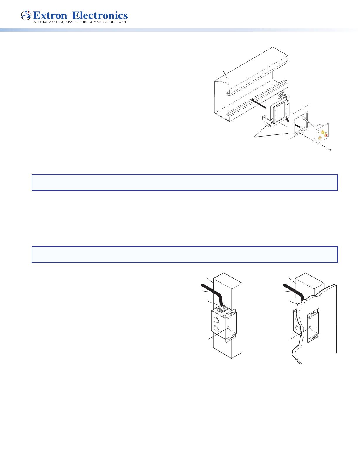
Mounting in a European Cable Channel
1. Remove power from the line driver by disconnecting the
Euro Channel
(not included)
Extron
CVEQ 100 MAAP
Composite Line Driver
VIDEO
IN
CVEQ 100 EU
AUDIO IN
L R
Extron
MAAP 101EUC
Mounting Frame
power supply.
2. Attach the MAAP adapter plate to the junction box.
3. Place the cover frame between the adapter plate and the
line driver, route the output cables through the frame, and
connect them to the line driver.
4. Fasten the line driver to the adapter plate, as shown below.
5. Reconnect the power supply, cable all equipment
(see Operation on page10), and restore power to the equipment.
Installing the CVEQ 100 D/SVEQ 100 D
The CVEQ 100 D and SVEQ 100 D are wall-mounted products and
can be mounted into an electrical wall box. This section includes
site preparation, wall box installation, and the mounting of the line
driver in the wall box.
NOTE: The line driver must be installed into an Underwriters Laboratories (UL) approved electrical wall box. The box
is not included with the line driver; the installer is responsible for obtaining and installing the box.
Preparing the site and installing the wall box
Choose a location that allows cable runs without interference. Allow enough depth for both the wall box and the cables.
You may need to install the cables into the wall or conduits before installing the line driver.
The line driver can be installed in a standard one-gang electrical wall box. The installation must conform to national and
local electrical codes. A dimensional drawing and a cutout template of the line driver are provided in appendix B of this
manual.
NOTE: The cutout template shown in appendix B is not full size. Pay attention to the measurements shown on the
template.
1. Mark the guidelines for the opening on the wall.
Installation Cable
Cable Clamp
Wall Stud
Installation Cable
Cable Clam
p
Wa
ll Stud
Screws or Nails
Screws or Nails
If the line driver will be installed in a wall box, place the
box against the installation surface and draw a line on
it around the outside of the box.
If the line driver will be installed without a wall box
(fastening it directly to the wall), measure and mark the
surface for the cutout area indicated in the cutout
template.
2. Cut out the material from the marked area.
3. Check the opening size by inserting the wall box (if used)
or the line driver (if no box is used) into the opening. The
box and line driver should fit easily into the opening.
Enlarge or smooth the edges of the opening if needed.
4. Feed cables through the wall box punch-out holes, and secure them with cable clamps to provide strain relief.
5. Insert the wall box into the opening, and attach it to the wall or stud using nails or screws. The front edge should be
flush with the outer wall surface. See figure 15.
If attaching the wall box to wood, use four #8 or #10 screws or 10-penny nails. A minimum of ½” (1.3 cm) of
screw threads must penetrate the wood.
If attaching the wall box to metal studs, use four #8 or #10 self-tapping sheet metal screws or machine bolts with
matching nuts.
9
Mounting the Line Driver
Before mounting the line driver and if has not already been tested, test the system to make sure that the connections and
settings are correct see Testing and Troubleshooting.
If the system is operating correctly, the line driver can be installed in the wall. Adjust the gain and equalization, and set
the Audio Out switch to Stereo or Dual Mono before fastening the line driver into the wall box. The controls and cables
will be inaccessible after installation. See Rear Panel Features and Operation on page11 for details about settings
and adjustments.
Continue mounting the line driver by following the steps below.
1. Remove power from the line driver by disconnecting
W
all opening
is flush with
edge of box.
Wall Box
Decorator-Style
Wallplate
Extron
CVEQ 100 D
VIDEO IN
L
R
AUDIO IN
the power supply from the AC source.
2. Connect the output cables to the rear of the device.
3. Place the line driver through the opening in the wall and into
the wall box. Take care not to damage the output cables,
which fit behind the line driver at the back of the wall box.
4. Mount the line driver to the wall box with machine screws
as shown in the following illustration.
5. Attach the decorator-style wall plate to the line driver as
shown in the illustration above.
6. Reconnect the power supply, connect input cables to the
line driver, and restore power to the equipment.
Testing and Troubleshooting
1. Apply power to the line driver. The power/signal LED on the
line driver lights amber (power) or green (video input).
2. If the LED does not light, check the wiring at both the line
driver and the power supply, and make sure the power supply
is connected to a power source.
If the Image Does Not Appear or There is No Sound
1. Make sure that all the devices are powered on.
2. Ensure that the connectors are wired correctly at both ends of the cables. Audio cables must be wired for an
unbalanced stereo input signal and for the appropriate (unbalanced or balanced) output signal.
3. Check the video source’s user’s guide or contact Extron to determine if there are special requirements to output video
to the external video port.
4. Call the Extron S3 Sales and Technical Support Hotline if the image still does not appear or there is no sound.
If the Image is Not Displayed Correctly
1. If the picture is too bright or too dark, or if the edges of the image seem to exceed their boundaries, or if thin lines
and sharp edges look thick and fuzzy, change the gain setting.
If the picture appears and is stable, but it has ghosting or blooming, verify that the video input is properly terminated.
If the problem is not resolved by changing the termination, try using a different input cable. Poor quality or damaged
cable can cause ghosting and blooming.
2. If the picture still is not displayed correctly, call the Extron S3 Sales and Technical Support Hotline.
10
Operation
Front Panel Features and Operation
VIDEO LINE DRIVER
CVEQ 100
GAIN
EQ
1
2a 3
S-VIDEO LINE DRIVER
SVEQ 100
GAIN
EQ
GAIN
Y
C
1
2a 3 2b
CVEQ 100
Front Panel
SVEQ 100
Front Panel
SVEQ 100 AAP
IN
LR
AUDIO IN
1 5
6
CVEQ 100 AAP
VIDEO
IN
RL
AUDIO IN
1 4
6
CVEQ 100 AAP
Front Panel
SVEQ 100 AAP
Front Panel
S-V IDEO
C VEQ 100 MAAP
AUDIO IN
VIDEO IN
RL
CVEQ 100 MAAP
Front Panel
SVEQ 100 MAAP
Front Panel
S-VIDEO IN
AUDIO IN
LR
SVEQ 100 M AAP
1
5
6
1
4
6
VIDEO IN
L
R
AUDIO IN
1
4
CVEQ 100 D
Front Panel
S-VIDEO
IN
AUDIO IN
L
R
1
5
SVEQ 100 D
Front Panel
6 6
Faceplate
Wall Plate
1
Power indicator LED — This LED lights:
Amber when the line driver is receiving full power (this applies to all models except the CVEQ 100 and SVEQ 100,
which light green instead).
Green when the line driver is receiving a video signal (this only applies to the D, AAP, and MAAP models).
Õ
Gain potentiometer (CVEQ 100 and luma of SVEQ 100) — Use a small screwdriver to rotate this potentiometer
to adjust the CVEQ 100’s gain and the SVEQ 100’s luminance gain when the line driver is connected to long output
cables. The adjustment range is -1 dB to +3 dB. The default is unity (the dot position). (See Gain Adjustment
Control on page14.)
11
Ö
Gain potentiometer (chroma of SVEQ 100) — Use a small screwdriver to rotate this potentiometer to adjust the
chroma gain when the SVEQ 100 is connected to long output cables. The adjustment range is 0 dB to +10 dB. The
default is unity (the dot position). (See Gain Adjustment Control on page14.)
3
Equalization (EQ) potentiometer — Use a small screwdriver to rotate
this potentiometer to adjust equalization when the line driver is connected
34
12
PIN NAME DESCRIPTION
1GND Ground (Y)
2GND Ground (C)
3Y Luminance
4CChrominance
S-video Pinout Table
to long output cables. The adjustment range is 0 dB to +7 dB. The default
is set to 0 dB (the dot position). (See Equalization (EQ) Adjustment Control on page14.)
4
Video input connector — Connect a composite video input source to this
RCA connector.
5
S-video input connector — Connect an S-video input source to this
4-pin mini DIN connector. See the pinout table on the right.
6
Audio input connectors — Connect an unbalanced
Tip (+)
Sleeve ( )
stereo audio source to these left (L) and right (R) RCA
connectors. Wire the male connector as shown in the
following illustration.
Rear Panel Features and Operation
LR
INPUT
OUTPUT
12V
0.2A MAX
L
VIDEO
R
VIDEO
1
4a 5
2a
3
CVEQ 100 Rear
Panel
12V
0.2A MAX
L
R
LR
Y
C
Y
C
INPUT OUTPUT
1
53 4b
2b
SVEQ 100 Rear Panel
4a
CVEQ 100 AAP Rear Connectors
5
1
4b
SVEQ 100 AAP Rear Connectors
5
1
12
CVEQ 100 AAP Rear Controls
Y
CVEQ 100 AAP
AUDIO OUTPUT
RL
POWER
12 V
0.2 A MAX
DUAL
MONO
STEREO
EQ
GAIN
To compensate for image degradation
due to long cable runs, adjust the gain
and equalization (EQ) potentiometers.
- Faint, dim, or "soft" images can be
corrected by rotating the gain
potentiometer for maximum brightness.
- To adjust the output level and peaking
for a sharper image, rotate the EQ
potentiometer.
(Top-Down View)
NO CONNECTION
NO CONNECTION
SLEEVE
TIP
TIP
RING
TIP
SLEEVE
RING
TIP
UNBALANCED
+
-
-
+
R
L
BALANCED
L
R
+
-
-
+
Audio Output Wiring
33-1666-01 A 05 08
Extron Electronics
Anaheim, CA
N15779
6 7
9
12V
0.2A MAX
POWER
DUAL
MONO
STEREO
A UDIO OUTPUT
L
R
EQ
VIDEO
GAIN
12V
0.2A MAX
POWER
DUAL
MONO
STEREO
AUDIO OUTPUT
L
R
EQ GAIN
GAIN
C
Y
6
9
7
1
4a
5
CVEQ 100 MAAP Rear Panel
SVEQ 100 MAAP Rear Panel
6
9
7
8
1
4b
5
SVEQ 100 AAP Bottom Controls
Y
SVEQ 100 AAP
AUDIO OUTPUT
RL
POWER
12 V
0.2 A MAX
DUAL
MONO
STEREO
EQ
GAIN
C
GAIN
To compensate for image degradation
due to long cable runs, adjust the gain
and equalization (EQ) potentiometers.
- Faint, dim, or "soft" images can be
corrected by rotating the gain
potentiometer for maximum brightness.
- To adjust the output level and peaking
for a sharper image, rotate the EQ
potentiometer.
(Top-Down View)
NO CONNECTION
NO CONNECTION
SLEEVE
TIP
TIP
RING
TIP
SLEEVE
RING
TIP
UNBALANCED
+
-
-
+
R
L
BALANCED
L
R
+
-
-
+
Audio Output Wiring
33-1667-01 A 05 08
Extron Electronics
Anaheim, CA
N15779
6
7
8
9
9
1
4a
5
CVEQ 100 D Rear Panel
6 7
8
9
1
SVEQ 100 D Rear Panel
4b
5
6 7
1
Power connector — Connect the external 12 VDC power supply into this 2-pin, 3.5 mm direct insertion connector.
The power supply is included with the unit. The “Power supply wiring” section in this chapter explains how to wire
the connector.
Õ
Video input connector — Connect a composite video input source to this BNC connector.
Ö
S-video input connectors — Connect an S-video input source to these BNC connectors.
3
Audio input connectors — Connect an unbalanced stereo audio source to these
Tip (+)
Sleeve ( )
left (L) and right (R) RCA connectors. Wire the male connector as shown in the illustration
on the right.
ã
Video output connector — Connect a composite video output device to this female
BNC connector.
ä
S-video Y connector (luma, white cable) — Connect the luma of an S-video output device to this female BNC
connector.
S-video C connector (chroma, yellow cable) — Connect the chroma of an S-video output device to this female
BNC connector.
5
Audio output connector — Wire a balanced/unbalanced audio output device to this 3.5 mm, 5-pole, direct
insertion captive screw connector. See the wiring diagrams on the next page.
13
NOTE: Balanced audio is more resistant to noise and can be driven for longer distances than unbalanced audio.
For best results, wire the output for balanced audio.
Balanced Stereo
Sleeve (s)
Left Tip (+)
Left Ring (-)
Right Tip (+)
Right Ring (-)
Set Audio Out switch to Stereo.
Balanced Mono
Sleeve
Tip (+)
Ring (-)
Unbalanced Stereo
Sleeve
Left Tip (+)
Right Tip (+)
Use either the left or the right channel.
Unbalanced Mono
Sleeve
Tip (+)
Use either the left or the right channel.
Set Audio Out switch to Dual Mono. Set Audio Out switch to Dual Mono.
Set Audio Out switch to Stereo.
Do not tin the wires!
CAUTION Connect the sleeve to ground
(Gnd).
Connecting the sleeve to
a negative (–) terminal will
damage the audio output
6
Output equalization (EQ) potentiometer — Use an Extron Tweeker (a small screwdriver) to rotate this control to
adjust equalization when the line driver is connected to long output cables. The adjustment range is 0 dB to +7 dB.
The default is set to 0 dB (the dot position). (See Equalization (EQ) Adjustment Control on page14).
7
Output gain potentiometer (luma) — Use an Extron Tweeker (a small screwdriver) to rotate this control to
adjust the CVEQ’s gain or the SVEQ’s luminance gain when the line driver is connected to long output cables. The
adjustment range is -1 dB to +3 dB. The default is unity (the dot position). (See Gain Adjustment Control on
page14.)
8
Output gain potentiometer (chroma) — Use an Extron Tweeker (a small screwdriver) to rotate this control to
adjust the SVEQ’s chrominance gain when the line driver is connected to long output cables. The adjustment range
is 0 dB to +10 dB. The default is unity (the dot position). (See Gain Adjustment Control on page14.)
9
Audio output select switch — Use this switch to select either stereo (up) or dual mono (down) output. When set
for dual mono, the left and right channels output the same signal (either channel or both channels can be used). The
audio output can be wired for balanced/unbalanced mono or stereo output. The wiring and the switch setting must
match.
Power Supply Wiring
Wire the line driver’s power connector as shown on the
right.
Power Supply
Output Cord
SECTION A–A
Ridges
Smooth
AA
Captive Screw
Connector
3
5
NOTE: The CVEQ 100 and SVEQ 100 use a
pre-wired captive screw power connector. The
D, AAP, and MAAP models use direct insertion
connectors.
ATTENTION: Power supply voltage polarity is
critical. Incorrect voltage polarity can damage
the power supply and the line driver. Identify the
power cord negative lead by the ridges on the
side of the cord.
To verify the polarity before connection, plug in the power supply with no load and check the output with a voltmeter.
14
CAUTION:
The two power cord wires must be kept separate while the power supply is plugged in. Remove the power
before wiring.
Les deux cordons d’alimentation doivent rester séparés tant que l’alimentation est branchée. Coupez
l’alimentation avant de faire les raccordements..
NOTE: Do not tin the power supply leads before installing in the direct insertion connector. Tinned wires are not as
secure in the connectors and could be pulled out.
Gain Adjustment Control
The gain control adjusts picture brightness by compensating for signal amplitude loss caused by cable resistance. To
adjust the output gain, view the display while using a small, flat-blade screwdriver to rotate the potentiometer. This
control produces a gain adjustment ranging from -1 dB to + 3 dB (CVEQ and luma of SVEQ) and from 0 dB to +10 dB
(chroma of SVEQ). Select the setting that gives the best picture brightness.
CVEQ 100 Series
SVEQ 100 Series
NOTE: The gain control is a potentiometer with a mechanical stop at the high and the low end. After you have
reached the high or low end of the adjustment, no change is apparent on the display. The default is unity (the dot
position).
You can judge the adjustment visually by viewing the display. For a more precise setting use an oscilloscope or a
waveform monitor connected to the far end of the output cable, and adjust the gain so that the level at the waveform
monitor is 100 IRE.
Equalization (EQ) Adjustment Control
The equalization control adjusts the output level and peaking to get a sharp picture. This adjustment changes the level
and peaking of the output signal to compensate for capacitance caused by up to 1000 feet (300 meters) of Extron MHR
cable.
This control produces an equalization adjustment ranging from 0 dB to + 7 dB (CVEQ and luma of SVEQ).
CVEQ 100 Series
SVEQ 100 Series
Use a small, flat-blade screwdriver to rotate this control. View the display and select the setting that gives the sharpest
picture. For a more precise setting, you can use an oscilloscope or a waveform monitor connected to the far end of the
output cable, and adjust the equalization so that the color burst ranges between -20 IRE and +20 IRE.
NOTE: The EQ control is a potentiometer with a mechanical stop at the high and the low end. After you have
reached the high or low end of the adjustment, no change is apparent on the display. The default is set to 0 dB
(the dot position).
15
Replacing the Decorator-Style Faceplate (CVEQ 100 D and SVEQ 100 D)
The front faceplate is replaced by removing the two rear panel mounting
Faceplate (rear)
Rear Panel
Mounting
Screws
screws, replacing the faceplate, then reattaching the two screws, as shown
in the CVEQ 100 D example on the right.
NOTE: The faceplate for the SVEQ 100 D is replaced in similar fashion.
Decorator-Style Models Dimensions
Dimensions are shown in inches [mm}.
.0000 [0.000]
.000 [0.000]
1.700 [43.00]
2X 0.050 [1.270]
0.155 [3.937]
1.445 [36.703]
1.550 [39.370]
1.600 [40.640]
0.000 [0.000]
0.060 [1.524]
0.100 [2.540]
0.225 [5.715]
0.000 [0.000]
0.000 [0.000]
2.720 [70.000]
0.110 [2.794]
0.790 [20.066]
1.465 [37.211]
2.040 [51.816]
2.720 [69.088]
2.830 [71.882]
.060 [1.524]
.100 [2.540]
.600 [15.500]
Front View Side View
16
Cut-out Template
NOTE: Always check and go by the dimensions given in this guide. The template is not full size.
CSVEQ 100 D
Cut-Out Template for the Extron
4.50"
(11.43 cm)
To install
line driver
directly into
furniture or wall,
cut along this line.
Wall Plate
SURFACE
CUT-OUT AREA
FOR
FURNITURE
MOUNT
2.79"
(7.09 cm)
1.75"
(4.5 cm)
2.8"
(7.1 cm)
Location of Line Driver
TEMPLATE IS NOT FULL SIZE
1 / 1

Extron CVEQ 100 User manual

Category
Wall & ceiling mounts accessories
Type
User manual
This manual is also suitable for

Ask a question and I''ll find the answer in the document

Finding information in a document is now easier with AI

Ask the document