Page is loading ...

PROGRAMMING GUIDE
XT SERIES™ PANELS

Digital Monitoring Products, Inc. XT Series Programming Guide
b
MODEL XT30/XT50
PROGRAMMING GUIDE
When using the XT30/XT50 Series control panel for any listing organization’s approved methods, refer to this
manual and the XT30/XT50 Installation Guide (LT-0980). These documents outline the installation and programming
requirements of all applications for which the XT30/XT50 is approved.
FCC Notice
This equipment generates and uses radio frequency energy and, if not installed and used properly in strict
accordance with the manufacturer’s instructions, may cause interference with radio and television reception. It
has been type tested and found to comply with the limits for a Class B computing device in accordance with the
specication in Subpart J of Part 15 of FCC Rules, which are designed to provide reasonable protection against such
interference in a residential installation. If this equipment does cause interference to radio or television reception,
which can be determined by turning the equipment off and on, the installer is encouraged to try to correct the
interference by one or more of the following measures:
• Reorient the receiving antenna
• Relocate the computer with respect to the receiver
• Move the computer away from the receiver
• Plug the computer into a different outlet so that computer and receiver are on different branch circuits
If necessary, the installer should consult the dealer or an experienced radio/television technician for additional
suggestions. The installer may nd the following booklet, prepared by the Federal Communications Commission,
helpful:
“How to identify and Resolve Radio-TV Interference Problems.”
This booklet is available from the U.S. Government Printing Ofce, Washington D.C. 20402
Stock No. 004-000-00345-4
This device complies with part 15 of the FCC Rules. Operation is subject to the following two conditions: (1) This
device may not cause harmful interference, and (2) this device must accept any interference received, including
interference that may cause undesired operation.
Industry Canada
This device complies with Industry Canada license-exempt RSS standard(s). Operation is subject to the following two
conditions: (1) this device may not cause interference, and (2) this device must accept any interference, including
interference that may cause undesired operation of the device.
© 2018 Digital Monitoring Products, Inc.
Information furnished by DMP is believed to be accurate and reliable.
This information is subject to change without notice.

XT Series Programming Guide Digital Monitoring Products, Inc.
i
TABLE OF CONTENTS
Introduction .......................................................................................... 1
1.1 Before You Begin ................................................................................................ 1
1.2 Getting Started ................................................................................................... 1
1.3 Programmer Menu .............................................................................................. 2
1.4 Programmer Lockout Codes ................................................................................. 2
1.5 Reset Timeout .................................................................................................... 3
1.6 Keypads ............................................................................................................. 3
1.7 Special Keys ....................................................................................................... 4
1.8 Entering Characters Using the Number Pad ........................................................... 5
1.9 Entering Characters Using the Standard Keyboard ................................................. 5
1.10 Keypad Displays Current Programming ................................................................. 5
Initialization .......................................................................................... 6
2.1 Initialization........................................................................................................ 6
2.2 Clear All Codes ................................................................................................... 6
2.3 Clear All Schedules .............................................................................................. 6
2.4 Clear Events ....................................................................................................... 6
2.5 Clear Zone Programming ..................................................................................... 6
2.6 Clear Communication .......................................................................................... 6
2.7 Clear Wi-Fi ......................................................................................................... 6
2.8 Set to Factory Defaults ........................................................................................ 6
Communication ..................................................................................... 7
3.1 Communication ................................................................................................... 7
3.2 Account Number ................................................................................................. 7
3.3 Transmission Delay ............................................................................................. 7
3.4 Communication Type ........................................................................................... 7
3.5 Backup Dialer ..................................................................................................... 7
3.6 Backup Cellular ................................................................................................... 7
3.7 Test Time ........................................................................................................... 7
3.8 Test Days ........................................................................................................... 7
3.9 Check-in Minutes ................................................................................................ 8
3.10 Fail Time ............................................................................................................ 8
3.11 Send Communication Trouble ............................................................................... 8
3.12 First GPRS APN ................................................................................................... 8
3.13 Second GPRS APN ............................................................................................... 8
3.14 Receiver 1 Programming...................................................................................... 8
3.15 Alarm Reports ..................................................................................................... 8
3.16 Supervisory/Trouble Reports ................................................................................ 8
3.17 Opening/Closing and User Reports ....................................................................... 8
3.18 Test Report ......................................................................................................... 8
3.19 First Telephone Number ...................................................................................... 9
3.20 Second Telephone Number .................................................................................. 9
3.21 First IP Address .................................................................................................. 9
3.22 First IP Port ........................................................................................................ 9
3.23 Second IP Address .............................................................................................. 9
3.24 Second IP Port .................................................................................................... 9
3.25 Receiver 2 Programming...................................................................................... 9
3.26 Alarm Reports ..................................................................................................... 9
3.27 Supervisory/Trouble Reports ...............................................................................10
3.28 Opening/Closing and User Reports ......................................................................10
3.29 Test Report ........................................................................................................10
3.30 First Telephone Number .....................................................................................10
3.31 Second Telephone Number .................................................................................10
3.32 First IP Address .................................................................................................10
3.33 First IP Port .......................................................................................................10
3.34 Second IP Address .............................................................................................10
3.35 Second IP Port ...................................................................................................10

Digital Monitoring Products, Inc. XT Series Programming Guide
ii
TABLE OF CONTENTS
Network Options ................................................................................. 11
4.1 Network Options ................................................................................................11
4.2 Wi-Fi Setup .......................................................................................................11
4.2.1 WPS..................................................................................................................11
4.2.2 List ...................................................................................................................11
4.2.3 Manual ..............................................................................................................11
4.2.4 Test ..................................................................................................................12
4.3 Wireless Security Type ........................................................................................12
4.4 Wireless Network Key .........................................................................................12
4.5 DHCP ................................................................................................................12
4.6 Local IP Address ................................................................................................12
4.7 Gateway Address ...............................................................................................12
4.8 Subnet Mask......................................................................................................12
4.9 DNS Server........................................................................................................12
4.10 Programming Port ..............................................................................................12
Messaging Setup ................................................................................. 13
5.1 Messaging Setup ................................................................................................13
5.2 Enable Messaging ..............................................................................................13
5.3 System Name ....................................................................................................13
5.4 Destination 1 .....................................................................................................13
5.5 Destination 1 User Number .................................................................................13
5.6 Destination 2 .....................................................................................................13
5.7 Destination 2 User Number .................................................................................13
5.8 Destination 3 .....................................................................................................13
5.9 Destination 3 User Number .................................................................................13
5.10 Email Communication Type .................................................................................14
5.11 O/C Email ..........................................................................................................14
5.12 O/C SMS ...........................................................................................................14
5.13 Monthly Limit .....................................................................................................14
5.14 SMTP Server ......................................................................................................14
5.15 SMTP Server Port ...............................................................................................14
5.16 SMTP Username ................................................................................................14
5.17 SMTP Password .................................................................................................14
5.18 From Email Address ...........................................................................................14
Device Setup ....................................................................................... 15
6.1 Device Setup .....................................................................................................15
6.2 Device Number ..................................................................................................15
6.3 Device Name .....................................................................................................15
6.4 Wireless ............................................................................................................15
6.5 Serial Number....................................................................................................15
6.6 Supervision Time ...............................................................................................15
Remote Options .................................................................................. 16
7.1 Remote Options .................................................................................................16
7.2 Remote Key .......................................................................................................16
7.3 Manufacturer Authorization .................................................................................16
7.4 Armed Rings ......................................................................................................16
7.5 Disarmed Rings .................................................................................................16
7.6 Alarm Receiver Authorization ..............................................................................16
7.7 Service Receiver Authorization ............................................................................16
7.8 Remote Disarm ..................................................................................................17
7.9 App Key ............................................................................................................17
System Reports ................................................................................... 17
8.1 System Reports .................................................................................................17
8.2 Opening/Closing Reports ....................................................................................17
8.3 Abort Reports ....................................................................................................17
8.4 Zone Restoral Reports ........................................................................................17

XT Series Programming Guide Digital Monitoring Products, Inc.
iii
TABLE OF CONTENTS
8.5 Bypass Reports ..................................................................................................17
8.6 Code Change Reports .........................................................................................18
8.7 Ambush ............................................................................................................18
8.8 Late To Open .....................................................................................................18
8.9 Early To Close ....................................................................................................18
System Options ................................................................................... 18
9.1 System Options .................................................................................................18
9.2 System ..............................................................................................................18
9.3 Closing Code .....................................................................................................18
9.4 Closing Check ....................................................................................................18
9.5 Entry Delay 1 .....................................................................................................18
9.6 Exit Delay ..........................................................................................................19
9.7 Cross Zone Time ................................................................................................19
9.8 Power Fail Delay ................................................................................................19
9.9 Swinger Bypass Trips .........................................................................................19
9.10 Reset Swinger Bypass ........................................................................................19
9.11 Telephone Access ...............................................................................................19
9.12 Zone Activity Hours ............................................................................................20
9.13 Arm Activity Days ...............................................................................................20
9.14 Time Zone Changes ...........................................................................................20
9.15 Time Display......................................................................................................21
9.16 House Code .......................................................................................................21
9.16.1 Detect Wireless Jamming ...................................................................................21
9.16.2 Wireless Audible Annunciation ............................................................................21
9.17 Built-In 1100 Wireless (XT50 only) ......................................................................21
9.18 Enable Keypad Panic Keys ..................................................................................21
9.19 Occupied Premises .............................................................................................21
9.20 Use False Alarm Question ...................................................................................22
9.21 Weather Zip Code ..............................................................................................22
Bell Options ......................................................................................... 23
10.1 Bell Options .......................................................................................................23
10.2 Bell Cutoff Time .................................................................................................23
10.3 Automatic Bell Test ............................................................................................23
10.4 Bell Output ........................................................................................................23
10.5 Bell Action .........................................................................................................23
10.5.1 Fire ...................................................................................................................23
10.5.2 Burglary ............................................................................................................23
10.5.3 Supervisory .......................................................................................................23
10.5.4 Panic .................................................................................................................23
10.5.5 Emergency ........................................................................................................23
10.5.6 Auxiliary 1 .........................................................................................................23
10.5.7 Auxiliary 2 .........................................................................................................23
Output Options .................................................................................... 24
11.1 Output Options ..................................................................................................24
11.2 Cutoff Outputs ...................................................................................................24
11.2.1 Output Cutoff Time ............................................................................................24
11.3 Communication Failure Output ............................................................................24
11.4 Fire Alarm Output ..............................................................................................24
11.5 Fire Trouble Output ............................................................................................24
11.6 Panic Alarm Output ............................................................................................24
11.7 Ambush Output .................................................................................................24
11.8 Entry Output .....................................................................................................24
11.9 Begin Exit Output ...............................................................................................25
11.10 End Exit Output .................................................................................................25
11.11 Ready Output ....................................................................................................25
11.12 Armed Output ....................................................................................................25
11.13 Disarmed Output ...............................................................................................25

Digital Monitoring Products, Inc. XT Series Programming Guide
iv
TABLE OF CONTENTS
11.14 Burglary Output .................................................................................................25
11.15 Late To Close Output ..........................................................................................25
11.16 Arm-Alarm Output ..............................................................................................25
11.18 Cool Saver Temperature .....................................................................................25
Output Information ............................................................................. 26
12.1 Output Information ............................................................................................26
12.2 Output Number .................................................................................................26
12.3 Output Name .....................................................................................................26
12.4 Serial Number....................................................................................................26
12.5 Supervision Time ...............................................................................................26
12.6 Trip with Panel Bell Option ..................................................................................26
Area Information ................................................................................. 27
13.1 Area Information ...............................................................................................27
13.2 Area Number .....................................................................................................27
13.3 Area Name ........................................................................................................27
13.4 Automatic Arming ..............................................................................................27
13.4.1 Bad Zones .........................................................................................................27
13.5 Automatic Disarming ..........................................................................................27
Zone Information ................................................................................ 28
14.1 Zone Information ...............................................................................................28
14.2 Zone Number ....................................................................................................28
14.3 Key Fob .............................................................................................................28
14.4 Zone Name........................................................................................................28
14.5 Zone Type .........................................................................................................28
14.6 Area Assignment ................................................................................................29
14.7 Arming Zone Assignment ....................................................................................29
14.7.1 Style .................................................................................................................29
14.8 Next Zone .........................................................................................................30
DMP Wireless ....................................................................................................30
14.9 Wireless ............................................................................................................30
14.9.1 Serial Number Entry ...........................................................................................30
14.9.2 Contact .............................................................................................................30
14.9.3 Supervision Time ...............................................................................................31
14.9.4 LED Operation ...................................................................................................31
14.9.5 Disarm/Disable ..................................................................................................31
14.9.6 Wireless PIR Pulse Count ....................................................................................31
14.9.7 Wireless PIR Sensitivity ......................................................................................31
14.9.8 Next Zone .........................................................................................................31
14.10 1100 Series Key Fobs .........................................................................................32
14.10.1 Key Fob User Number ........................................................................................32
14.10.2 Key Fob Serial Number .......................................................................................32
14.10.3 Key Fob Supervision Time ...................................................................................32
14.10.4 Number of Key Fob Buttons ................................................................................32
14.10.5 Key Fob Button Selection (Four Buttons) ..............................................................32
14.10.6 Key Fob Button Selection (Two Buttons) ..............................................................32
14.10.7 Button Action ....................................................................................................33
14.10.8 Button Press Time ..............................................................................................33
14.10.9 Arm/Disarm Area Selection .................................................................................33
14.10.10 Output Number .................................................................................................33
14.10.11 Output Action ....................................................................................................33
14.11 Alarm Action ......................................................................................................34
14.12 Disarmed Open ..................................................................................................34
14.12.1 Message To Transmit ..........................................................................................34
14.12.2 Output Number .................................................................................................35
14.12.3 Output Action ....................................................................................................35
14.13 Swinger Bypass .................................................................................................35
14.14 Prewarn Address ................................................................................................35

XT Series Programming Guide Digital Monitoring Products, Inc.
v
TABLE OF CONTENTS
14.15 Entry Delay .......................................................................................................35
14.16 Cross Zone ........................................................................................................36
14.17 Priority ..............................................................................................................36
14.18 TrafcCount ......................................................................................................36
14.19 Zone Audit Days ................................................................................................36
14.20 Receiver Routing ................................................................................................36
14.21 Zone Number ....................................................................................................36
Stop ............................................................................................... 37
15.1 Stop ..................................................................................................................37
Set Lockout Code ................................................................................ 37
16.1 Set Lockout Code ...............................................................................................37
Appendix ............................................................................................. 38
17.1 Status List .........................................................................................................38
17.2 False Alarm Reduction ........................................................................................38
17.3 Diagnostics Function ..........................................................................................38
17.4 Using the 984 Command Function .......................................................................40
17.5 Using the Walk Test ...........................................................................................41
Walk Test ..........................................................................................................41
Trip Counter for Walk Test (STD) .........................................................................41
Test End Warning ...............................................................................................41
Failed Zones Display ...........................................................................................41
17.6 Keypad Speaker Operation..................................................................................42
17.7 Cross Zoning .....................................................................................................42
17.8 Zone Type Descriptions ......................................................................................42
17.9 Common Keypad Messages ................................................................................43
17.10 Z-WaveCerticationInformation .........................................................................43
Revisions to this Document ................................................................ 44

XT Series Programming Guide Digital Monitoring Products, Inc.
1
INTRODUCTION
Introduction
1.1 Before You Begin
Before programming the panel, we recommend you read through the contents of this manual. The
information in this document allows you to learn the programming options and operational capabilities
of the XT30/XT50 panel. After this Introduction, the remaining sections describe the functions of
each programming menu items along with their available options. The XT30/XT50 contains all of its
programming information in an on-board processor and does not require an external programmer.
In addition to this manual, you should also be familiar with the following XT30/XT50 Series documents:
• XT30/XT50 Installation Guide (LT-0980)
• XT30/XT50 User Guide (LT-0982)
• XT30/XT50 Programming Sheet (LT-0983)
Programming Sheets
Included with each XT30/XT50 Series panel is the panel programming sheet. This sheet lists the various
options available for programming the panel. Before starting, completely ll out the sheet with the
programming options you intend to enter into the panel. Having completed programming sheets
available while entering data helps to prevent errors and can shorten the length of time you spend
programming. Completed sheets also provide you with an accurate account of the panel’s program you
can keep on le for future system service or expansion. The remainder of the Introduction explains
starting and ending a programming session.
1.2 Getting Started
The panel must be properly grounded before connecting any devices or applying power to the panel.
Proper grounding protects against Electrostatic Discharge (ESD) that can damage system components.
Before programming the panel, make sure the panel is properly grounded and AC and battery power is
applied to the appropriate panel terminals. All wiring connections and grounding instructions are detailed
in the XT Series Installation Guide (LT-0980).
Program from any Keypad Address or Wireless Keypad
You can program the panel from any 32-character wireless keypad or hardwired keypad connected to
the panel’s keypad data bus.
Hardwired Keypad Connection
Connect the DMP Model 300 4-wire harness to the hardwired keypad. Observe wire colors when
connecting the red, yellow, green, and black wires to the keypad bus. Connect red to panel terminal
7, yellow to terminal 8, green to 9, and black to panel terminal 10 or connect a DMP Model 330
Programming Cable from the keypad to the PROG port on the control panel. You can perform all
programming tasks through a 32-character DMP keypad set to address one. Using a hard-wired
keypad, wireless keypads can be programmed into the panel manually or by using the Wireless Keypad
Association operation.
Wireless Keypad Association
Enable Wireless Keypad Association operation on both the keypad and panel.
Wireless LCD Keypad
1. Press and hold the back arrow key and CMD at the same time until SET BRIGHTNESS displays.
2. Enter the code 3577 (INST) and press CMD.
3. Select KPD RF to start the RF survey communication. The keypad displays its wireless serial
number and RF SURVEY.
Wireless Graphics Touchscreen Keypad
1. Press Options in the carousel menu.
2. Press the wrench icon to access the Installer Options menu.
3. Enter the code 3577 (INST) and press CMD.
4. Press KPD RF to start the RF survey communication. The keypad displays its wireless serial
number and RF SURVEY.
Enable in the XT30/XT50 Series panel
Reset the panel three times, allowing the keypad bus transmit light to begin ashing between each
reset. For 60 seconds the panel listens for wireless keypads that are in RF Survey mode and have
not been programmed or associated into another panel. When the keypad associates with the panel
the keypad logo LED turns from red to green. Wireless keypads are assigned to the rst open device
position in Device Setup automatically based upon the order in which they are detected.

Digital Monitoring Products, Inc. XT Series Programming Guide
2
INTRODUCTION
Accessing the Programmer Menu
1. Connect the keypad to the PROG header.
2. If using a Wireless LCD Keypad, make sure panel communication has been established and the user
menu appears on an associated keypad before continuing.
3. Install the reset jumper across the two RESET pins on the panel for two seconds.
4. Remove the reset jumper and place it over just one pin for future use.
5. Enter the code 6653 (PROG). The keypad displays PROGRAMMER.
1.3 Programmer Menu
You are now ready to start programming the XT30/XT50 panel. Press CMD to scroll through the
programmer menu items listed below.
Menu Item Section in This Manual Menu Item Section in This Manual
Initialization 2 Bell Options 10
Communication 3 Output Options 11
Network Options 4 Output Information 12
Messaging Setup 5 Area Information 13
Device Setup 6 Zone Information 14
Remote Options 7 Stop 15
System Reports 8 Set Lockout Code 16
System Options 9 Appendix 17
Select a programmer menu item by pressing any select key or area when the name of that menu item
displays on the keypad. The detailed instructions for each programming step are found in this manual.
1.4 Programmer Lockout Codes
Although the XT30/XT50 panels allow you to access the Programmer menu without a lockout code, it is
recommended you program one to restrict programming access to authorized individuals only. See Set
Lockout Code.
Installing a lockout code
1. After entering the Programmer menu, the keypad displays PROGRAMMER. Press CMD until SET
LOCKOUT CODE displays (after STOP).
2. Press any select key or area. At ENTER CODE: -, enter a 1 to 5-digit lockout code. Press CMD.
3. At ENTER AGAIN, enter the same lockout code again and press CMD. The display shows CODE
CHANGED. The new code number must now be entered before the Programmer menu can be
accessed. The lockout code should be written down and kept in a secure place with access limited
to authorized persons only.
Lost Lockout Code requires factory reset: If you lose or forget the lockout code, the panel must
be sent back to the factory to be reset. There is no eld option for gaining access to the panel
without a valid lockout code.

XT Series Programming Guide Digital Monitoring Products, Inc.
3
INTRODUCTION
1.5 Reset Timeout
The XT30/XT50 has a feature that requires you to enter the Programmer menu within 30 minutes of
resetting the panel. After 30 minutes, if you attempt to program by entering the 6653 (PROG) code, the
keypad displays RESET PANEL. You must reset the panel and enter the program code within the next 30
minutes.
If you are already in the Programmer menu and do not press any keys on the programming keypad for 30
minutes, the panel stops programming. All data entered up to that point is saved in the panel’s memory.
Using the STOP function disarms all areas: To exit the Programmer menu, you must use the Stop
function. STOP is the second to the last option in the Programmer menu. The Stop function disarms all
areas and clears the keypad’s Status List. The programming session is then terminated and the keypad
returns to the Status List or Main Screen.
1.6 Keypads
DMP offers many different keypads that provide panel programming capabilities. Each keypad and its
operations are shown and described in the following sections.
Note: Programming cannot be accessed using an Icon Series keypad. Use a keypad type shown below.
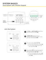
32-Character Display
Armed LED
Power LED
Data Entry Digit keys
COMMAND Key
Back Arrow Key
Select Keys
1 2 3 4
9 0 CMD
5 6 7 8
ABC PRINTING
FRI 2:51 AM
Backlit Logo
and Proximity
Antenna
Figure 1: Wireless Keypad
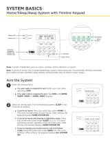
Icon Display
Shortcut and Digit keys
Backlit Logo
and Proximity
Antenna
COMMAND Key
Back Arrow Key
Select Keys
Figure 2: Thinline/Aqualite Keypad
32-Character Display
Data Entry Digit keys
COMMAND Key
Back Arrow Key
Select Keys
Backlit Logo
and Proximity
Antenna
SMITH RESIDENCE
FRI 12: 51 PM
Figure 3: Icon Keypad
MON 5:35 AM
DISARMED
Panic
Chime
Check-In
Reset
Interactive Shield
Proximity Card
Reader
Micro SD
Card Slot
Carousel
Menu
Dealer
Logo
Local Weather
Conditions
TODAY
WEDNESDAY
82
98 77
80
LO
74
HI
HI LO
CURRENT
Figure 4: Graphic Touchscreen Keypad

Digital Monitoring Products, Inc. XT Series Programming Guide
4
INTRODUCTION
1.7 Special Keys
The following special keys or areas are common to all DMP keypads.
CMD (Command) Key
Pressing CMD allows you to go forward through the programming menu and through each step of a
programming sec tion. As you go through the programming, the keypad display shows any current
programming already stored in the panel memory. If no change is required for an option, press CMD to
advance to the next step.
CMD is also used to enter information into the panel’s memory such as phone numbers or zone names.
Press CMD after entering information.
<— (Back Arrow) Key
Use the back arrow key to back up one step while programming. The back arrow key is also used when
an error is made while entering in formation. Press the back arrow key once to erase the last character
entered.
Select Keys or Areas
On LCD keypads, the top row of keys are called the select keys. On Graphic Touchscreen Keypads, the
keypad is sectioned into select areas. Each time you need to press a select key or area, the keypad
displays the function or options above one of the select keys or in the select area. Displaying choices
above individual select keys or in select areas allows them to be used for many different applications.
For example, you can enter AM or PM when programming the automatic test time or answer YES or NO
for a system option.
During programming, the select keys or areas also allow you to change infor mation currently in panel
memory by pressing the appropriate select key or area under or on the display. You then enter the new
information using the keypad data entry digit keys.
When there are more than four re sponse options avail able, press CMD to display the next one to four
options. Pressing the back arrow key allows you to review the previous four choices.
The select keys or areas are also used for choosing a section from the pro gramming menu. Press any
select key or touch the select area when the programming section name you want displays.
Note: For LCD Keypads, when instructed to press the rst select key, press the far left select key; the
second select key is the second from the left; third select key is second from the right; and the fourth
select key is the far right key. See Figures 6 and 7.
For Graphic Touchscreen Keypads, when instructed to press the rst select key, touch select area 1;
the second select key touch select area 2; third select key touch select area 3; and the fourth select
key touch select area 4.

XT Series Programming Guide Digital Monitoring Products, Inc.
5
INTRODUCTION
1.8 Entering Characters Using the Number Pad
1. Choose a character from the table.
2. Identify the Number the character correlates with and
press it on the number pad.
3. Identify the Select Key or Area for that character and
press that select key or area on the keypad. To access
the lowercase letter, press that select key or area
again. See Figure 5.
4. When the desired character displays on the keypad,
return to Step 1 to enter another character or press
CMD if nished.
1.9 Entering Characters Using the Standard Keyboard
• Press ABC to access uppercase letters.
• Press abc to access lowercase letters.
• Press !@# to access symbols.
• Press 123 to access the number pad.
Note: Keep in mind that not all keypad prompts
accept letters and/or symbols. For example,
pressing P on the ENTER CODE prompt could display
a 6 on the keypad. See Figure 6.
1.10 Keypad Displays Current Programming
Each programming option displayed at the keypad shows the currently selected option in the panel
memory. These options are either shown as a number, a blank, or a NO or YES. To change a number or
blank to a new number, press any top row select key or touch any select area. The current option is
replaced with a dash. Press the number(s) on the keypad you want to enter as the new number for that
option. It is not necessary to enter numbers with leading zeros. The panel automatically right justies the
number when you press CMD.
To change a programming option that requires a NO or YES response, press the select key or touch the
select area for the response not selected. See Figure 8.
For example, if the current option is selected as YES and you want to change it to NO, on LCD Keypads,
press the third top row select key. On Graphic Touchscreen Keypads touch select area 3. The display
changes to NO. Press CMD to display the next option.
THEN
Press the black colored top
row Select key/area.
The keypad displays the new
selection. Press CMD to advance.
YESBELL TST
NOBELL TST
YESBELL TST
NOBELL TST
Thinline,
Aqualite,
Wireless
Keypads
Graphic
Keypads
Figure 7: Changing the Current Programming Option
NUMBER
SELECT KEY OR AREA
1 2 3 4
1 A B C ( [ {
2 D E F ) ] }
3 G H I ! ^ ~
4 J K L ? “ |
5 M N O / \ `
6 P Q R & $
7 S T U @ %
8 V W X , =
9 Y Z space, : _ ;
0 -, + ., ‘ *, < # >
ABC
!@#
123
q w e r t y u i
o p
a s d f g h j k l
z
x c v b n m CMD
Figure 6: Standard Keyboard
Figure 5: Number Pad Characters

Digital Monitoring Products, Inc. XT Series Programming Guide
6
INITIALIZATION
Initialization
2.1 Initialization
This function allows you to set the panel’s programmed memory back to the factory
defaults. Select YES to clear the rst section of memory. The panel asks if you are
sure you want to clear that section’s memory. This is a safeguard against accidently
erasing part of the panel programming. No memory is cleared from the panel until
you answer YES to the SURE? YES NO option.
2.2 Clear All Codes
NO leaves existing codes intact.
YES clears the user code memory and assigns the user code number 99 to user 30 on
the XT30, and 99 on the XT50.
2.3 Clear All Schedules
NO leaves existing schedules intact.
YES clears all schedules from the XT30 or XT50 programming.
2.4 Clear Events
NO leaves existing event memory intact.
YES clears all event memory currently held in the panel’s Display Events buffer.
2.5 Clear Zone Programming
NO leaves existing zone information intact.
YES sets all zones in the system to * UNUSED *
2.6 Clear Communication
NO leaves existing communication, network, and e-mail programming intact.
YES clears communication, network and e-mail programming to factory defaults.
2.7 Clear Wi-Fi
NO leaves existing Wi-Fi programming intact.
YES clears Wi-Fi programming to factory defaults.
2.8 Set to Factory Defaults
NO leaves the remainder of the existing panel programming intact.
YES sets the panel’s programming back to factory default selections and clears all
Z-Wave, Favorites, Device Setup, System Options, and Remote Options programming
from the panel. Selecting YES does not clear the panel’s event memory, zone, user
code information, or schedules.
INITIALIZATION
CODES? NO YES
SURE? YES NO
SCHEDS? NO YES
SURE? YES NO
EVENTS? NO YES
SURE? YES NO
ZONES? NO YES
SURE? YES NO
COMM? NO YES
SURE? YES NO
WIFI? NO YES
SURE? YES NO
DEFAULTS? NO YES
SURE? YES NO

XT Series Programming Guide Digital Monitoring Products, Inc.
7
COMMUNICATION
Communication
3.1 Communication
The Communication section allows you to congure the communication settings for
the XT30/XT50 panel. After choosing the Communication Type, continue through the
list of options.
3.2 Account Number
Enter the account num ber sent to the receiver.
DD, NET, CELL - The range of account numbers for Digital Dialer, Network, and Cell
is 1 to 65535. For account numbers of four digits or less, you do not have to enter
leading zeros. The panel automatically right justies the account number.
CID - The account number range for this format is 1 - 9999.
3.3 Transmission Delay
Enter the number of seconds (15 to 45 seconds) the panel waits before sending
burglary alarm reports to the receiver. The bell and relay outputs are not delayed
during this period. Program Burglary Outputs for steady, and set Abort Reports to
YES if Opening and Closing reports are not being sent. Enter 0 (zero) to disable this
function. The default is 30.
If the area where the alarm occurred is disarmed during the Transmit Delay time,
only an Abort Report (S45) message is sent to the receiver. If the area where the
alarm occurred is disarmed after the alarm message is sent to the receiver but
before the Bell Cutoff time expires, even if the alarm was silenced, an Alarm
Cancelled (S49) message is sent. The Alarm Cancelled report cannot be disabled.
3.4 Communication Type
This species the communication method the panel uses to contact the receiver.
Press any select key or area to display the following communication options:
DD - Digital Dialer communication to DMP SCS-1R.
CID - Contact ID dialer communication to non-DMP receivers. This format sends the
report codes of the Ademco Contact ID communication format.
NET - Network communication to DMP Model SCS-1R Receivers or SCS-VR Receivers.
CELL - Cellular communication to DMP Model SCS-1R or SCS-VR Receivers.
WIFI - Network communication to DMP Model SCS-1R or SCS-VR Receivers.
NONE - For local systems. Selecting this ends communication programming.
Note: The Backup Dialer, Backup Cellular, Check-in Minutes, and Failed Minutes
options revert to their default values when the communication type is changed. All
other communication programming items remain at their programmed values.
3.5 Backup Dialer
Backup Dialer option is available if COMM TYPE is set for NET. The Backup Dialer
tries to send the message after the main communication fails for 60 seconds on NET.
If the backup dialer fails then the message is discarded.
3.6 Backup Cellular
Backup Cellular option is available if COMM TYPE is set for NET or DD/CID. The
Backup Cellular tries to send the message after the main communication fails for
60 seconds on NET and 10 dial attempts with DD/CID. If the backup dialer fails then
the message is discarded.
3.7 Test Time
Press COMMAND to enter the Test Time. Enter the time of day the panel sends the
test report to the SCS-1R Receiver. Use entries between 12:00 to 11:59 and then
choose AM or PM.
3.8 Test Days
Enter how often the panel test report is sent to the receiver for each
communication type programmed. Enter from 1 to 60 days. Enter zero to disable
the test report. Default is 1 (one) day. These options only display if a test time is
entered and that particular communication method is being used.
COMMUNICATION
ACCOUNT NO:
XMIT DELAY: 30
COMM TYPE: DD
DD CID NET CELL
WIFI NONE
BACKUP DIALER
NO YES
BACKUP CELL
NO YES
TEST TIME
00:00 AM PM
NET TEST DAYS: 1
DIAL TST DAYS: 1
CELL TST DAYS: 1

Digital Monitoring Products, Inc. XT Series Programming Guide
8
COMMUNICATION
3.9 Check-in Minutes
Enter the number of minutes (3 to 240) between check-in reports for NET
Communication. Check-in reports are a method of supervising the panel for
communication with the receiver for Net communication. Enter 0 (zero) to disable
this feature. The default Check-in Time is 200 minutes.
3.10 Fail Time
Fail Time allows the receiver to miss a dened number of check-ins before logging
that the panel is missing. For example, if checkin is 20 and Fail TIME is 30, the
receiver only indicates a Panel Not Responding after 30 minutes. The Fail TIME must
be equal to or greater than the CHECKIN minutes: If the CHECKIN is 20 minutes, the
FAIL TIME must be 20 or more. The maximum FAIL TIME is 240 minutes. The default
fail TIME is 240 minutes.
3.11 Send Communication Trouble
Enable communication fail notication by selecting YES at COMM TRBL. Select NO to
disable. Default is YES.
When COMM TRBL is YES and the panel detects a failure of communication, the
panel sends an S72 (Comm Trouble) message through a backup communication
method with notication of the failure. If both primary and secondary methods of
communication fail, then two S72 messages will be sent via the third communication
method, if programmed.
When communication is restored, the panel sends an S73 (Comm Restored) message
through the primary communication.
Note: If the primary or secondary communication type is CELL, S72 and S73
messages include the cell signal strength as a -dBm value.
3.12 First GPRS APN
Enter the rst APN (Access Point Name). This allows an access point for cellular
communication and is used to connect to a DNS network. The APN may contain two
lines of 16 characters to equal 32 characters. Default is set to SECURECOM400.
3.13 Second GPRS APN
Enter the second APN (Access Point Name). This works as a backup in case the rst
APN fails. The APN may contain two lines of 16 characters to equal 32 character
Default is set to SECURECOM400.
3.14 Receiver 1 Programming
Allows you to set the options for the rst receiver the XT30/XT50 panel attempts
to contact when sending reports. The XT30/XT50 supports communication to two
receivers.
3.15 Alarm Reports
YES enables Abort, Alarm, Alarm Restoral, Alarm Bell Silenced, Ambush, Exit Error,
and System Recently Armed reports to be sent to this receiver. Default is YES.
3.16 Supervisory/Trouble Reports
YES enables Supervisory, Trouble, Trouble Restoral, Force Armed, Late to Close, and
Fault reports to be sent to this receiver. Default is YES.
3.17 Opening/Closing and User Reports
YES enables Opening/Closing, Door Access, Schedule and Code Changes, Bypass, and
Sensor Reset reports by user to be sent to this receiver. Default is YES.
3.18 Test Report
Enter YES to enable the Recall Test report to be sent to this receiver.
CHECKIN: -
FAIL TIME: -
COMM TRBL NO YES
SECURECOM400
-
FIRST GPRS APN
SECURECOM400
-
SECOND GPRS APN
RECEIVER 1 PROG
ALARM NO YES
SPV/TRBL NO YES
O/C USER NO YES
TEST RPT NO YES

XT Series Programming Guide Digital Monitoring Products, Inc.
9
COMMUNICATION
3.19 First Telephone Number
Enter the rst number the panel dials to send reports to this receiver. A phone
number may contain two lines of 16 characters to equal 32 characters. You can
program a three-second pause in the dial ing se quence by en tering P. Program a
dial tone detect by entering D. These characters are counted as part of the 32
characters.
Call Waiting: You can place the “* 7 0 P” (Star, Seven, Zero, Pause) in the telephone
number rst position to cancel Call Waiting. For example, program NET with second
line DD and phone number *70P555-1212, and you have NET with Call Waiting
cancelled on the second line.
Caution: A call waiting cancel programmed on a non-call waiting telephone line
would prevent communication to the central station.
3.20 Second Telephone Number
The panel dials the second number after two successive attempts failed using the
rst number. If the panel cannot reach this receiver after two attempts using the
second number, it returns to the rst number and makes two additional attempts. A
total of ten dialing attempts are made using the rst and second phone num bers. If
a second phone number is not entered, the rst phone number is used for all dialing
attempts. Each number can be up two lines of 16 characters to equal 32 characters
in length, in cluding any P, D, or *70P char acters entered for pause, dial tone detect,
or call waiting cancel option.
3.21 First IP Address
Enter the rst (primary) IP address where the panel sends network or cell messages.
The IP address must be unique and cannot be duplicated on the network. Enter all
12 digits and leave out the periods. For example, enter IP address 192.168.0.250 as
192168000250. The periods display automatically.
For NET: The rst and second IP addresses are alternately used for 8-second
intervals until successful communication or 1 minute elapses.
For Cell: The message is sent using First GPRS APN and the First IP Address. If
no acknowledgment is received, First GPRS APN and the Second IP address are
used, followed, if needed, by Second GPRS APN and rst and second IP addresses,
respectively.
3.22 First IP Port
Enter the rst IP port number to be used in conjunction with the First IP Address.
The IP port identies the port used to communicate messages to and from the
panel. The default IP Port setting is 2001.
3.23 Second IP Address
Enter the second IP address where the panel sends network messages. The IP
Address must be unique and cannot be duplicated on the network. Enter all 12
digits and leave out the periods. For example, enter IP address 192.168.0.250 as
192168000250. The periods display automatically.
3.24 Second IP Port
Enter the second IP port number to be used in conjunction with the Second IP
Address. The IP port identies the port used to communicate messages to and from
the panel. The default IP Port setting is 2001.
3.25 Receiver 2 Programming
Allows you to set the options for the second receiver the XT30/XT50 panel attempts
to contact when sending reports. The XT30/XT50 supports communication to two
receivers. If you select YES for any of the Receiver 2 options, you must have at least
one phone number or IP address programmed in Receiver 2 programming. Receiver 2
defaults are set to NO.
3.26 Alarm Reports
YES enables Abort, Alarm, Alarm Restoral, Alarm Bell Silenced, Ambush, Exit Error,
and System Recently Armed reports to be sent to this receiver. Default is NO.
-
-
FIRST PHONE NO.
-
-
SECOND PHONE NO.
FIRST IP ADDR
000.000.000.000
FIRST IP PORT
2001
SECOND IP ADDR
000.000.000.000
SECOND IP PORT
2001
RECEIVER 2 PROG
ALARM NO YES

Digital Monitoring Products, Inc. XT Series Programming Guide
10
COMMUNICATION
3.27 Supervisory/Trouble Reports
YES enables Supervisory, Trouble, Trouble Restoral, Force Armed, Late to Close, and
Fault reports to be sent to this receiver. Default is NO.
3.28 Opening/Closing and User Reports
YES enables Opening/Closing, Schedule and Code Changes, Bypass, and Sensor Reset
reports by user to be sent to this receiver. Default is NO.
3.29 Test Report
YES enables the Recall Test report to be sent to this receiver. Default is NO.
3.30 First Telephone Number
Enter the rst number the panel dials to send reports to this receiver. A phone
number may contain two lines of 16 characters to equal 32 characters. You can
program a three-second pause in the dial ing se quence by en tering P. Program a
dial tone detect by entering D. These characters are counted as part of the 32
characters.
Call Waiting: You can place the “* 7 0 P” (Star, Seven, Zero, Pause) in the telephone
number rst position to cancel Call Waiting. For example, program NET with second
line DD and phone number *70P555-1212, and you have NET with Call Waiting
cancelled on the second line.
Caution: A call waiting cancel programmed on a non-call waiting telephone line
would prevent communication to the central station.
3.31 Second Telephone Number
The panel dials the second number after two successive attempts failed using the
rst number. If the panel cannot reach this receiver after two attempts using the
second number, it returns to the rst number and makes two additional attempts. A
total of ten dialing attempts are made using the rst and second phone num bers. If
a second phone number is not entered, the rst phone number is used for all dialing
attempts. Each number can be up two lines of 16 characters to equal 32 characters
in length, in cluding any P, D, or *70P char acters entered for pause, dial tone detect,
or call waiting cancel option.
3.32 First IP Address
Enter the rst (primary) IP address where the panel sends network or cell messages.
The IP address must be unique and cannot be duplicated on the network. Enter all
12 digits and leave out the periods. For example, enter IP address 192.168.0.250 as
192168000250. The periods display automatically.
For NET: The rst and second IP addresses are alternately used for 8 second
intervals until successful communication or 1 minute elapses.
For Cell: The message is sent using First GPRS APN and the First IP Address. If
no acknowledgment is received, First GPRS APN and the Second IP address are
used, followed, if needed, by Second GPRS APN and rst and second IP addresses,
respectively.
3.33 First IP Port
Enter the rst IP port number to be used in conjunction with the First IP Address.
The IP port identies the port used to communicate messages to and from the
panel. The default IP Port setting is 2001.
3.34 Second IP Address
Enter the second IP address where the panel sends network messages. The IP
Address must be unique and cannot be duplicated on the network. Enter all 12
digits and leave out the periods. For example, enter IP address 192.168.0.250 as
192168000250. The periods display automatically.
3.35 Second IP Port
Enter the second IP port number to be used in conjunction with the Second IP
Address. The IP port identies the port used to communicate messages to and from
the panel. The default IP Port setting is 2001.
SPV/TRBL NO YES
O/C USER NO YES
TEST RPT NO YES
-
-
FIRST PHONE NO.
-
-
SECOND PHONE NO.
FIRST IP ADDR
000.000.000.000
FIRST IP PORT
2001
SECOND IP ADDR
000.000.000.000
SECOND IP PORT
2001

XT Series Programming Guide Digital Monitoring Products, Inc.
11
NETWORK OPTIONS
Network Options
Network Options are provided to dene the network conguration for the panel. This information will be used during
communication of messages via network.
Note: WIFI must be selected as COMM TYPE in the COMMUNICATION menu for WI-FI SETUP to display. IP addresses
and port numbers may need to be assigned by the network administrator. When entering an IP, Gateway, or Subnet
Mask address be sure to enter all 12 digits and leave out the periods. For example, IP address 192.168.000.250 is
entered as 192168000250.
4.1 Network Options
This option is for conguring the desired network settings. Press any select key or
area to select.
4.2 Wi-Fi Setup
This option is for connecting to the desired Wi-Fi network. Press any select key or
area to select.
WPS LIST MANUAL displays. Press the rst select key or area to choose WPS to
automatically connect to a WPS enabled router. Press the second select key or area
to choose LIST and see the name and signal strength of any Wi-Fi routers in range.
Press the third or fourth select key or area to choose MANUAL and enter the name
of the Wi-Fi router you wish to connect to. Press CMD to display TEST. To select
TEST press the rst select key or area to verify connection of your system to the
Wi-Fi network. On Graphic Touchscreen Keypads running Version 110 or higher and
connected to panel running Version 172 or higher, a Wi-Fi status icon will display at
the top of the keypad when the system is connected to a network.
4.2.1 WPS
When WPS is selected, SEARCHING displays. Press the WPS button on the Wi-Fi
network router to which you are attempting to connect. SEARCHING displays for up
to two minutes or until connected to the WPS enabled router. Refer to the router’s
instruction manual for sending a security key to the XT30/XT50 Series panel.
If the panel fails to connect to the WPS enabled router, WPS FAILED RETRY? NO
YES displays. Press the fourth select key or area to RETRY or press the third select
key or area to display WPS LIST MANUAL.
4.2.2 List
When LIST is selected, SEARCHING displays until any Wi-Fi networks are found in
range. Once available Wi-Fi networks are found the keypad displays the name of
the SSID and signal strength of each network. Press CMD to scroll through the list of
available Wi-Fi networks. When the desired network is displayed, press any select
key or area to connect.
Note: If the panel is unable to detect the security type, W/L SECURITY with the
default security type WPA-PSK displays. If a different security type is required,
press CMD and WEP WPA NONE displays. Press the select key or area of the desired
security type to choose.
When connecting to the Wi-Fi network the panel also detects the security type in
use and W/L KEY: *************** displays.
Enter the W/L KEY and the panel performs a connection test and CONNECTING
displays. When successful, CONNECTED displays on the keypad. If the panel does not
connect to the Wi-Fi network, NOT CONNECTED displays. Press CMD to return to the
Wi-Fi SETUP main screen.
4.2.3 Manual
This option allows you to enter the desired network name using the keypad. When
MANUAL is selected, the current settings display. Press CMD to continue with no
change. SecureCom is the default.
Use the number keys on the keypad to enter a new or different SSID, there is no
need to press the select keys or areas. Once the SSID is entered, press CMD and
SEARCHING displays.
When an SSID is entered for the rst time or changed, the panel searches for the
SSID entered to ensure communication. The keypad displays SSID FOUND or SSID NOT
FOUND. When the SSID is found, the security type is also detected. Depending on
the security type, the SSID might take several seconds to process.
NETWORK OPTIONS
WPS LIST MANUAL
TEST
SEARCHING .
WPS LIST MANUAL
SEARCHING
SIGNAL
▐▐▐▐▐▐▐
HOMENET123
W/L SECURITY:
WPA-PSK
W/L SECURITY:
WEP WPA NONE
W/L KEY:
*****************
W/L KEY:
-
WIFI SETUP
ENTER SSID
WPS LIST MANUAL
SSID:
SSID FOUND

Digital Monitoring Products, Inc. XT Series Programming Guide
12
NETWORK OPTIONS
While searching, SEARCHING displays on the keypad. If the 763 is unable to connect
to the desired network and SSID NOT FOUND displays, press CMD to return to the
main menu and WPS LIST MANUAL displays. Press CMD again to display TEST.
Enter the Wireless Network Key for the network and press CMD to save the key.
4.2.4 Test
Press the rst select key or area to select TEST and the 763 will attempt to verify
connection of your system to the desired Wi-Fi network.
4.3 Wireless Security Type
When successful, W/L SECURITY displays. Select the security type based on the
network router programming. The default network security type is WPA-PSK. Press
any select key or area to display the other security options. The available options
are WEP, WPA, and NONE.
Press the rst select key or area to choose WEP, press the second select key or area
for WPA, press the third select key or area for NONE.
4.4 Wireless Network Key
This option displays only if Comm Type is set to Wi-Fi and Security option is not
set to NONE. Enter the key provided from the network router’s programming. WEP
requires a network password of 10 characters (WEP64) or 26 characters (WEP128),
using a combination of the number 0-9 and the letters A-F See Entering Characters
Using the Number Pad.
WPA/WPA-PSK uses a custom key that allows 8 to 32 characters.
Note: Depending on the security type, the key might take several seconds to process.
4.5 DHCP
If the panel uses a dynamic IP address select YES. When set to YES the panel
operates in DHCP and will not use the Local IP Address number.
4.6 Local IP Address
Enter the local IP address for the panel. The Local IP Address must be unique
and cannot be duplicated on the network. The default local IP address is
192.168.000.250.
4.7 Gateway Address
Enter the local gateway address. The Gateway IP Address is needed to exit the local
network. The default gateway address is 192.168.000.001.
4.8 Subnet Mask
Enter the local subnet mask assigned to the panel. The default subnet mask address
is 255.255.255.000.
4.9 DNS Server
Enter the IP address of the DNS (Domain Name System) used by the panel to resolve
domain names into IP addresses. The default address is 192.168.000.001.
Note: The DHCP programming in the panel must be set to NO.
4.10 Programming Port
Enter the programming port number. The programming port identies the port used
to communicate messages to and from the panel. The default Programming Port
setting is 2001.
SSID:
SSID NOT FOUND
TEST
W/L SECURITY:
WPA-PSK
W/L SECURITY:
WEP WPA NONE
W/L KEY:
*****************
W/L KEY:
-
DHCP NO YES
LOCAL IP ADDR
192.168.000.250
GATEWAY ADDR
192.168.000.001
SUBNET MASK
255.255.255.000
DNS SERVER
192.168.000.001
PROGRAMMING PORT
2001

XT Series Programming Guide Digital Monitoring Products, Inc.
13
MESSAGING SETUP
Messaging Setup
5.1 Messaging Setup
This section allows you to enter the information needed to send and receive
messages directly to and from the panel via Email and MyAccess™ text messaging
using network or cellular communication. All of the name and password options
below allow up to 32 lowercase characters to be entered. The Destination addresses
allow up to 48 characters to be entered. System Name is displayed with initial caps.
The transmitted messages are:
• Zone Alarms by Zone Name
• Zone Troubles by Zone Name
• Zone Bypass by User
• Arming (Closings) by User
• Disarming (Openings) by User
• Late to Close
• Late to Open
• Early to Close
• AC Power Trouble and Restoral
• System Low Battery
• Ambush
• Abort, Cancel and Alarm Veried by User
• Check-in by user
5.2 Enable Messaging
Select YES to allow the panel to send messages to three programmed destinations.
Default is NO.
5.3 System Name
Enter a unique name for the panel. The panel name will be used as the sender of
the message. The text entered will be displayed with initial caps. If this eld is left
blank, the panel account number will be sent.
5.4 Destination 1
Enter the rst Email address or cell phone number where messages will be sent. The
message can be sent to any device (computer, cell phone, etc) as long as a valid
Email address or cell phone number is entered. When entering Email addresses,
press the 7 digit key followed by the fourth select key or area to add the @ symbol
and the 9 digit key followed by the fourth select key or area to add the _ symbol.
See the Entering Non-Alpha Characters section for additional symbols.
Note: Mail servers that require Transport Layer Security (TLS) encryption are not
supported by the XT30/XT50.
5.5 Destination 1 User Number
If Destination 1 is a 10 digit cellular number, enter a user’s user number from this
account. This option is used when sending commands such as arming or disarming
back to the panel using MyAccess™ text messaging from the same cell phone. The
user number must have the authority to perform the commands as if it occurred at
the keypad. MyAccess™ text command operation is available in XT30/XT50 Series
panels using version 102 or higher. Entering 0 (zero) disables this option.
Default is 0.
5.6 Destination 2
Enter the second destination Email address or cell phone number.
5.7 Destination 2 User Number
If Destination 2 is a cellular number, enter the user’s User Number for
arming/disarming authorization.
5.8 Destination 3
Enter the third destination Email address or cell phone number.
5.9 Destination 3 User Number
If Destination 3 is a cellular number, enter the user’s User Number for
arming/disarming authorization.
MESSAGING SETUP
ENABLE MESSAGING
NO YES
SYSTEM NAME
-
DESTINATION 1
-
DESTINATION 1
USER NUMBER:
0
DESTINATION 2
-
DESTINATION 2
USER NUMBER:
0
DESTINATION 3
-
DESTINATION 3
USER NUMBER:
0
/