Page is loading ...

LPH 120
Plasma arc cutting set
Service manual
0349 300 030 01-12-12 Valid from serial No. 152 XXX-XXXX

2
! WARNING !
ARC WELDING AND CUTTING CAN BE INJURIOUS TO YOURSELF AND OTHERS. TAKE
PRECAUTIONS WHEN WELDING. ASK YOUR EMPLOYER FOR SAFETY PRACTICES THAT
SHOULD BE BASED ON MANUFACTURER’S HAZARD DATA.
ELECTRIC SHOCK - Can kill
- Install equipment in accordance with obligatory standards.
- Do not touch live electrical parts or electrodes with bare skin, wet gloves or wet clothes.
- Insulate yourself from earth and workpiece.
- Ensure your work position is safe.
FUMES AND GASES - Can be dangerous to your health
- Keep your head away from fumes.
- Use ventilation and/or extraction to keep fumes and gases away from your breathing zone
and surroundings.
ARC RAYS - Can injure eyes and burn skin
- Protect your eyes and skin. Use correct welding screens, filter lens and wear protective clothes.
- Protect bystanders with suitable screens or curtains.
FIRE HAZARD
- Sparks (spatter) can cause fire. Make therefore sure there are no inflammable materials nearby.
NOISE - Excessive noise can damage your hearing.
- Protect your ears. Use ear defenders or other hearing protection.
- Warn bystanders of the risk.
READ AND UNDERSTAND THE INSTRUCTION MANUAL BEFORE INSTALLING OR OPERATING UNIT
PROTECT YOURSELF AND OTHERS !
1. TECHNICAL DATA .................................................................................................................... 3
2. MAINTENANCE ......................................................................................................................... 3
2.1 General ........................................................................................................................ 3
2.2 Inspection and cleaning ............................................................................................... 3
2.3 PT 25 consumable parts .............................................................................................. 3
3. TROUBLESHOOTING ............................................................................................................... 4
3.1 General ........................................................................................................................ 4
3.2 Troubleshooting guide ................................................................................................. 5
3.3 Test procedures .......................................................................................................... 6
3.4 Sequence of operation ................................................................................................. 8
3.5 Control board ............................................................................................................... 9
3.6 Schematic diagram ...................................................................................................... 10
3.7 Air connections diagram .............................................................................................. 11
4. REPLACEMENT PARTS ...........................................................................................................12
! CAUTION !
Maintenance and Repair works should be performed by an experienced staff, and electrical
works only by trained electrician. Do not permit untrained persons to inspect, clean, or repair
equipment. Use recommended spare parts only.

3
1 TECHNICAL DATA
Rated 60% Duty Cycle
120A 120A
Output 100% Duty Cycle
60A/90A 60A/90A
Output Current Range
60÷120A 60÷120A
Open Circuit Voltage (max)
310V 310V
Supply cable cross section mm
2
4x6 4x16/4x6/4x6
Rated primary input (max)
400-415V 3~50/60Hz
45A/phase
230V/400-415V/440V
3~50/60Hz
78A/45A/41A/phase
Air Requirements
SOFTSTART
Plasma
Cooling
PT 25
16÷20 l/min 4,9 bar
54÷66 l/min 4,9 bar
132÷170 l/min 5,2 bar
16÷20 l/min 4,9 bar
54÷66 l/min 4,9 bar
132÷170 l/min 5,2 bar
Max. cutting thickness
45 mm 45 mm
Dimensions Length
Height
Width
760
845
390
760
845
390
Weight of LPH 120
167kg 167kg
2 MAINTENANCE
2.1 GENERAL
If equipment doesn’t work properly, stop work immediately and investigate cause of malfunction.
Maintenance work must be performed by experienced person, and electrical work by trained
electrician. Do not permit untrained person to inspect, clean or repair the equipment. Use
recommended spare parts only.
! WARNING !
Be sure that unit is disconnected from mains by pulling out power cable plug of mains socket.
2.2 INSPECTION AND CLEANING
Frequent inspections and cleaning of LPH 120 are recommended for safe and proper operation. Some
suggestions for inspecting and cleaning are listed below:
A. Check work cable (+) for secured connection to workpiece.
B. Check if workpiece and power source are safely earth grounded.
C. Check heat shield on torch. Replace if damaged.
D. Check electrode and nozzle for wear on daily basis.
E. Make sure cable and hoses are not damaged and/or kink.
F. Make sure all plugs, fittings and neutral connections are tight.
G. With power cable disconnected from mains, wearing proper eye and face protection, blow inside
of machine with low-pressure dry compressed air.
CAUTION
Water or oil occasionally accumulate in compressed air lines. Be sure to blow air lines away
from unit to avoid damage of machine.
H. Occasionally drain water from filter below the air pressure regulator.
2.3 PT 25 TORCH CONSUMABLE PARTS.
! WARNING !
Make sure power switch is in OFF position before working on the torch.

4
! WARNING !
PT-25 torch contains gas flow check valve that acts in conjunction with flow switch and
circuitry inside power source. That system prevents torch from being energised with high
voltage when torch switch is accidentally closed while shield is removed. Always replace torch
with proper one manufactured by ESAB for it contains ESAB’s patented safety interlock.
To assemble consumable parts refer to Fig.2-1.
A. Place nozzle, swirl baffle, electrode and valve pin into shield as shown.
B. Thread assembly on torch body and hand tighten.
Always make sure the shield is very tight before cutting.
Fig. 2-1. Assembly of PT 25 torch head.
2.4 FILTER
1. Checking of condensate level.
When condensate level reaches 10 mm, unscrew counter-clockwise knob at the bottom of filter
container and empty it.
2. Too low flow rate.
If flow rate is too low, filter refill (0457290081) is to be replaced. In order to do so, first make sure there
is no compressed air trapped in air lines. Next unscrew filter lid counter-clockwise, than unscrew filter
plate and replace refill.
3 TROUBLESHOOTING
3.1 GENERAL
! WARNING !
ELECTRIC SHOCK CAN KILL! Make sure that machine is totally disconnected from mains by
unplugging its power cable plug from mains socket, before attempting any inspections or work
inside unit.
Check the problem regarding its symptoms in following troubleshooting guide. The solution may be
quite simple. If the cause can not be quickly located, shut off input power, open up the unit, and
perform visual inspection of all components and wiring. Check for secure terminal connections, loose
and/or burned wires and components, bulged or leaking capacitors, or any other sign of damage or
discoloration.
! WARNING !
Voltages found in plasma cutting equipment are high enough to cause serious injury or even
death. Be careful around equipment when covers are removed.
558001457

5
! NOTE !
Before checking voltages in circuit, disconnect power supply from HF generator to prevent voltmeter
from damage and to avoid possible electric shock.
3.2 TROUBLESHOOTING GUIDE
NOTE Refer to p.3.4 and study carefully operation sequence.
A. Connect to mains and turn on the unit.
- Is “POWER” LED (D1, green – front panel) lit?
YES NO
B. Press “AIR TEST” button (S4) on front panel. See p. 3.3.A
- Do gas valves (EZ1, EZ3) operate (audible click)?
YES NO
- Does the gas flow? See p. 3.3.B
YES NO
See p.3.3.C
C. Release “AIR TEST” button (airflow should stop).
Depress the torch switch (START) – gas should flow immediately (provided that 3.2.B is OK), if not,
see also 3.2.D.
- Do contactors ST1&ST2 operate and D3 lit (after T
A
delay)?
YES NO
- Does “FAULT” LED (D2 – front panel) lit?
YES NO
See p. 3.3.E See p. 3.3.F
- Does pilot arc ignite?
YES NO See p. 3.3.G
- Does main arc transfer correctly?
YES NO See p. 3.3.H & 3.3.I
D. Check operation sequence – as per p. 3.4.
- Does it comply with Fig.3-1 and “Description”?
YES NO
UNIT is OK! Replace PCB!
(Provided that all of above tests are OK)

6
3.3 TEST PROCEDURES
A. Power light (D1) does not light.
1. Visually check machine for any damage.
2. Check if fan is running. If not, check following:
a. Check if machine is correctly plugged into mains.
b. Measure voltage level at mains terminal (230V/400-415V/440V 3~50/60Hz).
c. Check if circuit breaker Q is closed.
3. If above is OK, check voltage on PCB (PL50) – between test points XP1-XP2 (15V DC±2%):
- if it is OK., check LED D1 on front panel and its connections
- if there is no voltage – check input voltage on connector X1, terminals 9 & 10 (26V DC±10%).
When input voltage is correct, than PCB might be faulty, if PCB is OK, than check fuse F2 (1,6A),
transformer TR2 secondary voltage (terminals 4 & 5, 20 VAC). If above is OK, pull out fuse F2,
disconnect connector X1 and check rectifier bridge PR4 and varistor V1. Depending on test results,
replace faulty apparatus
B. Malfunction of gas valves.
1. Disconnect connector X2 from PCB, check with ohmmeter “AIR TEST” button circuit between
terminals 5 & 6 on female X2, rectify wiring or replace button if necessary and reconnect X2.
2. Check voltage on TR2 secondary terminals 7 & 8 (24 VAC). If not correct, than transformer is faulty
(provided that tests according to 3.2.A.2.a.b.c are OK)
3. Check fuse F1 (1,6 A), replace if open.
4. Disconnect connector X3 and measure voltage between terminals 1 & 2 on female part. It ought to
be 24 VAC, if not check wiring between TR2 and EZ1, EZ2; check coils continuity and resistance.
Rectify miswiring or replace valve coils if necessary.
5. While X3 disconnected, check with ohmmeter relay contact (K1) between pins 1 & 2 of X3 on PCB.
While “AIR TEST” button is depressed it should be short-circuited, if not PCB is to be replaced.
C. No airflow.
1. Check air supply. Unit requires 132÷170l/min @ 5,2 bar (shield), 54÷66l/min @ 4,9 bar (plasma),
17÷20 l/min @ 4,9 bar (soft start), check supply terminal if necessary.
2. Check air line connections. Tighten if leaking. Check for any obstruction in air line as well.
3. Airflow may be blocked at torch tip. Check torch consumables. Also check for any obstructions in
torch lines.
NOTE: If above is OK, check all parts of air control and distribution circuit as per Fig. 3-7.
D. No “torch switch depressed” signal.
1. While depressing torch switch “ON” LED (D3 on PCB) should be lit.
- If not check torch switch and leads. Unplug the torch switch leads at machine terminals, connect
ohmmeter to the leads. After switch is depressed it should read short. If not - switch or leads are
defective.
- If signal “ON” is OK – replace PCB (provided that test of p. 3.2.B is OK)
E. “FAULT” LED (D2) is lit.
1. “FAULT” LED flashes (also when torch switch is released):
a) When machine is cold (i.e. it did not work within last 2÷3 hours) and “TE” LED on PCB (D4, Fig. 3-2)
is lit, that means temperature monitoring circuit is open. Disconnect connector X1 from PCB and check
with ohmmeter temperature switch WT1 on main transformer and its wiring (terminals 4 & 8 on female
X1). Rectify wiring or replace WT1 if necessary.
b) When machine is hot, let it cool down. If “TE” LED is still lit, follow above p. a).
2. “FAULT” LED lights continuously, but only when gas valves energised and air flows (also in postflow
mode, i.e. when torch switch is released).

7
NOTE: Only “FAULT” signal (D2) in front panel is masked by signal controlling gas valves;
the “PO” LED (D5 on PCB, Fig. 3-2) lights continuously whenever the air monitoring circuit is open
(independently of valve control).
a) Possible cause – flow rate too low. Refer to test of p. 3.3.C and adjust air parameters.
b) Air switches CZ1, CZ2 or their wiring is faulty. Disconnect connector X1 from PCB and check with
ohmmeter sensors CZ1, CZ2 and its wiring (terminals 3 & 8 on female X1). Rectify wiring or replace
CZ1 and/or CZ2 if necessary.
NOTE: Air switch also might be stuck due to oily air, clean it in accordance with manufacturer’s
instruction or replace it.
F. Main contactor and/or pilot contactor doesn’t operate.
NOTE: since there is applied SAFETY STOP (contactors ST1 & ST2 are switched off when main arc
does not ignite within 2 sec after depressing torch switch), test readings have to be performed within
2 sec after depressing the torch switch or, in order to extend reading time, reed relay ZS1 is to be
bypassed (e.g. by shorting terminals 1 & 2 on X1).
! WARNING !
UTMOST CARE IS TO BE PAID DURING THESE TESTS SINCE 310 VDC APPEARS AT THE
OUTPUT CIRCUIT OF UNIT AND ON THE TORCH !
! WARNING !
BEFORE BEGINNIG OF THE FOLLOWING TESTS DISCONNECT 24V SUPPLY FROM HF UNIT
(terminals T24 and T0).
1. Disconnect connector X3 from PCB (unit turned on):
- Check with voltmeter contacts of output relay on PCB:
terminals 7 & 8 for pilot contactor
terminals 6 & 7 for main contactor.
They should be shorted when torch switch is depressed; preflow delay to take into account. If results
are unsatisfactory – PCB is faulty and should be replaced.
- Check with voltmeter voltage between terminals 7 & 8 and 6 & 7 on female X3 (CAUTION: 220 VAC).
If result is incorrect, than TURN OFF the unit and check contactors coils and its wiring. Rectify wiring
or replace coils if necessary.
Reconnect X3 and supply wires to HF unit.
NOTE: As to checking “FAULT” LED (D2), disconnect connector X1 (machine is turned on), D2 should
be lit. If not, disconnect connector X2 and put ammeter between terminals 1 & 3 of X2 on PCB.
Reading should be 10÷14mA. If so check LED and its wiring, otherwise replace PCB.
NOTE: If contactors operate and “ARC” LED (D3) does not light, disconnect connector X2 from PCB
(unit turned on), put ammeter between terminals 1 & 4 of X2 on PCB and depress torch switch.
Reading should be 10÷14mA. If so check LED and its wiring, otherwise replace PCB.
G. PILOT ARC fault.
(Before tests see “NOTE” in p. 3.3.F !)
1. Check torch. Make sure that heat shield is tight, otherwise safety circuit won’t allow switch to activate
power source.
2. Check, with torch switch depressed HF generator supply voltage (24V) on terminals T24 and T0.
3. Disconnect supply From HF unit (T24 and T0), measure open circuit voltage on output of plasma
unit (290÷310 VDC, as per TECHNICAL DATA).
- If output voltage is not correct, check output wiring, rectifier bridge PR1 and secondary voltage of
main transformer (see “WARNING” in p. 3.3.F !).
- If output DC voltage is OK, turn off supply of plasma unit and check wiring of HF circuit, R3, ST2, L1.

8
H. HF and pilot arc are on but main arc does not transfer.
1. Make sure work clamp (+) is connected to workpiece, good electrical connection is to be provided.
2. Check torch, replace consumables if necessary, check if all parts completed.
3. Torch must be tight assembled.
I. Poor cutting performance.
1. Check air pressure regulator. It should be adjusted to 4,9÷5,2 bar.
2. Air supplied to torch should be free from oil and water.
3. Make sure consumables attached to torch are acceptable.
4. Check open circuit voltage (as per TECHNICAL DATA).
5. Check output. Use calibrated 150 amps meter capable of measurements in presence of HF.
3.4 SEQUENCE OF OPERATION
Fig. 3-1. Sequence of operation of power source.
T
A
– air preflow time (1÷ 1,5 s)
T
B
– SAFETY STOP delay (2 sec), if main arc doesn’t arise within this time the “AL” LED (diode 2)
lights, unit output is disenergised (ST1, ST2 are off) and locked until the torch switch is released.
T
C
– air postflow time (1÷ 2 min)
Description of operation sequence.
When start button (torch switch) is depressed – cooling air (nominal flow 132÷170l/min) and plasma air
of lowered flow (soft start 17÷20l/min) immediately starts to flow. After 1÷1,5 s (T
A
– acc. to Fig. 3-1)
contactors ST1 & ST2 operate and HF unit is turned on (via ST2) causing ignition of pilot arc. When
torch head is close to workpiece, main arc ignites (i.e. cutting process begins) and automatically HF
unit is turned off (by signal from reed relay ZS1). If within 2 sec (T
B
– acc. to Fig. 3-1) main arc (i.e.
cutting) will not start (signal from ZS1), the output power will be shut off (contactors, HF and D3 are
off). So as to resume the work, torch switch is to be released and depressed again. If next activation of
machine will be done within air postflow period (1÷2 min after last stop; T
C
– acc. to Fig. 3-1), than unit
starts immediately (i.e. without preflow delay). If the postflow time (T
C
) elapses and torch switch is
depressed again, unit starts work with preflow time.
If main arc breaks during cutting (e.g. a hole in cut material) and torch switch is kept depressed, HF is
automatically turned on and unit tries to resume cutting process. If work is not resumed within 2 sec
(T
B
), the output power is shut off and starting sequence has to be repeated (release and press again
torch switch).

9
3.5 CONTROL BOARD
Fig. 3-2. Layout of PL50 PCB.
Control lights of PL50 board
LED no. LED denom. Function
1
2
3
4
5
PL (G)
AL (R)
ON (G)
TE (R)
PO (R)
Indicates main arc turned ON.
Indicates absence of main arc longer than 2 sec while torch switch is
depressed (alarm)
Indicates torch switch depressed.
Indicates overheating of power source.
Indicates too low air pressure.
G – green
R – red
Test points:
XP1 - +15V ± 2% (through 2 kohm resistor)
XP2 - GND

10
3.6 SCHEMATIC DIAGRAM
Fig. 3-3. Schematic diagram LPH 120 – 400-415V

11
Fig. 3-4. Schematic diagram LPH 120 – 230V (230V/400-415V/440V)

12
Fig. 3-5. Schematic diagram LPH 120 – 400-415V (230V/400-415V/440V)

13
Fig. 3-6. Schematic diagram LPH 120 – 440V (230V/400-415V/440V)

14
3.7 AIR CONNECTIONS DIAGRAM
Fig. 3-7. Air connections diagram of LPH 120
∅
∅
∅
∅ 0,75
0558002189

15
4 REPLACEMENT PARTS
Item No.
Qty. Req.
400-415V
3~50/60Hz
Qty. Req.
230V/400-415V/440V
3~50/60Hz
Part No. Description
Circuit
symbol
01 1 1 0349 302 131 Stand off guide
Diagram 1. Cutting current 60A with stand off guide applied
no 0349 302 131
Diagram 2. Cutting current 90A with stand off guide applied
no 0349 302 131
Item No.
Qty. Reg.
400-415V
3~50/60Hz
Qty. Reg.
230V/400-415V/440V
3~50/60Hz
Part No. Description
Circuit
symbol
02 1 1 0349 302 132 Stand off guide
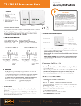
Diagram 3. Cutting current 120A with stand off guide applied
no 0349 302 132
Fig. 9−
−−
−1. Assembly of stand off
guide no 0349 302 131 (50A)
Apply stand off guide on tip of the torch as far
as possible
(to the edge of bevel).
0
0,5
1
1,5
2
2,5
3
0 5 10 15 20 25 30 35 40 45 50
mm
m/min
Fe
Al
Ss
0
0,5
1
1,5
2
2,5
3
3,5
0 5 10 15 20 25 30 35 40
mm
m/min
Fe
Al
Ss
0
1
2
3
4
5
6
0 5 10 15 20 25 30mm
m/min
Fe
Al
Ss
Fig. 9−
−−
−2. Assembly of stand off
guide no 0349 302 132 (100A)

16
Fig. 9-3. LPH 120 Power source – front view
Item No. Qty. Req.
400-415V
3~ 50/60Hz
Qty. Req.
230V/400-415V/440V
3~ 50/60Hz
Part No. Description Circuit symbol
1
2
2
3
4
5
6
7
8
9
10
11
12
13
14
15
1
1
-
3
1
1
1
1
1
1
1
1
1
1
1
2
1
-
1
3
1
1
1
1
1
1
1
1
1
1
1
2
0457 291 001
0457 291 002
0349 302 057
0457 290 003
0457 290 004
0457 290 005
0457 290 006
0457 290 007
0457 290 008
0457 290 009
0457 290 010
0457 290 011
0457 290 012
0457 291 018
0558 000 724
0457 290 015
Front cover
Rotary cam – switch
Rotary cam – switch
LED – holder ( socket )
LED ( green )
LED ( red )
LED ( yellow )
Push – button switch
Push – button cap ( detachable )
Pressure regulator
Pressure gauge
Current connector – socket
Rubber grommet ( with support sleeve )
Current wire with clamp
Plasma cutting torch PT 25
Side panel
W1
W1
D1
D3
D2
W2
“ + ”

17
Fig. 9-4. LPH 120 Power source – left side view
Item No. Qty. Req.
400-415V
3~ 50/60Hz
Qty. Req.
230V/400-415V/440V
3~ 50/60Hz
Part No. Description Circuit symbol
30 1 - 0457 291 003 Transformer TR1
30 - 1 0349 302 058 Transformer TR1
31 1 1 0457 291 004 Resistor set R3
32 3 3 0457 290 018
Resistor (1,65 Ω)
33 1 1 0457 290 019 Contactor 220V ST2
34 1 1 0457 290 020 Ignition block 24V HF
35 1 1 0457 290 021 Choke L1
36 1 - 0457 290 083 Circuit breaker Q
36 - 1 0349 302 055 Circuit breaker Q
39 1 1 0457 290 025 Choke L2
40 2 2 0457 290 026
Swivel wheel ( with brake ) ass′ y
41 1 1 0457 290 027 Base frame
42 2 2 0457 290 028
Fixed wheel ass′y
43 1 1 0457 291 005 Pipe coupler ( straight )
44 1 1 0457 291 006 Coupler
45 1 1 0457 290 030 Pressure switch CZ1
46 1 1 0457 291 007 Electromagnetic valve EZ1
47 4 4 0457 290 032 Stub pipe
48 0457 290 033
Reinforced PVC hose φ5×1,5
49 10 10 0457 290 034 Hose clip
50 1 1 0558 000 756 Receptacle 5 Pole G1
51 1 1 0457 291 008 Stub pipe
52 1 1 0457 291 009 Insulating sleeve
53 1 1 0457 291 010 Special nut
54 1 1 0457 291 011 Stub pipe
55 1 1 0457 291 012 Insulating sleeve
56 1 1 0457 290 037 Special nut
57 1 1 0457 290 041 Console
58 1 1 0457 290 042 Temperature switch WT1
59 2 2 0457 290 031 Electromagnetic valve EZ2, EZ3
60 1 1 0457 291 020 Stub pipe
61 1 1 0457 291 021 Coupler

18
Fig. 9-5. LPH 120 Power source – right side view
Item No. Qty. Req.
400-415V
3~ 50/60Hz
Qty. Req.
230V/400-415V/440V
3~ 50/60Hz
Part No. Description Circuit symbol
90 1 - 0457 290 043 Transformer TR2
90 - 1 0349 302 059 Transformer TR2
91 1 1 0457 291 013 Current sensor ass’y ZS1
92 1 1 0457 290 045 Electronic PCB PL50
93 1 1 0457 290 046 Rectifier bridge PR2
94 2 2 0457 290 047 Fuse holder
95 2 2 0457 290 048 Fuse 1,6A F1, F2
96 1 - 0457 291 014 Contactor ST1
96 - 1 0349 302 061 Contactor ST1
97 1 1 0457 290 050 Capacitor C6
98 1 1 0457 290 051 Clamping ring
99 1 1 0457 290 052 Grip handle
100 1 1 0457 290 053 Roof
101 1 1
0457 290 054 Rectifier block ass′y
PR1
102 1 1
0457 290 055 Capacitor 5µF 450/500V
C4
103 1 1
0457 290 056 Resistor 330kΩ 0,25W
R2
104 1 1
0457 290 057 Resistor 22Ω 2W
R1
105 1 1 0457 290 058 Lug
106 1 1 0457 290 059 Supporting shelf for rectifier bridge
107 3 3
0457 290 060 Capacitor 30µF 450/500V
C1,C2,C3
108 1 1
0457 290 061 Bracket ( capacitors ass′y )
109 1 1 0457 290 062 Fan guard
110 1 1 0457 290 063 Fan 220V 50Hz 0,145kW 1320obr./min M1
111 1 1
0457 290 064 Capacitor 5µF 400V
C5
112 1 1 0457 290 065 Terminal block ( 3-way ) LZ1
113 1 1 0558 001 457 Pressure sensor ( switch ) CZ2
114 1 1 0457 291 016 Pipe coupler
115 1 1 0457 290 066 Varistor V1
116 1 1 0457 290 067 Connector X2
117 1 1 0457 290 068 Connector X3
118 1 1 0457 290 069 Connector X1
119 1 1 0457 290 082 Reed – relay contact ZZ
120 - 1 0349 302 062 Auxiliary contact ST1

19
Fig. 9-6. LPH 120 Power source – rear view
Item No. Qty. Req.
400-415V
3~ 50/60Hz
Qty. Req.
230V/400-415V/440V
3~ 50/60Hz
Part No. Description Circuit symbol
180 1 1 0457 291 017 Rear shield
181 1 1 0457 290 071 Quick detachable coupling
182 1 1 0457 290 072 Hose clip
183 1 1 0457 290 073 Pipe stub
184 1 1 0457 289 029 Filter - regulator
185 1 1 0457 290 075 Pipe coupler ( elbow )
186 1 1 0457 290 076 Pipe coupler ( straight )
187 1 1 0457 290 077 Pneumatic hose PVC 8x1,25
188 1 1 0457 291 019 Supply cable
189 1 - 0457 290 079 Metal cable gland
189 - 1 0349 302 060 Metal cable gland
190 1 1 0457 290 080 Locknut
191 1 1 0457 290 081
Filter cartridge 5µm
5 ORDERING OF SPARE PARTS
1. When ordering spare parts please specify machine model, serial number, designation and parts
order numbers as shown in spare parts list. This simplifies dispatch and ensures correct delivery

ESAB AB
SE--695 81 LAXÅ
SWEDEN
Phone +46 584 81 000
Fax +46 584 123 08
www.esab.com
020314
ESAB subsidiaries and representative offices
Europe
AUSTRIA
ESAB Ges.m.b.H
Vienna--Liesing
Tel: +43 1 888 25 11
Fax: +43 1 888 25 11 85
BELGIUM
S.A. ESAB N.V.
Brussels
Tel: +32 2 745 11 00
Fax: +32 2 726 80 05
THE CZECH REPUBLIC
ESAB VAMBERK s.r.o.
Prague
Tel: +420 2 819 40 885
Fax: +420 2 819 40 120
DENMARK
Aktieselskabet ESAB
Copenhagen-- Valby
Tel:+4536300111
Fax:+4536304003
FINLAND
ESAB Oy
Helsinki
Tel: +358 9 547 761
Fax: +358 9 547 77 71
FRANCE
ESAB France S.A.
Cergy Pontoise
Tel:+33130755500
Fax:+33130755524
GERMANY
ESAB GmbH
Solingen
Tel: +49 212 298 0
Fax: +49 212 298 204
GREAT BRITAIN
ESAB Group (UK) Ltd
Waltham Cross
Tel: +44 1992 76 85 15
Fax: +44 1992 71 58 03
ESAB Automation Ltd
Andover
Tel: +44 1264 33 22 33
Fax: +44 1264 33 20 74
HUNGARY
ESAB Kft
Budapest
Tel:+3612044182
Fax:+3612044186
ITALY
ESAB Saldatura S.p.A.
Mesero (Mi)
Tel:+3902979681
Fax:+390297289181
THE NETHERLANDS
ESAB Nederland B.V.
Utrecht
Tel: +31 30 248 59 22
Fax: +31 30 248 52 60
NORWAY
AS ESAB
Larvik
Tel:+4733121000
Fax:+4733115203
POLAND
ESAB Sp.z.o.o
Warszaw
Tel: +48 22 813 99 63
Fax: +48 22 813 98 81
PORTUGAL
ESAB Lda
Lisbon
Tel: +351 1 837 1527
Fax: +351 1 859 1277
SLOVAKIA
ESAB Slovakia s.r.o.
Bratislava
Tel:+421744882426
Fax:+421744888741
SPAIN
ESAB Ibérica S.A.
Alcobendas (Madrid)
Tel: +34 91 623 11 00
Fax: +34 91 661 51 83
SWEDEN
ESAB Sverige AB
Gothenburg
Tel:+4631509500
Fax:+4631509222
ESAB International AB
Gothenburg
Tel:+4631509000
Fax:+4631509360
SWITZERLAND
ESAB AG
Dietikon
Tel: +41 1 741 25 25
Fax: +41 1 740 30 55
North and South America
ARGENTINA
CONARCO
Buenos Aires
Tel: +54 11 4 753 4039
Fax: +54 11 4 753 6313
BRAZIL
ESAB S.A.
Contagem-- MG
Tel: +55 31 333 43 33
Fax: +55 31 361 31 51
CANADA
ESAB Group Canada Inc.
Missisauga, Ontario
Tel: +1 905 670 02 20
Fax: +1 905 670 48 79
MEXICO
ESAB Mexico S.A.
Monterrey
Tel: +52 8 350 5959
Fax: +52 8 350 7554
USA
ESAB Welding & Cutting Products
Florence, SC
Tel: +1 843 669 44 11
Fax: +1 843 664 44 58
Asia/Pacific
AUSTRALIA
ESAB Australia Pty Ltd
Ermington
Tel: +61 2 9647 1232
Fax: +61 2 9748 1685
CHINA
Shanghai ESAB A/P
Shanghai
Tel: +86 21 6539 7124
Fax: +86 21 6543 6622
INDIA
ESAB India Ltd
Calcutta
Tel: +91 33 478 45 17
Fax: +91 33 468 18 80
INDONESIA
P.T. Esabindo Pratama
Jakarta
Tel: +62 21 460 01 88
Fax: +62 21 461 29 29
MALAYSIA
ESAB (Malaysia) Snd Bhd
Selangor
Tel: +60 3 703 36 15
Fax: +60 3 703 35 52
SINGAPORE
ESAB Singapore Pte Ltd
Singapore
Tel: +65 861 43 22
Fax: +65 861 31 95
ESAB Asia/Pacific Pte Ltd
Singapore
Tel: +65 861 74 42
Fax: +65 863 08 39
SOUTH KOREA
ESAB SeAH Corporation
Kyung --Nam
Tel: +82 551 289 81 11
Fax: +82 551 289 88 63
UNITED ARAB EMIRA TES
ESAB Middle East
Dubai
Tel: +971 4 338 88 29
Fax: +971 4 338 87 29
Representative offices
BULGARIA
ESAB Representative Office
Sofia
Tel/Fax: +359 2 974 42 88
EGYPT
ESAB Egypt
Dokki--Cairo
Tel: +20 2 390 96 69
Fax: +20 2 393 32 13
ROMANIA
ESAB Representative Office
Bucharest
Tel/Fax: +40 1 322 36 74
RUSSIA--CIS
ESAB Representative Office
Moscow
Tel: +7 095 937 98 20
Fax: +7 095 937 95 80
ESAB Representative Office
St Petersburg
Tel: +7 812 325 43 62
Fax: +7 812 325 66 85
Distributors
For addresses and phone
numbers to our distributors in
other countries, please visit our
home page
www.esab.com
/